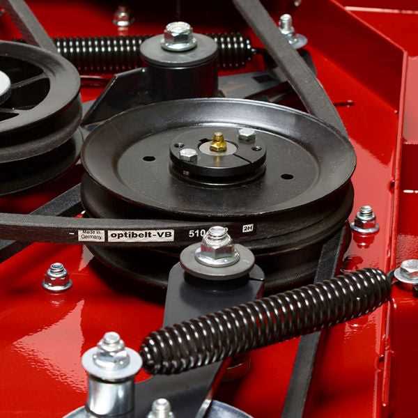
Understanding the structure and arrangement of various elements in machinery is crucial for efficient maintenance and repair. Every mechanical system is made up of interconnected pieces, each serving a specific purpose. Knowing how these pieces fit together can significantly enhance troubleshooting efforts and ensure seamless operation.
This section provides a detailed breakdown of the internal and external elements of essential equipment. By familiarizing yourself with the arrangement and function of individual units, you’ll be better prepared to handle any issues that arise, improving both efficiency and performance.
Whether you’re an expert technician or just beginning to explore mechanical systems, a clear view of how everything works together is invaluable. This guide will offer clarity on each aspect, ensuring a solid grasp of the essential components and their interactions.
Understanding Ferris Mower Parts Diagrams
When maintaining or repairing a riding lawn machine, having a visual breakdown of its components can be extremely useful. These graphical representations help users locate individual items, understand how different elements are assembled, and identify any necessary replacements. Whether it’s for routine upkeep or fixing an issue, knowing how to interpret these illustrations is key to ensuring proper machine functionality.
Why Component Illustrations Matter

Mechanical systems are complex, and visual representations provide a clear guide for understanding how the different mechanisms work together. By studying these, users can familiarize themselves with the layout and placement of items, which can speed up the repair process. These depictions also serve as a reference for identifying specific pieces during ordering or replacement.
Breaking Down the Visual Guide
- Grouping: Items are often grouped by function, making it easier to locate and address issues.
- Labeling: Each element is clearly marked, helping users match the visual reference with real-life components.
- Flow: The flow of the illustration generally follows the assembly process, ensuring clarity in how parts interact.
- Identify the section
How to Read a Ferris Parts Breakdown
Understanding the layout and structure of a component breakdown is crucial for efficient maintenance and repair. These documents provide a detailed view of every individual element within a machine, showing how they fit together and their relationships to one another. Mastering this allows users to identify, order, and replace items quickly, ensuring proper functionality.
The breakdown typically includes a numbered listing, each corresponding to a specific item within the system. Below is an example format you may encounter:
Item Number Description Quantity Part Code 1 Drive Belt 1 12345-AB 2 Blade Assembly 2 Key Components in Ferris Mower Schematics
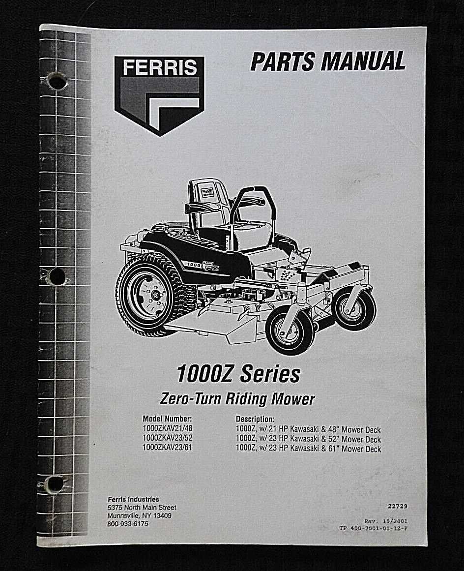
Understanding the layout and primary elements of a lawn mower’s technical blueprint is essential for proper maintenance and repair. These layouts provide detailed visuals, showcasing how individual elements interconnect and contribute to the machine’s overall functionality. Below, we will explore the main components that ensure efficient performance and durability in a typical mower setup.
- Engine Assembly: The heart of the machine, responsible for generating power and driving various systems such as the cutting blades and drive mechanisms.
- Transmission System: Connects the engine to the wheels, allowing controlled movement and speed adjustments across different terrains.
- Cutter Deck: Houses the blades, enabling precision grass trimming through height-adjustable settings.
- Hydraulic Pumps: Facilitate the movement of fluids necessary for steering and blade operation, ensuring smooth handling.
- Control Levers: Provide the operator with the ability to steer, adjust speed, and engage cutting actions with precision.
- Electrical Wiring: Powers essential componen
Exploring Drive System Diagrams for Ferris Mowers
The propulsion mechanism of zero-turn mowers is essential for ensuring smooth and efficient operation across varying terrains. Understanding how the components responsible for movement interact can greatly assist in both maintenance and repairs. This section provides an overview of the key elements that make up the propulsion assembly, highlighting their roles and interactions.
Main Components of the Propulsion Mechanism
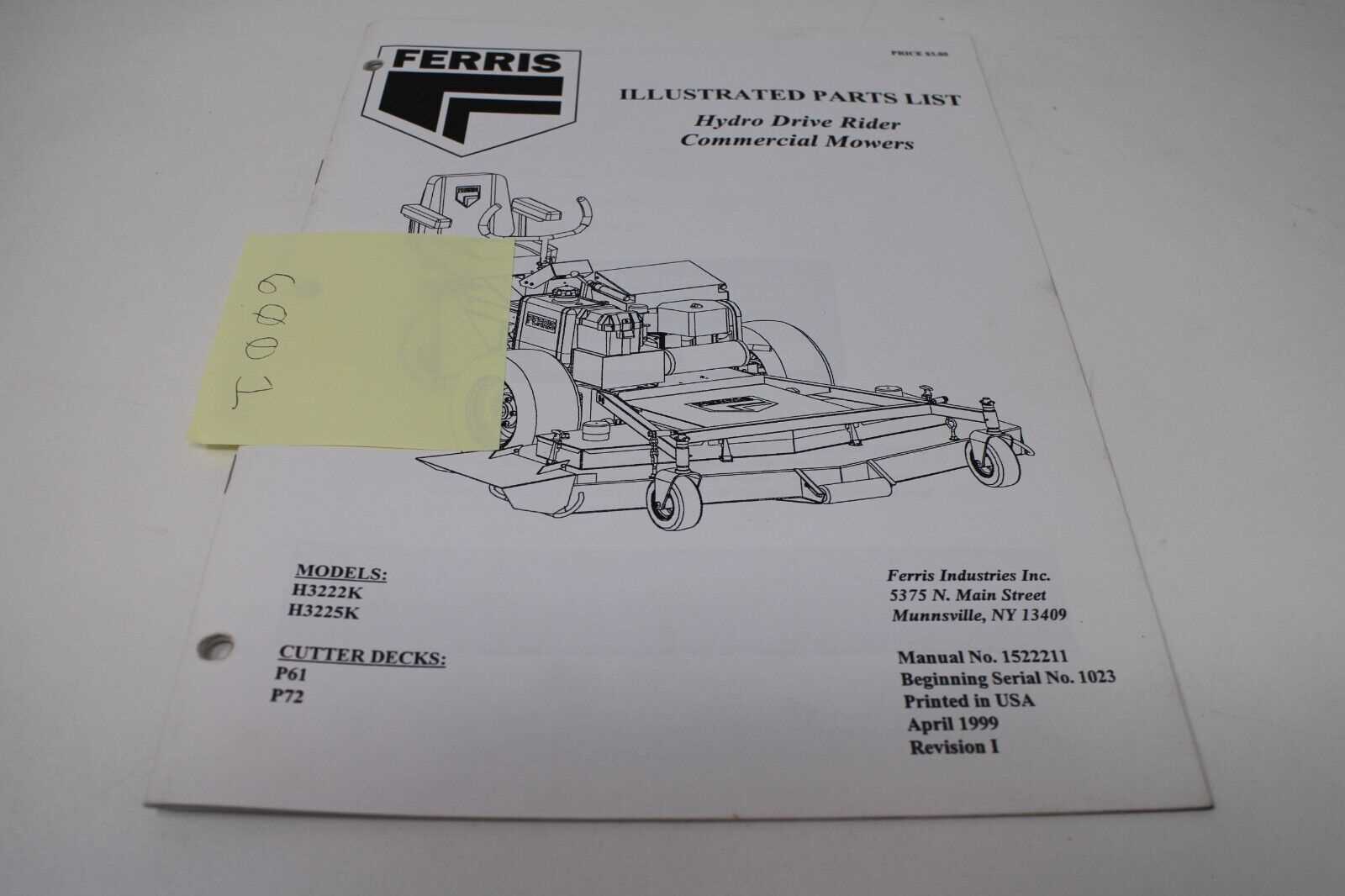
The propulsion mechanism includes various interconnected parts that work together to deliver power from the engine to the wheels. These elements typically involve hydraulic pumps, drive motors, and belt systems. Each of these plays a crucial role in delivering the necessary force to move the machine, enabling it to perform optimally even under tough conditions.
Hydraulic Systems and Their Functionality
One of the core features of the propulsion mechanism is the hydraulic system. This setup uses fluid dynamics to transfer energy, offering a smooth and responsive experience when maneuvering. With a proper understanding of how the hydraulic components function, operators can ensure their machine continues to run efficiently and handle the stresses of frequent use.
Blade Assembly and Deck Parts Identification
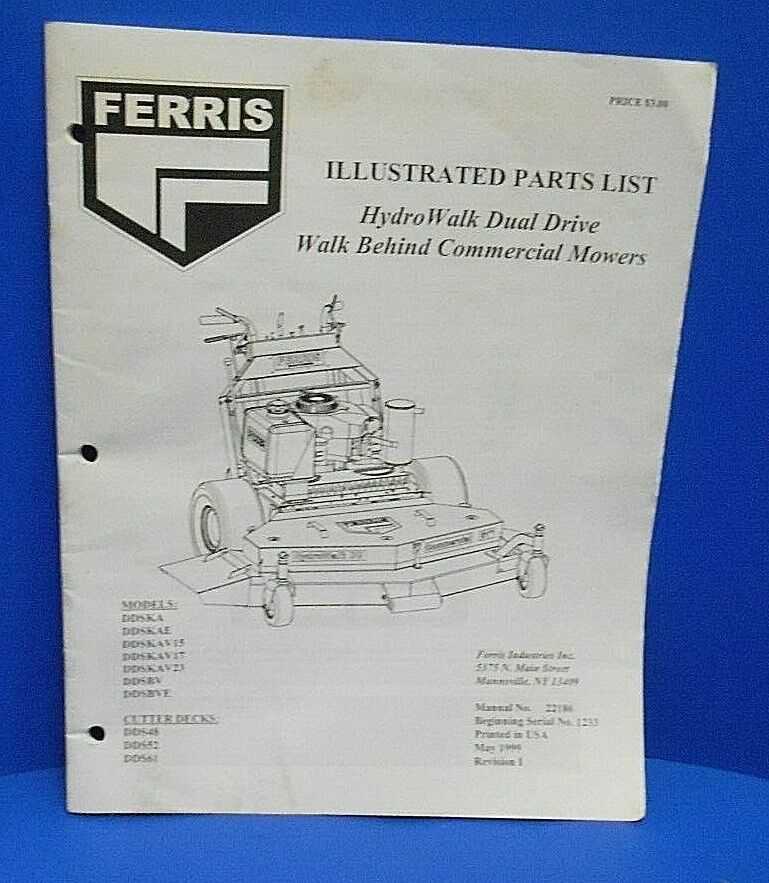
The cutting mechanism and the components beneath the mowing platform play a crucial role in maintaining a smooth and efficient operation. Understanding the arrangement and relationship between these elements is essential for ensuring proper functionality and prolonging the life of the equipment.
Key Components of the Blade System
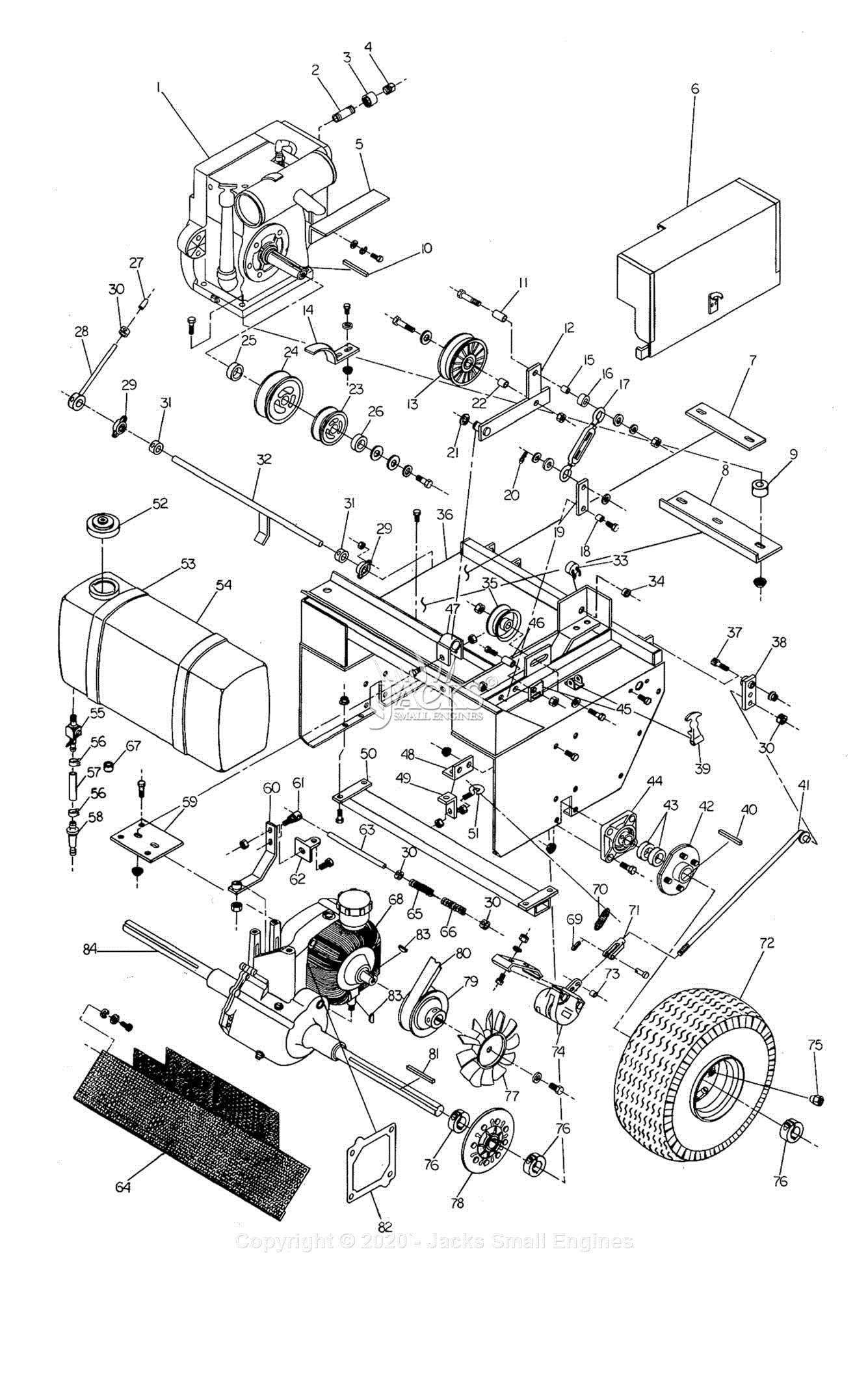
The blade system consists of several essential elements that work together to achieve precise cutting. These include the rotating blades, the mounting hardware, and the support structure that holds everything in place. Identifying these elements helps in performing maintenance and ensuring that the cutting action remains sharp and consistent.
Deck Structure Breakdown
The deck itself serves as the foundation for the blade assembly. It houses multiple parts that contribute to the stability and operation of the mowing process. From the belts that drive the blades to the spindles that ensure smooth rotation, each element within the deck must be inspected regularly to avoid unnecessary wear and ensure optimal performance.
Electrical System Overview in Ferris Diagrams
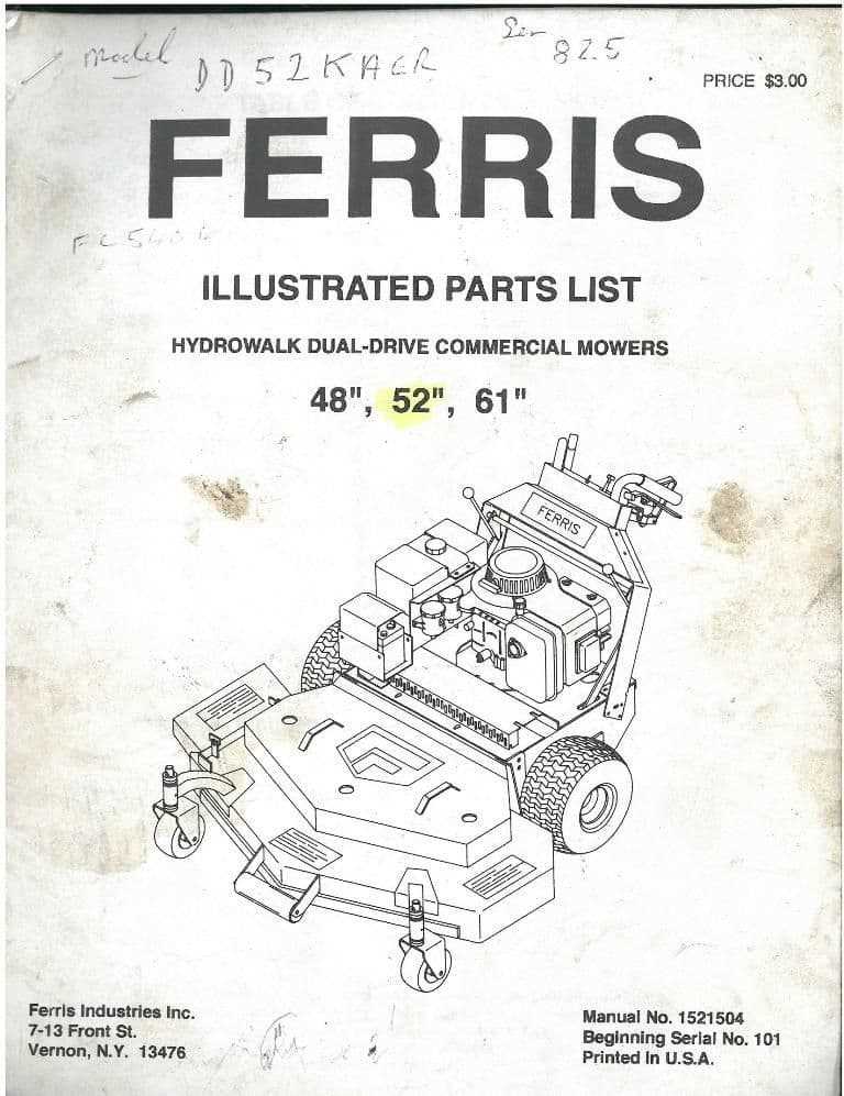
The electrical setup in outdoor machinery plays a vital role in ensuring efficient operation and functionality. Understanding how different components interact within the system is essential for troubleshooting and maintenance. The various circuits, connectors, and control units work together seamlessly to power key functions like ignition, lighting, and control systems, ensuring smooth performance of the equipment.
Typically, these layouts offer a visual guide to the connections between the battery, switches, relays, and sensors. It is important to identify how electrical flows through these elements, as this determines how the machine responds to operator inputs. Moreover, understanding the placement and function of fuses, diodes, and wiring harnesses provides insight into protecting the system from potential damage due to overloads or short circuits.
In-depth knowledge of the electrical architecture can also help diagnose issues such as starting problems, malfunctioning lights, or faulty sensors. The ability to trace current paths and isolate faults makes maintenance faster and more accurate, preventing unnecessary downtime. These technical blueprints are invaluable tools for anyone looking to optimize the lifespan and reliability of their machinery.
Ferris Mower Belt Configuration Explained
Understanding how belts are arranged and function within a mowing machine is crucial for proper maintenance and smooth operation. These components play a significant role in transferring power from the engine to the cutting blades and other essential mechanisms. Proper alignment and tension are key to ensuring optimal performance and longevity of the equipment.
The correct setup of these components ensures that power is transmitted efficiently, minimizing wear and tear. Misalignment or incorrect routing can lead to mechanical failures, poor cutting performance, or even damage to the belts themselves. It is essential to follow specific instructions regarding the routing and placement of each belt to avoid these issues.
Below is a breakdown of important steps to understand and configure the belts accurately:
- Check the engine’s pulley system and ensure it is clean and free of debris.
- Examine each belt for signs of wear or damage before installation.
- Route the belts through the pulleys according to the design to prevent any interference with other moving parts.
- Ensure proper tension is applied to each belt to avoid excessive slack or tightness, which could cause undue strain.
- Test the machine’s functionality after configuration to confirm that all components are working harmoniously.
Maintaining a proper belt arrangement not only enhances performance but also extends the overall lifespan of the machine. Regular checks and timely adjustments can prevent costly repairs and ensure that the mowing process remains efficient and effective.
Locating Engine Parts in Ferris Diagrams
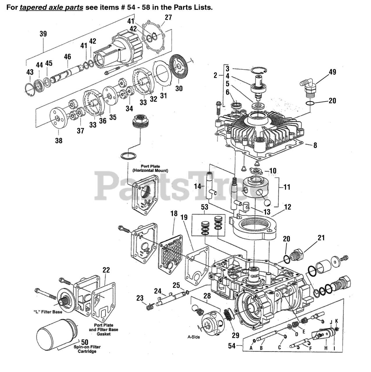
Understanding the layout of engine components can significantly enhance the maintenance and repair process. By analyzing technical schematics, users can identify the precise location of each key element, ensuring accurate diagnostics and efficient problem-solving. These visual representations help break down complex machinery into manageable sections, allowing for a clear view of how the engine is assembled and functions. Knowing where to find specific components is essential for anyone working on engine systems, whether for routine upkeep or major repairs.
One of the first steps in navigating these illustrations is familiarizing oneself with the common symbols and notations used to represent various elements. Each visual guide typically has a legend or key, which makes it easier to interpret the markings. Once the user can quickly identify symbols for the engine’s core systems–such as the fuel, ignition, and cooling systems–it becomes much easier to locate any given part. This organized approach is crucial in preventing confusion and ensuring that no element is overlooked.
By methodically following the flow of the diagram, users can trace the connections between different components. This is particularly useful when dealing with complex systems where multiple parts interact. Identifying the location of key pieces, such as pistons, valves, or camshafts, becomes straightforward, especially when focusing on specific sections of the schematic. Mastering the ability to efficiently locate these components will ultimately lead to quicker and more accurate servicing of the engine.
Common Symbols in Ferris Parts Layouts
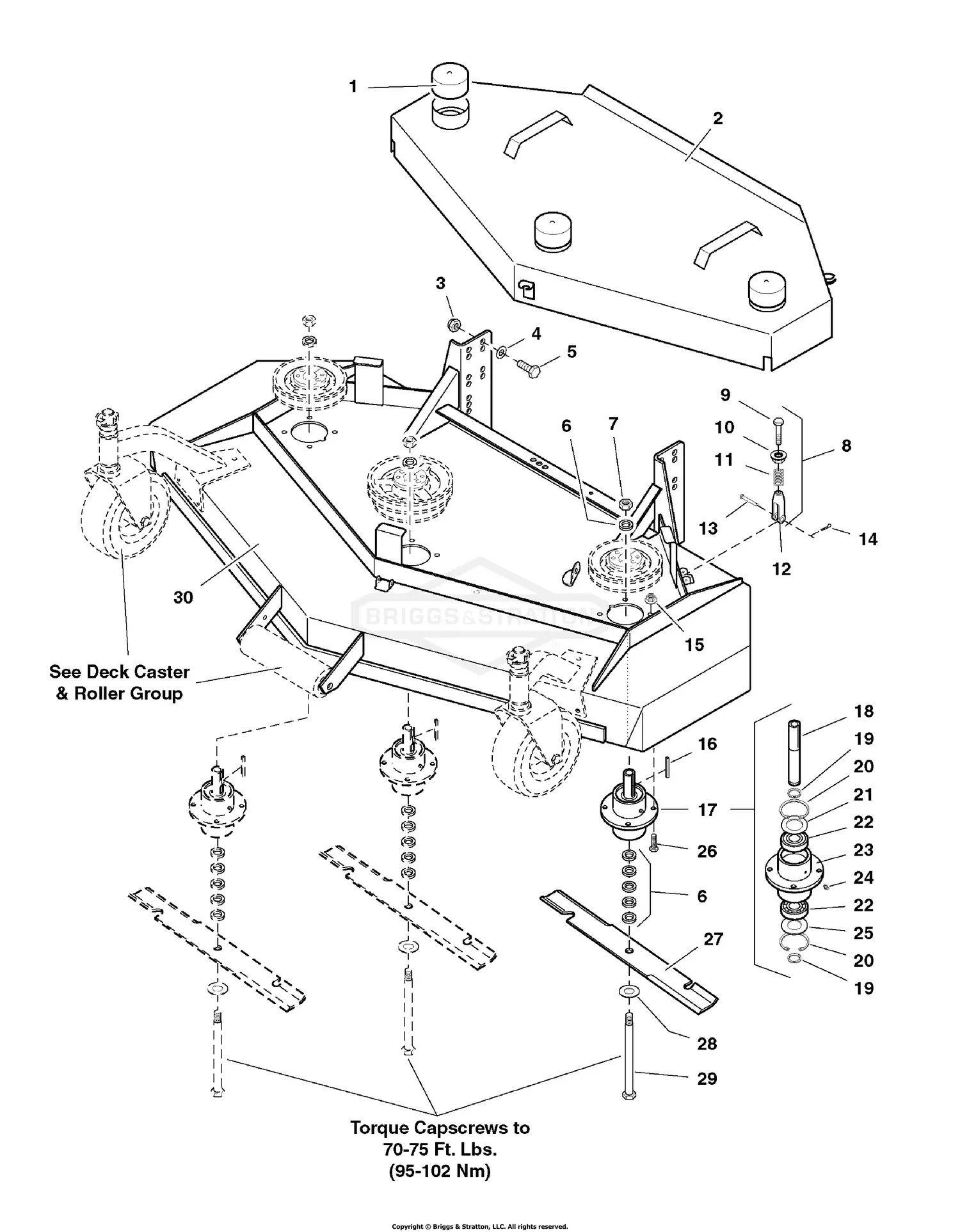
When working with technical illustrations of machinery, it’s essential to understand the symbols used to represent various components and systems. These graphical representations serve as a universal language, allowing users to quickly identify individual parts and understand their functions within a larger mechanism. By recognizing and interpreting these symbols, technicians and engineers can easily follow assembly, disassembly, and maintenance procedures.
Arrows are among the most common symbols used, typically indicating direction or flow, such as the path of fluid, air, or electrical current. These arrows help convey how certain elements interact with each other, ensuring that users know how components fit together or move in relation to one another.
Circles often symbolize rotational parts like gears, pulleys, or bearings. Their placement within a layout can signify the position or orientation of these rotating elements within a system.
Squares and rectangles are frequently used to represent fixed, stationary elements such as frames, housings, or any component that serves as the base or structure of the assembly. These shapes give a clear visual indication of the parts that remain immobile during operation.
Lines, both solid and dashed, serve various functions. Solid lines usually depict the main body of a system, while dashed lines represent auxiliary connections or secondary paths, such as wiring or tubing routes that may not be immediately visible but are crucial for proper functionality.
In addition, letter codes and number labels are often included in these visual layouts to provide further clarity. These alphanumeric designations correspond to specific parts, allowing users to reference manuals or spare parts lists more easily when making repairs or upgrades.
Understanding Ferris Mower Suspension Components
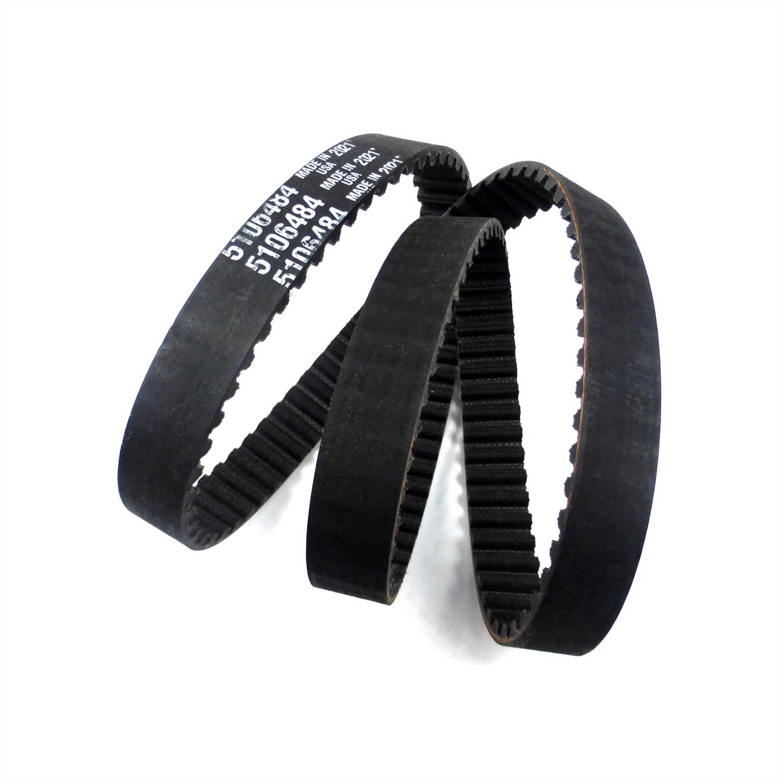
The suspension system of a lawn care machine plays a crucial role in enhancing comfort and improving overall performance. It is designed to absorb shocks, allowing for smoother operation over uneven terrain. This system helps maintain the integrity of the machine while ensuring that the operator experiences less fatigue, even when navigating rough surfaces.
Key elements of this system include shock absorbers, springs, and linkages. These components work together to manage the impact forces experienced during operation, reducing wear and tear on the vehicle and improving user experience. The right configuration of these elements ensures that the mower remains stable and responsive, even under challenging conditions.
Each of these elements contributes to the overall performance and durability of the machine. Understanding how they interact can help users maintain their equipment more effectively, ensuring optimal functionality for years to come.
Hydraulic System Parts Diagram for Ferris Mowers
The hydraulic system plays a crucial role in the performance and efficiency of lawn care machinery. Understanding the components that make up this essential system can significantly aid in maintenance, troubleshooting, and ensuring optimal operation. This section covers the key elements of the hydraulic system used in these machines, providing a visual guide to their interconnection and functions.
Key Components of the Hydraulic Mechanism
The core of the hydraulic system is the pump, which generates the pressure needed to move fluid through the system. Coupled with the pump are various valves that control fluid flow and direction. These valves can be manually or electronically controlled to regulate the speed and direction of hydraulic actuators, such as cylinders and motors. Each part works in unison to provide smooth, powerful movement to critical components like the mower blades and wheel drives.
Fluid Flow and Connection Points
At the heart of the system are the hoses and fittings that connect the various components. These elements are essential for maintaining fluid pressure and preventing leaks. Regular inspection and replacement of hoses and fittings ensure that the hydraulic fluid circulates effectively without any disruptions. Proper maintenance of these connections is vital for avoiding system failures and keeping the machinery in top working condition.
How to Use Ferris Parts Diagrams for Repairs
Understanding how to access and utilize visual schematics for mechanical components can significantly streamline the repair process. These detailed illustrations offer a clear view of how various pieces fit together, helping you identify any faulty elements. When tackling maintenance or replacements, having a reference that shows the exact layout and connection points of each part is essential for accuracy and efficiency.
Step 1: Begin by locating the specific illustration that corresponds to your machine model. Each visual guide is tailored to a particular model, so it’s crucial to ensure you are using the correct one. This will help prevent confusion and save time by providing precise information relevant to the issue at hand.
Step 2: Study the diagram carefully, paying attention to each component and its role in the overall system. Identify the part that needs repair or replacement. Using these visuals, you can match the part number with the corresponding physical element on your equipment, making the process of locating and removing it straightforward.
Step 3: Follow the assembly or disassembly instructions step by step. These guides often include useful tips on how to handle and manipulate each component, ensuring that you avoid mistakes or damage during the process. For complex repairs, the visual aid ensures that all parts are correctly reassembled, preventing potential malfunctions.
By referring to these comprehensive visual guides, you ensure a higher level of precision in repairs, leading to faster completion and fewer errors.