Understanding the inner workings of complex machinery is essential for anyone involved in maintenance, repair, or engineering. Detailed visual aids offer an in-depth view into the intricate systems that keep these machines running efficiently. These resources are designed to provide clarity, making it easier to identify individual elements within a system.
Whether you’re troubleshooting an issue or performing routine upkeep, having access to organized and detailed illustrations is invaluable. With clear and structured representations, pinpointing a specific component or connection becomes a straightforward task, helping to streamline any technical work.
Visual guides are especially useful when it comes to tackling issues quickly and accurately. Not only do they highlight every necessary element, but they also present an overall structure, allowing technicians to confidently address any problem.
Understanding Cat Parts Diagrams
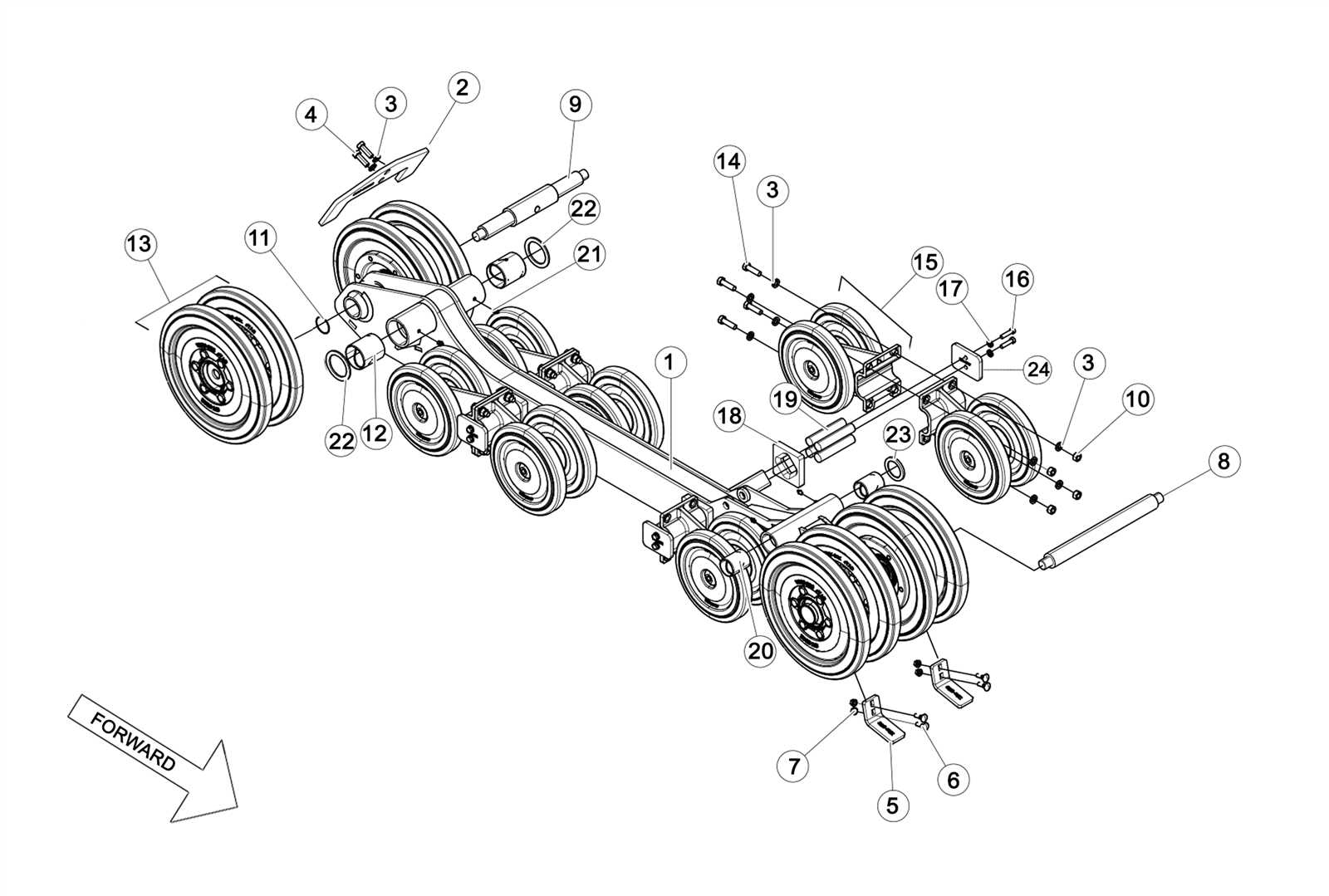
Exploring visual schematics is key to grasping the structure and functionality of various components within a machine. These graphical representations provide an overview of how individual elements connect and work together, making it easier to identify, repair, or replace necessary pieces. Proper interpretation of such illustrations ensures efficient maintenance and troubleshooting.
Breaking Down the Structure
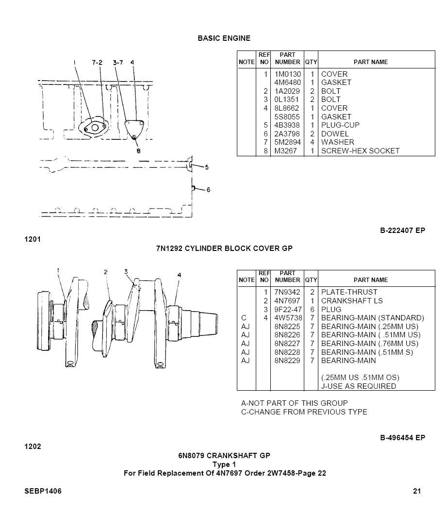
Each illustration is typically organized into sections, allowing users to focus on specific areas. Understanding the layout and arrangement of the pieces helps streamline repair processes and ensures accurate handling of each task. It’s important to pay attention to the labeling and numbering within the visual guide.
Using Visual Guides for Maintenance
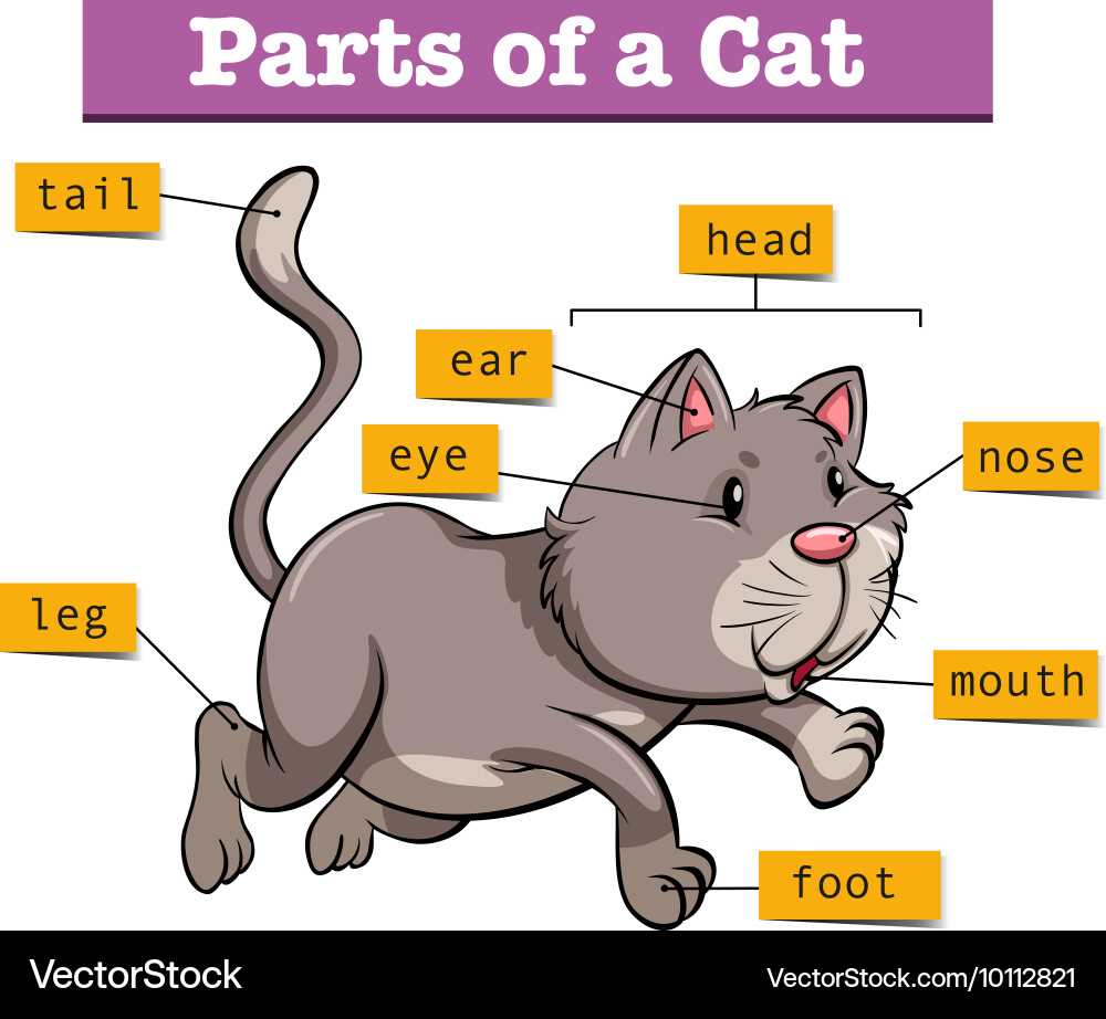
These illustrations are invaluable for both professionals and novices in performing routine inspections or addressing malfunctions. By clearly displaying the positioning of different elements, these guides help ensure that any work performed aligns with the machine’s original design, reducing the likelihood of errors.
How to Read Component Schematics
Understanding component schematics is essential for anyone working with technical systems. These graphical representations allow you to grasp how various elements interact within a system and help troubleshoot issues effectively. By familiarizing yourself with common symbols and reading conventions, you can quickly interpret the structure and function of each part within a larger setup.
Basic Symbols and Their Meaning
Each component in a schematic is represented by a unique symbol. For instance, resistors, capacitors, and transistors all have standardized icons. Learning these symbols is the first step in decoding the diagram. Along with the icons, connections between elements are marked with lines that indicate electrical or mechanical links.
Following the Flow of Information

Schematics are typically laid out to show the logical flow of energy or signals. This means that reading from left to right or top to bottom often helps trace how different sections interact. Understanding this flow will aid you in diagnosing faults and identifying key areas for maintenance or upgrades.
Finding the Right Replacement Parts
Locating suitable components for machinery can often be a challenging task. Whether it’s ensuring compatibility or understanding the specific needs of your equipment, having a reliable method to identify the correct pieces is essential. It’s not just about fitting the item into place; it’s about ensuring performance and durability over time.
Understanding Equipment Requirements
Before selecting any replacement, it’s crucial to understand the specific needs of the machinery. Different models may have unique requirements based on their function and age. Researching the technical specifications and ensuring the chosen components align with these factors will prevent future issues.
Comparing Alternatives
There are often multiple options available when searching for replacements. To make an informed decision, consider factors such as material quality, price, and manufacturer reputation. Comparing these aspects side by side can help make the right choice.
| Feature | Option 1 | Option 2 |
|---|
| Component | Description |
|---|---|
| Compressor | Compresses refrigerant and circulates it through the system. |
| Condenser | Releases heat from the refrigerant to the outside environment. |
| Evaporator | Absorbs heat from the environment, cooling the interior space. |
| Expansion Valve | Regulates the flow of refrigerant, allowing for pressure reduction. |
System Functionality and Flow
Understanding how these components interact is critical for diagnosing issues and optimizing performance. The flow of refrigerant throughout the system illustrates the transition of energy, from heat absorption to heat dissipation. Familiarity with this cycle enables better decision-making when it comes to repairs and enhancements.
Locating Specific Parts in Schematics
Understanding how to find particular components within technical illustrations is essential for effective maintenance and repair. Familiarity with the layout and symbols used can significantly streamline the process, allowing for quicker identification of items that need attention.
Understanding Symbol Representation
Each element in a technical representation is denoted by unique symbols that convey specific information. Recognizing these symbols is crucial, as they serve as a visual guide, facilitating the identification of components and their functions within the overall system.
Navigating Through Complex Layouts
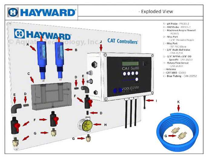
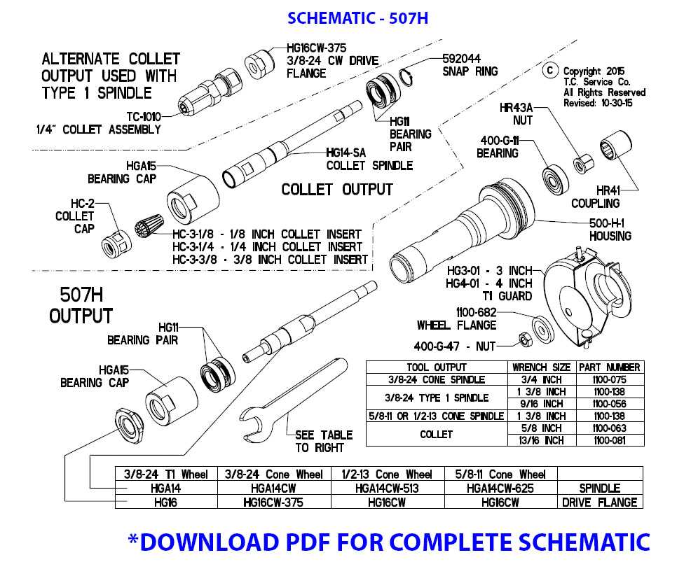
When dealing with intricate layouts, a systematic approach is beneficial. Start by referencing the legend or key that accompanies the illustration. This will provide clarity on the symbols used. Once familiar with the representations, trace the lines connecting components to better understand their relationships and locate the desired item swiftly.
Maintenance Tips Using Diagrams
Effective upkeep of machinery can greatly benefit from visual representations. Utilizing these visuals enhances comprehension, ensuring that every component is appropriately addressed during maintenance sessions. They serve as an invaluable resource for identifying parts and understanding their relationships within the entire system.
When conducting maintenance, it’s crucial to refer to these visuals regularly. They can assist in pinpointing specific areas that require attention, streamlining the repair process. Before starting any task, ensure that you have a clear understanding of the layout presented in the illustrations. This knowledge will help you avoid unnecessary errors and promote efficiency.
Additionally, make it a habit to annotate these visuals during your work. By marking areas that have been inspected or parts that need replacement, you create a personalized reference for future maintenance tasks. This practice not only saves time but also fosters a deeper understanding of the overall structure, ultimately leading to better performance and longevity of the equipment.
Comparing Diagrams for Different Models
Analyzing visual representations of components across various models reveals significant insights into their design and functionality. Understanding these illustrations is crucial for effective maintenance and repair, as each model may showcase unique features and specifications.
When examining these representations, it is essential to consider several factors:
- Design Variations: Different models often exhibit distinct layouts, impacting accessibility and ease of use.
- Component Functions: Each illustration highlights specific roles of components, which can vary between models.
- Maintenance Requirements: Some designs may necessitate unique servicing approaches, making it vital to identify these differences.
For a more in-depth understanding, one can analyze the following aspects:
- Visual Clarity: Assessing how clearly each representation communicates the arrangement and interconnection of elements.
- Detail Level: Comparing the amount of detail provided can indicate the complexity involved in maintenance tasks.
- Compatibility: Identifying how interchangeable components may be across different models, which can streamline repairs.
By closely examining these aspects, users can better navigate the intricacies of various models, enhancing their operational efficiency.
