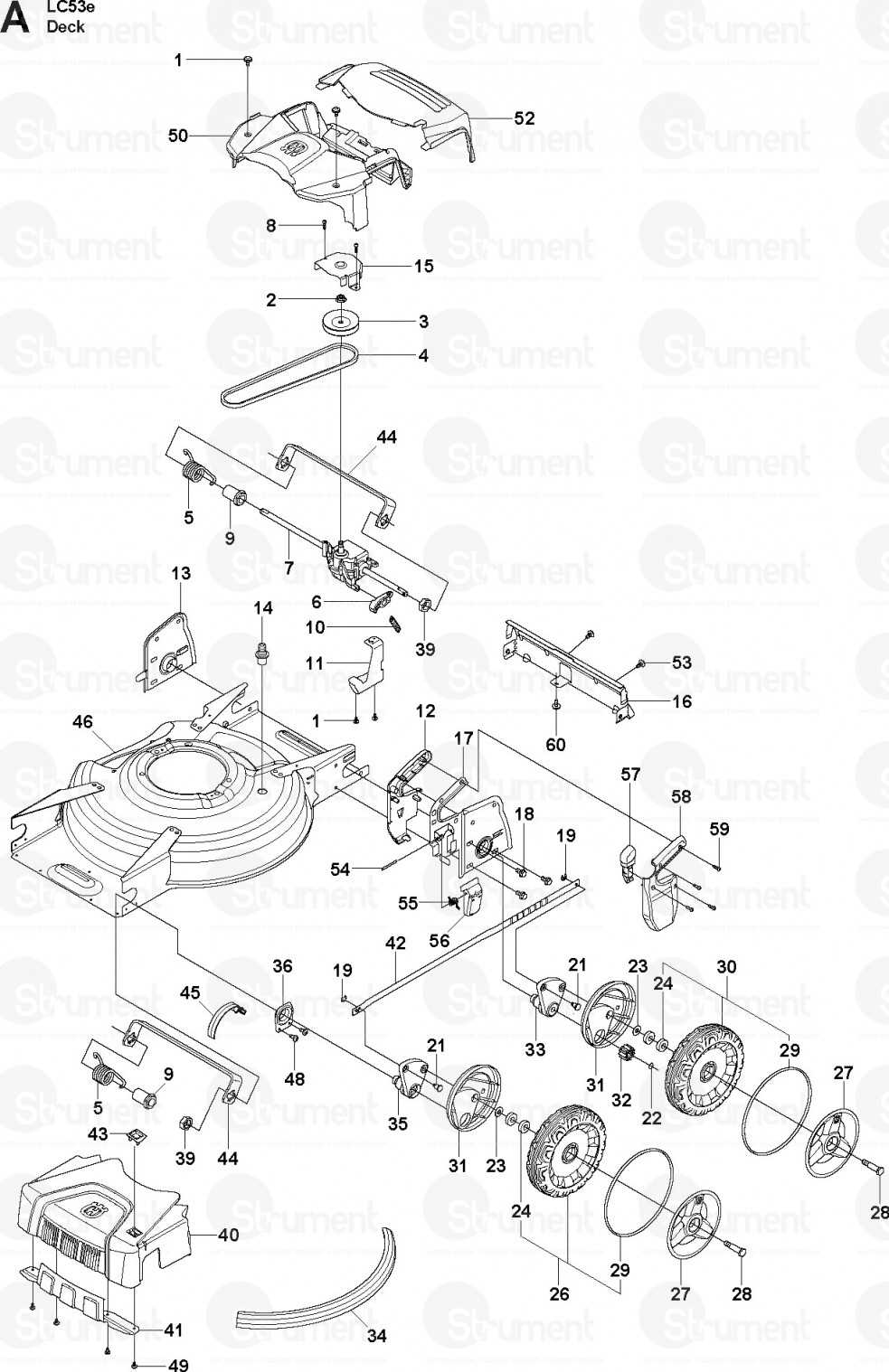
hu800awd parts diagram

When it comes to maintaining outdoor equipment, having a clear understanding of the various elements and their placement can significantly simplify the process. Knowing the layout of individual components helps in identifying potential issues and ensures smoother repairs or replacements. This section aims to offer a comprehensive overview of essential mechanical elements and their arrangement.

Efficient maintenance often relies on recognizing how different elements are interconnected. Properly understanding the structure can make troubleshooting more intuitive and enable quicker identification of necessary replacements. With an organized layout, pinpointing specific areas for repair becomes less challenging.

Recognizing each mechanical element in relation to others not only aids in troubleshooting but also helps in preventative care. Ensuring that all components function together harmoniously extends the life of the equipment and reduces downtime.

Main Features of the HU800AWD

hu800awd parts diagram

This section outlines the key characteristics that make this lawn maintenance tool a practical choice for users seeking efficiency and convenience. The machine is designed to handle various terrains and offer ease of use while performing its primary tasks. Below, we explore the main elements that contribute to its functionality and overall performance.

Engine Power and Efficiency
hu800awd parts diagram

Equipped with a robust motor, this equipment provides ample force for tackling different grass lengths and thicknesses. The engine’s design ensures consistent performance, making it suitable for extended use. Additionally, its fuel consumption is optimized, helping users minimize refueling frequency during operation.

Adjustability and Comfort
hu800awd parts diagram

The device features multiple settings that allow users to customize its operation to suit specific lawn conditions. The handle height can be adjusted, ensuring ergonomic use for individuals of different statures. The cutting height is also flexible, enabling smooth adaptation to various lawn preferences.

Exploring the Cutting Mechanism

The cutting mechanism plays a crucial role in achieving a clean and efficient trim on various terrains. Understanding how this system operates helps in maintaining optimal performance and ensures a more precise cut.

The core of the cutting function relies on a rotating blade system, which slices through vegetation with high speed and accuracy. The balance and sharpness of the blades significantly influence the quality of the trimming, making regular inspections essential for sustained efficiency.

Blade adjustments and proper alignment are key to adapting to different grass types and heights. By fine-tuning these elements, users can enhance the overall performance, leading to smoother operation and more consistent results.

In addition to blade maintenance, cleaning the housing around the cutting area can prevent blockages and reduce wear over time. Keeping the mechanism free of debris not only extends its lifespan but also ensures safety during use.

Drive System Overview

The drive system plays a crucial role in ensuring smooth movement and optimal functionality of the machine. It is designed to transmit power efficiently, allowing the equipment to maintain a consistent speed and handle various terrains with ease. This section provides an outline of the key components involved in the system and their interactions to achieve reliable performance.

Primary Components of the Drive System

The drive system consists of multiple interconnected elements that work together to convert engine power into forward motion. Key parts include the transmission, which manages speed variations, and the drive belt, which transfers energy from the engine to the wheels. Each component is essential for maintaining proper operation and ensuring the equipment responds effectively to user commands.

Role of the Transmission and Belts

The transmission acts as the control center, allowing for adjustments in speed and torque to adapt to different surfaces. The drive belts play a supporting role, ensuring the continuous transfer of motion between the engine and the wheels. Regular inspection and upkeep of these components are critical for prolonging the system’s lifespan and avoiding potential issues.

Proper Maintenance Practices are vital to keeping

Engine Parts Breakdown

The internal combustion engine consists of numerous components that work together to ensure optimal performance. Understanding the structure of these elements is crucial for maintaining the equipment and diagnosing potential issues. Below is an overview of the key elements that compose the engine, along with their primary functions and interconnections.

  • Cylinder: The core chamber where fuel combustion occurs, driving the piston’s movement and generating power.
  • Piston: Moves up and down within the cylinder, converting the force of combustion into mechanical energy.
  • Crankshaft: Transforms the linear motion of the piston into rotational motion, enabling the operation of various mechanisms.
  • Camshaft: Controls the opening and closing of valves, ensuring proper timing for the intake of air and expulsion of exhaust gases.
  • Valves: Regulate the flow of air and exhaust within the engine, playing a critical role in the combustion cycle.
  • Connecting Rod: Links the piston to the crankshaft, transferring the piston’s motion to the crankshaft.
  • Flywheel: Helps maintain a smooth rotation by storing rotational energy, reducing vibrations

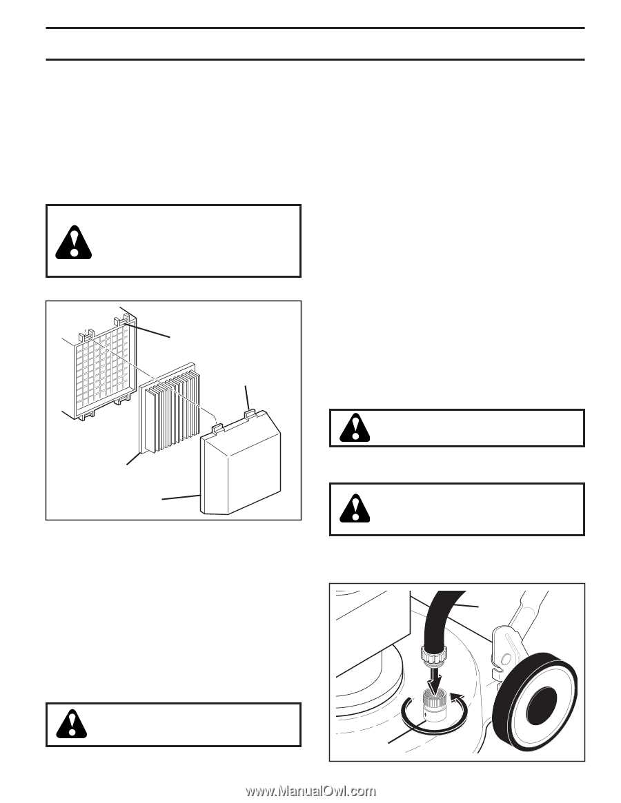
    Replacing the Air Filter

    Keeping the air filter in good condition is essential for ensuring the equipment functions efficiently. Regular replacement helps maintain optimal airflow, preventing dirt and debris from clogging the system. This section provides step-by-step instructions for changing the filter to keep the machine performing at its best.

    1. Begin by turning off the equipment and disconnecting the power source to ensure safety.
    2. Locate the air filter cover, usually found near the engine. Release the cover by removing any fasteners or clips securing it in place.
    3. Carefully take out the old filter, noting its orientation for proper replacement. Check for any accumulated dirt in the compartment and clean it if necessary.
    4. Insert the new filter, ensuring it fits snugly in the designated slot. Make sure it matches the orientation of the previous filter.
    5. Reattach the cover and secure it with the fasteners or clips removed earlier. Double-check that everything is firmly in place.
    6. Reconnect the power source and start the equipment to confirm proper installation an

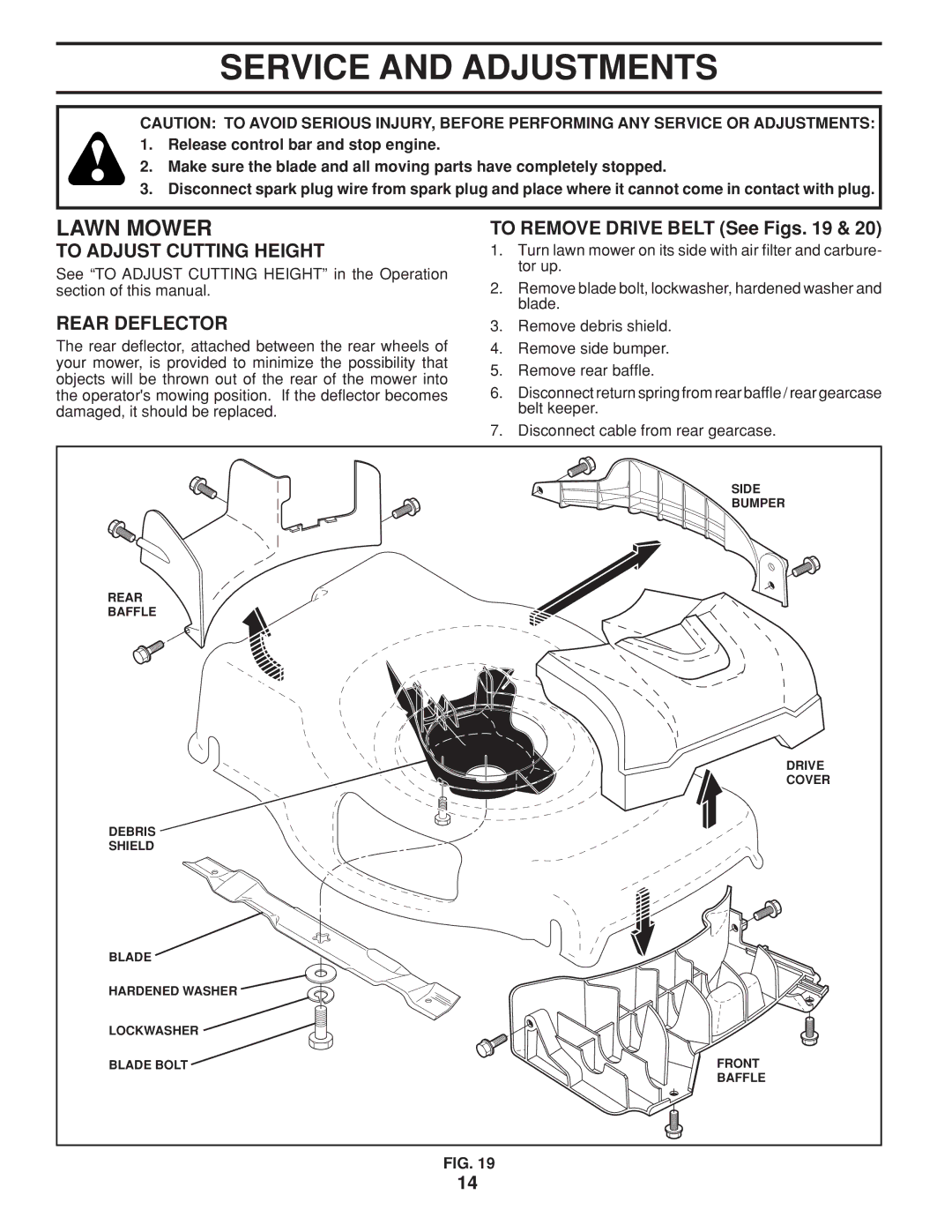
      Blade Assembly Instructions

      Assembling the cutting mechanism of your lawn maintenance equipment is a crucial step to ensure optimal performance. This section provides clear guidelines for putting together the components necessary for effective operation. Follow these instructions carefully to achieve the best results.

      Required Components

      • Cutting blade
      • Mounting hardware
      • Adjustment tools

      Assembly Steps

      1. Begin by securing the machine on a flat surface to ensure stability during assembly.
      2. Locate the cutting blade and inspect it for any damage or wear.
      3. Align the blade with the mounting points on the device, ensuring it fits snugly.
      4. Insert the provided hardware into the mounting holes and tighten them securely using the appropriate tools.
      5. Check the alignment of the blade, adjusting if necessary to ensure it is level.
      6. Once aligned, double-check all fastenings to confirm that everything is securely in place.

      Following these steps will help ensure that your cutting mechanism is assembled correctly and ready for use. Regular maintenance and checks are recommended to keep it in optimal condition.

      Deck and Frame Structure

      The design and construction of the platform and framework play a crucial role in the overall stability and functionality of any machinery. These components serve as the foundation, ensuring that all other elements are securely supported and aligned. The robustness of the structure is vital for maintaining performance under various operating conditions.

      Typically, the framework consists of durable materials that withstand wear and tear while providing the necessary strength. The platform is designed to facilitate easy access for maintenance and operations, often incorporating features that enhance user safety and convenience. Understanding the intricacies of this structure is essential for effective assembly and repair.

      Moreover, attention to detail in the design process can lead to improved efficiency and longevity of the equipment. Each element must be precisely engineered to ensure compatibility and performance, making this aspect of machinery an area of significant importance in engineering practices.

      Wheels and Axle Components

      The wheel and axle assembly is a fundamental aspect of various machinery, playing a crucial role in movement and stability. Understanding the various components involved in this system is essential for ensuring optimal performance and longevity. This section delves into the critical elements that make up these assemblies, highlighting their functions and importance.

      Key Wheel Elements

      hu800awd parts diagram

      Wheels are designed to support the load while enabling smooth movement. Key elements include the tread, which provides traction, and the hub, which serves as the connection point to the axle. The design and material of these components can significantly affect the overall efficiency and durability of the machine.

      Axle Functions

      The axle is the shaft that connects the wheels, allowing them to rotate simultaneously. It plays a vital role in transferring power from the engine to the wheels, facilitating movement. The type of axle, whether rigid or flexible, can influence handling characteristics and overall performance.

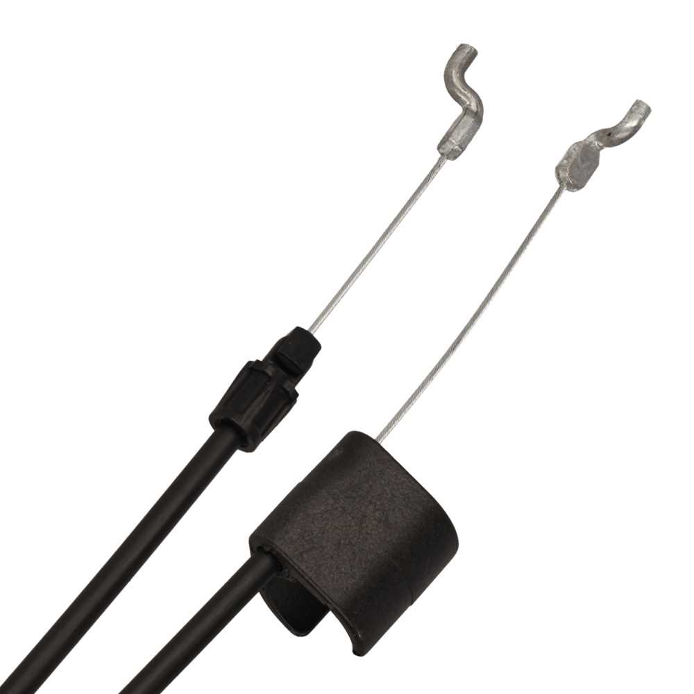
      Handle and Control Setup

      This section focuses on the arrangement and configuration of the device’s gripping mechanisms and operational controls. Ensuring these elements are set up correctly is crucial for optimal performance and user experience. Proper alignment and accessibility can significantly enhance functionality and ease of use.

      Components Overview

      The following table outlines the essential components involved in the handle and control setup, along with their respective functions:

Feature Description
Motor Strength Ensures powerful and consistent performance.
Fuel Efficiency Designed to reduce fuel consumption.
Adjustable Handle
Component Function
Handle Grip Provides a secure hold for maneuverability.
Control Buttons Enable various operational modes and settings.
Trigger Mechanism Activates primary functions of the device.
Adjustment Knob Allows fine-tuning of performance parameters.

Installation Guidelines

To achieve a reliable setup, follow these installation guidelines: ensure the handle is securely attached, check that all controls are easily reachable, and confirm that the components function smoothly together. Regular maintenance and adjustments may be required to uphold performance standards.

Maintenance Tips for Key Parts

Ensuring the longevity and optimal performance of essential components in your equipment requires regular care and attention. By adhering to proper maintenance practices, you can enhance functionality and prevent unnecessary breakdowns. This section provides practical advice for maintaining critical elements to ensure reliable operation.

Regularly inspect the main units for signs of wear or damage. Keeping an eye on potential issues early can save you from costly repairs later. Always follow the manufacturer’s recommendations for maintenance schedules to guarantee that each part functions at its best.

Utilize appropriate cleaning techniques tailored to specific materials and designs. Accumulation of dirt and debris can hinder performance, so gentle cleaning should be part of your routine. For moving parts, lubricating as per guidelines helps minimize friction and ensures smooth operation.

Lastly, replace any worn or damaged components promptly. Ignoring these issues can lead to more severe problems down the line. Staying proactive about replacements can significantly extend the lifespan of your equipment and improve overall efficiency.

Troubleshooting Common Part Issues

Identifying and resolving issues related to components can significantly enhance the performance of your device. Many users encounter common problems that can often be addressed with a systematic approach. Below are typical concerns and their potential solutions.

  • Component Not Functioning:
    • Ensure that the device is properly powered on.
    • Check for loose connections that may disrupt functionality.
    • Inspect the component for visible signs of damage.
  • Unusual Noises:
    • Examine the installation of the part to confirm it is secure.
    • Look for any foreign objects that might be obstructing movement.
    • Lubricate moving parts if necessary to reduce friction.
  • Decreased Performance:
    • Regularly clean the component to remove debris and dust buildup.
    • Check for worn-out pieces that may require replacement.
    • Ensure that all connections are tight and secure to maintain optimal function.
  • Inconsistent Operation:
    • Test the part in different conditions to identify patterns in its behavior.
    • Consult the manual for troubleshooting guidance specific to the component.
    • Consider seeking professional assistance if the problem persists.

By systematically addressing these issues, users can often restore functionality and extend the lifespan of their equipment.