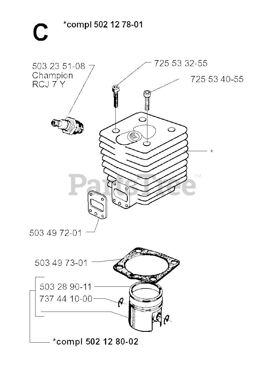
When it comes to maintaining and repairing mechanical devices, having a clear visual guide to their internal structure is essential. A well-organized schematic offers a comprehensive overview of each element, showing how various pieces come together to form a functional system. This kind of clarity is critical for both seasoned professionals and those newer to the world of machinery.
Each element within the machine plays a distinct role in ensuring smooth operation, and knowing the precise layout and interconnection of these elements can simplify troubleshooting and repairs. By understanding the arrangement of crucial components, users can quickly identify which sections need attention, ensuring efficient maintenance practices.
Exploring the layout helps to pinpoint areas where wear and tear are most likely to occur, making it easier to plan for replacements or upgrades. With a detailed guide at hand, anyone can better navigate the intricacies of this equipment, ensuring its longevity and optimal performance.
Jonsered 520sp Parts Overview
The structure of this model’s components is designed to ensure smooth functionality and durability. Each element plays a vital role in maintaining overall performance, making it crucial to understand how they interact. Familiarity with key components enhances maintenance and improves operational efficiency.
Engine components power the machine, while other elements, such as drive systems and cutting mechanisms, work together to provide reliable output. Ensuring each component is in optimal condition is essential for long-lasting performance and safety during use.
Key Components of the 520sp Chainsaw
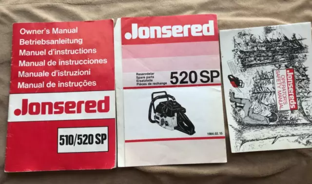
The structure of this chainsaw is made up of several essential elements that work together to ensure its smooth operation. Each part plays a critical role in maintaining efficiency and delivering reliable performance. Understanding the main components can help users keep their equipment in optimal condition and perform necessary maintenance or repairs with confidence.
The engine, which powers the cutting mechanism, is the heart of the tool, providing the energy required for heavy-duty tasks. The cutting chain, tensioned around the guide bar, is responsible for delivering the sharp, precise cuts. The handle system, designed for comfort and stability, allows for controlled and safe usage.
Other crucial elements include the ignition system, which ensures quick start-up, and the fuel and oil tanks, which provide the necessary fluids for long-term operation. Proper maintenance of these key components is essential for extending the lifespan of the equipment and achieving consistent, high-quality results.
Diagram for Engine and Fuel System
Understanding the layout of the engine and fuel system is essential for proper maintenance and repairs. This section provides a detailed overview of how the components interact to ensure smooth operation, focusing on the critical parts responsible for powering and fueling the machine.
| Component | Function |
|---|---|
| Carburetor | Mixes air and fuel to create a combustible mixture for the engine. |
| Fuel Tank | Stores the gasoline needed to power the engine. |
| Ignition System | Generates the spark needed to ignite the air-fuel mixture. |
| Exhaust | Channels the gases produced by combustion away from the engine. |
Understanding the Cutting Chain Assembly
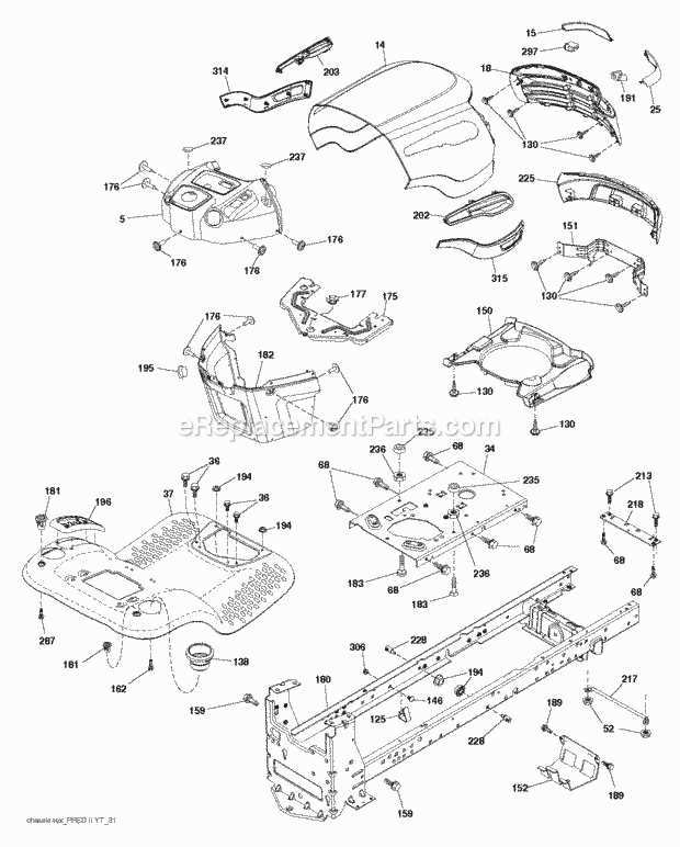
The cutting chain is a vital component in any chainsaw system, designed to ensure efficient performance during operation. Proper assembly and alignment of this element are crucial for maintaining both safety and functionality. Understanding how its various segments interact with each other can help in troubleshooting and regular maintenance.
| Component | Description |
|---|---|
| Drive Links | Connect to the guide bar and ensure smooth movement. |
| Cutters | The sharp parts responsible for cutting through material. |
| Rivets | Hold the links together, allowing for flexibility. |
| Depth Gauges | Control the cutting depth of the chain, ensuring consistent cuts. |
Regular inspection of these components helps in extending the lifespan of the equipment and ensures safe usage
Exploring the Clutch Mechanism
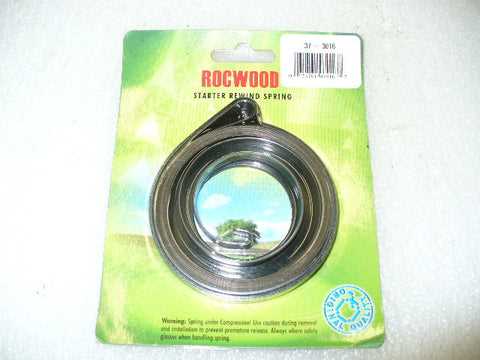
The clutch mechanism is a critical component in the functionality of many mechanical systems, allowing for the controlled engagement and disengagement of power transmission. It plays a key role in managing the rotation of various parts and ensuring smooth operation when transferring energy between different moving elements.
Understanding how this system works can greatly aid in maintaining optimal performance. Below are the main elements and functions:
- Clutch Drum: This part houses the rotating elements and connects to the drive system.
- Springs: Springs play a vital role in ensuring tension control, allowing engagement when the system is in motion.
- Shoes: These provide friction and grip, engaging with the drum to transmit energy when the mechanism is activated.
- Release Mechanism: Allows for the disengagement of the system, preventing unwanted motion.
Each of these elements must work together seamlessly to ensure efficient operation. Regular checks and maintenance of these components can prevent common issues and extend the lifespan of the mechanism
Guide Bar and Chain Tensioning
Tensioning the guide bar and chain is crucial for optimal performance and safety in any cutting tool. Proper adjustment ensures efficient operation, reduces wear on components, and minimizes the risk of accidents. Understanding how to effectively tension these elements will not only enhance the longevity of your equipment but also improve cutting efficiency.
Importance of Correct Tension
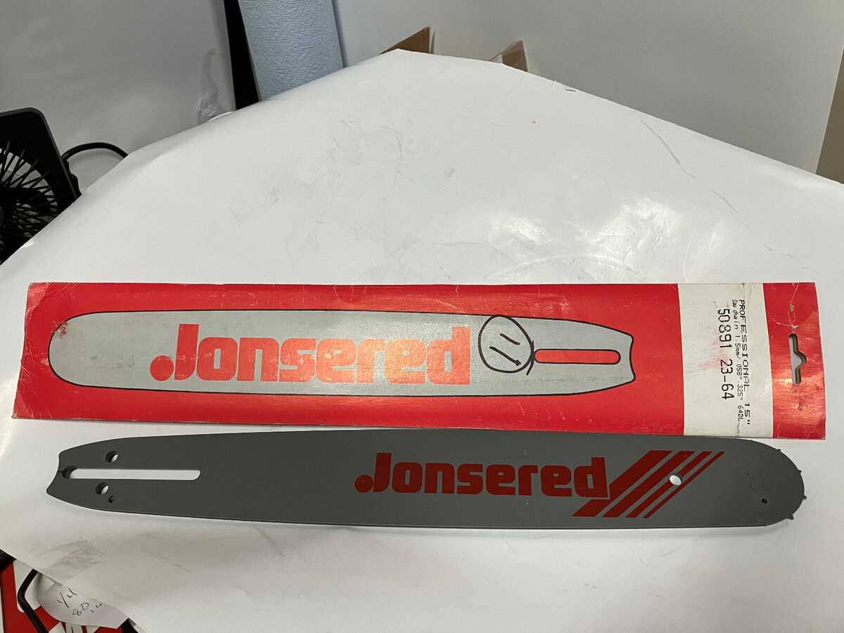
Maintaining the right tension on the guide bar and chain prevents slippage and ensures smooth operation. An overly loose chain can lead to disengagement during use, while a chain that is too tight can cause excessive wear on the drive components and the bar itself. Regularly checking and adjusting the tension will promote better performance and reduce maintenance costs.
How to Adjust Tension
To adjust the tension, follow these simple steps:
- Ensure the tool is powered off and the chain is cool to the touch.
- Locate the tension adjustment screw, usually found on the side of the guide bar.
- Using the appropriate tool, turn the screw clockwise to increase tension or counterclockwise to decrease it.
- Check the tension by pulling on the chain; it should move smoothly but not come off the bar.
- Once satisfied with the tension, securely tighten any locking mechanisms to ensure stability.
Regular checks and adjustments will help maintain peak performance and extend the lifespan of your equipment.
Handle and Throttle Parts Layout
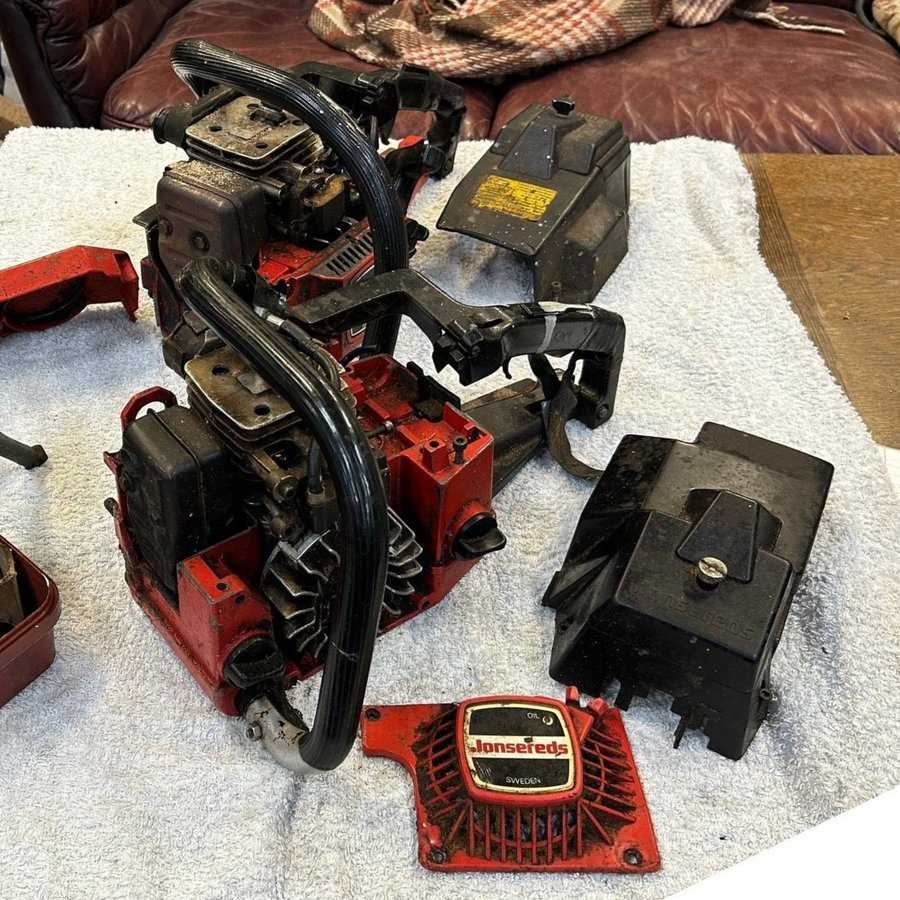
This section provides an overview of the arrangement and configuration of the handle and throttle components found in specific outdoor power equipment. Understanding the layout is essential for effective maintenance and replacement procedures.
Typically, the handle assembly includes various elements that contribute to user control and functionality. Here are the primary components:
- Throttle Trigger
- Handle Grip
- Control Lever
- Mounting Bracket
- Wiring Harness
Each component plays a vital role in ensuring the equipment operates smoothly and efficiently:
- Throttle Trigger: This part allows the user to regulate engine speed.
- Handle Grip: Provides a comfortable and secure hold for the operator.
- Control Lever: Enables quick adjustments to power settings.
- Mounting Bracket: Secures the assembly to the main frame of the device.
- Wiring Harness: Connects electrical components for smooth functionality.
Familiarity with the arrangement of these components aids in diagnosing issues and performing repairs effectively.
Ignition System and Wiring Diagram
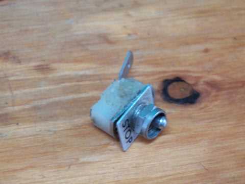
The ignition mechanism plays a crucial role in the operation of small engines, ensuring efficient combustion and reliable performance. Understanding the wiring configuration associated with this system is essential for maintenance and troubleshooting. This section outlines the essential components and their connections, aiding users in visualizing the overall setup.
Key components of the ignition assembly include:
- Ignition coil
- Spark plug
- Flywheel magnet
- Wiring harness
- Kill switch
In this section, we will explore the electrical connections and functional relationships between these elements:
- Ignition Coil: Converts battery voltage into a high-voltage current needed to generate a spark.
- Spark Plug: Ignites the air-fuel mixture in the combustion chamber.
- Flywheel Magnet: Provides the necessary magnetic field for the ignition coil to operate.
- Wiring Harness: Facilitates the electrical connections between components.
- Kill Switch: Ensures safety by stopping the engine when activated.
By following the outlined connections and understanding the roles of each component, users can effectively diagnose and repair any issues related to the ignition system. Proper wiring and functionality are vital for the overall performance of the engine.
Maintenance of the Air Filtration Unit
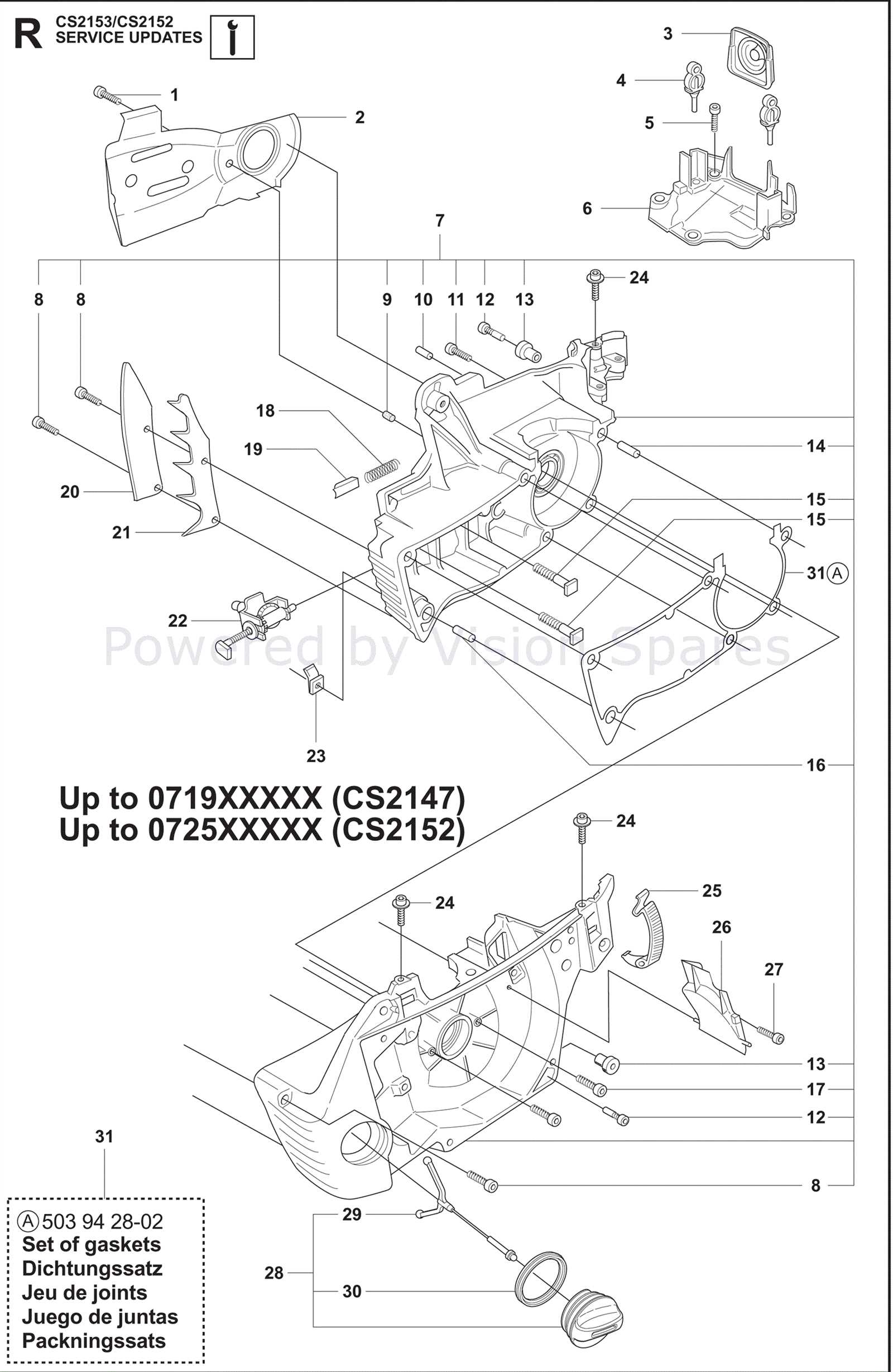
Proper upkeep of the air filtration system is crucial for ensuring optimal engine performance and longevity. Regular maintenance helps prevent dust and debris accumulation, which can hinder airflow and negatively impact the engine’s efficiency. This section outlines essential steps to maintain the filtration unit effectively.
Regular Inspection and Cleaning
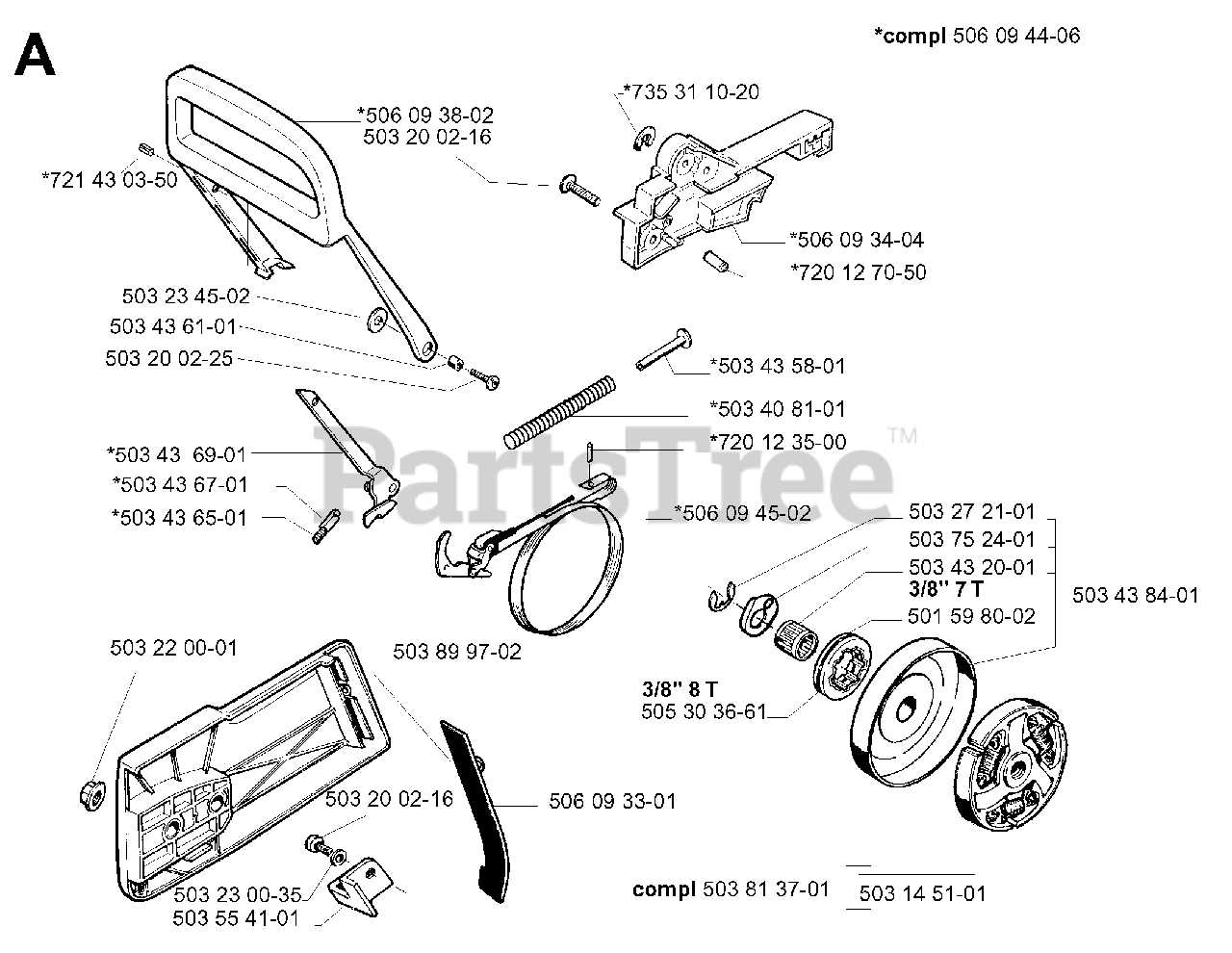
Routine checks of the air filter should be conducted to assess its condition. Remove the filter from the housing and visually inspect it for dirt or damage. If dirt is present, it can be cleaned using compressed air or a soft brush. In cases of excessive wear or irreparable damage, replacement is necessary to maintain air quality.
Replacing the Filter
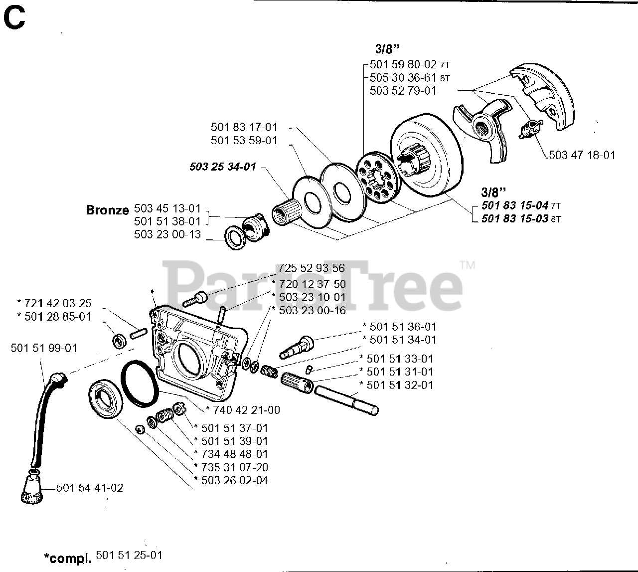
To ensure the best performance, it is recommended to replace the air filter at regular intervals, as specified by the manufacturer. A fresh filter not only enhances airflow but also protects the engine from contaminants. Always consult the owner’s manual for specific replacement guidelines and part numbers to ensure compatibility.
Oil Pump and Lubrication System
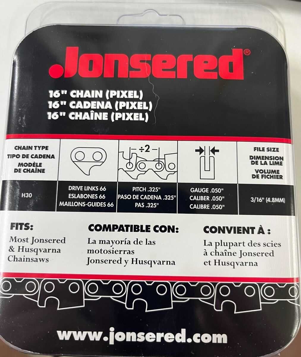
The efficiency of any engine greatly relies on a well-designed mechanism for delivering and managing lubricant. This system ensures that vital components receive adequate oil flow, reducing friction and wear, while maintaining optimal operating temperatures. Understanding the intricacies of this mechanism is crucial for the longevity and performance of the equipment.
Functionality of the Lubrication System
The lubrication system plays a pivotal role in safeguarding engine integrity by ensuring proper oil circulation. It facilitates the transfer of lubricant to critical areas, allowing for smooth operation and preventing overheating. Regular maintenance of this system is essential to avoid potential failures and to ensure the machine operates efficiently.
Components and Maintenance Considerations
The key elements of this system include the pump, oil reservoir, and various channels for oil distribution. Each part must function harmoniously to achieve the desired performance. Regular checks and timely replacements of worn components are vital for sustaining functionality and avoiding costly repairs. Proper lubrication practices contribute to enhanced durability and reliability of the machinery.
Starter Assembly Parts Breakdown
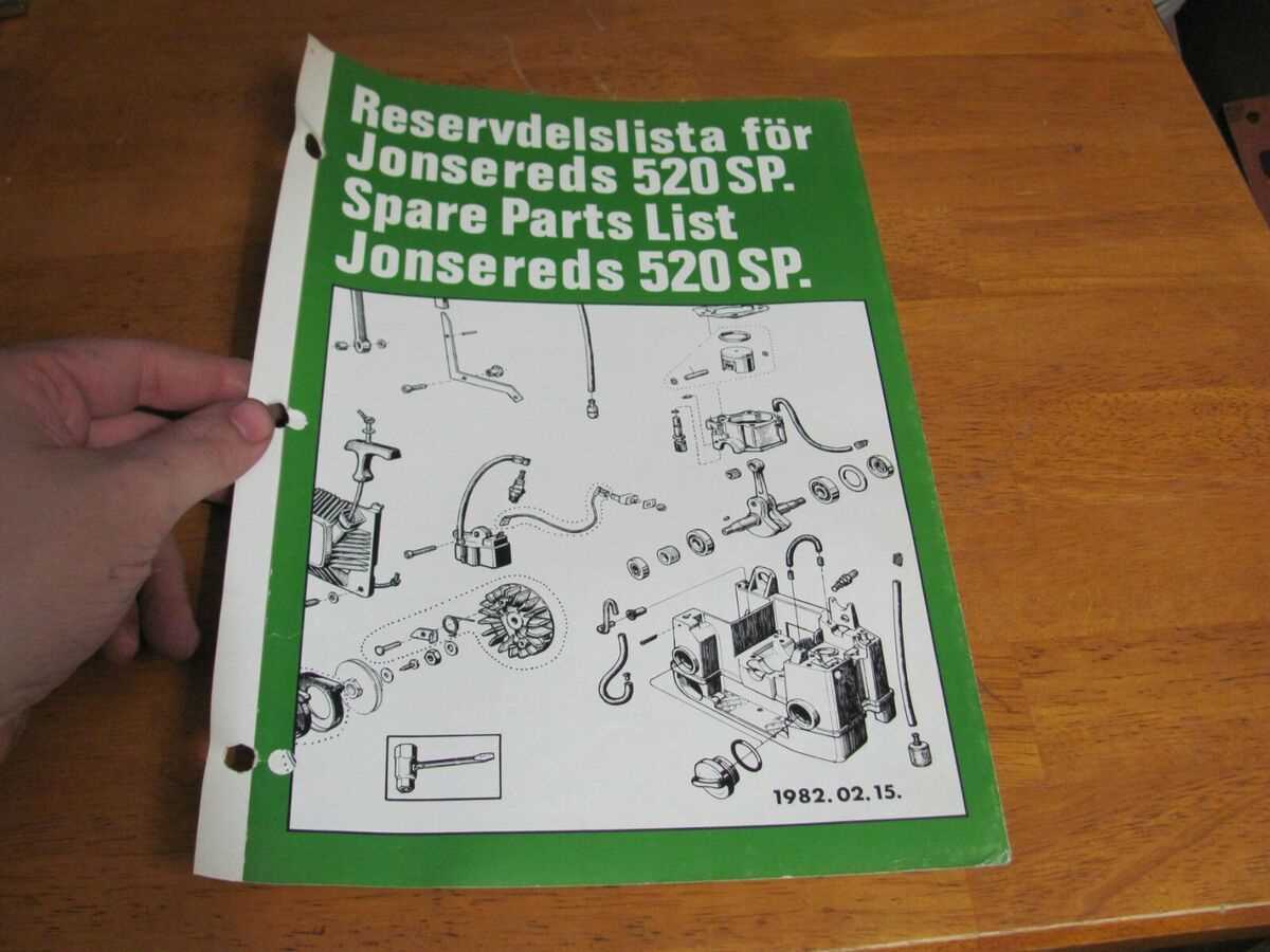
In this section, we will delve into the components that make up the starter assembly, offering a detailed examination of each part’s role and functionality. Understanding these elements is crucial for maintenance and troubleshooting purposes, ensuring optimal performance of your equipment.
Key Components: The starter assembly comprises several critical parts, each contributing uniquely to the starting mechanism’s operation. By identifying and comprehending these components, users can effectively address issues such as starting failures or performance inconsistencies.
Exploring Functionality: By exploring the functionality of each part within the starter assembly, users gain insights into how these components interact and facilitate the starting process. This breakdown enhances comprehension and aids in the accurate diagnosis of any operational issues.
Replacing the Muffler and Exhaust System
In this section, we will explore the process of replacing the component responsible for directing combustion gases away from the engine and reducing noise emissions. The muffler, along with its associated exhaust system, plays a crucial role in maintaining engine performance and noise levels within acceptable limits.
| Step | Description |
| 1 | Locate the muffler and exhaust assembly on your equipment. |
| 2 | Ensure the engine is cool before beginning work to avoid burns. |
| 3 | Use appropriate tools to detach any securing bolts or clamps holding the old muffler in place. |
| 4 | Carefully remove the old muffler and inspect it for any signs of damage or wear. |
| 5 | Install the new muffler, ensuring it is securely fastened with bolts or clamps. |
| 6 | Reattach any heat shields or other components that were removed during the process. |
| 7 | Start the engine and check for proper operation and any unusual noises or vibrations. |
By following these steps, you can effectively replace the muffler and exhaust system, ensuring optimal engine performance and noise reduction.