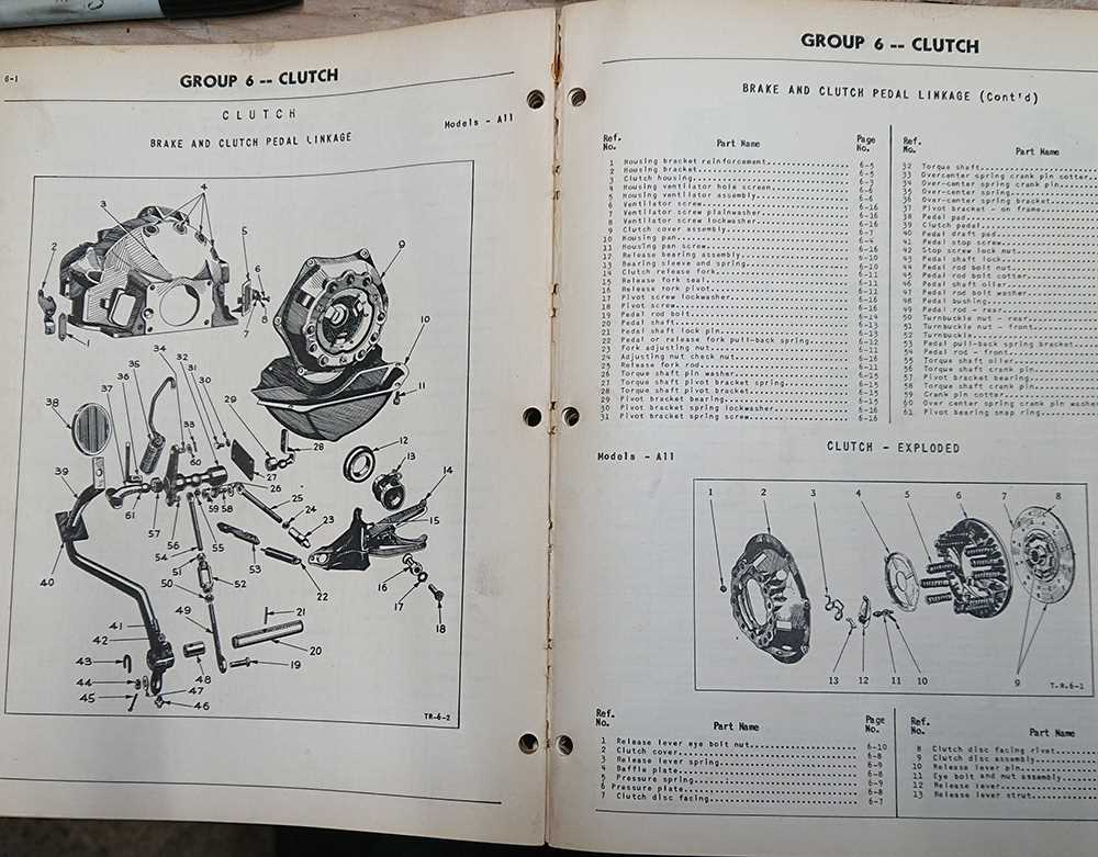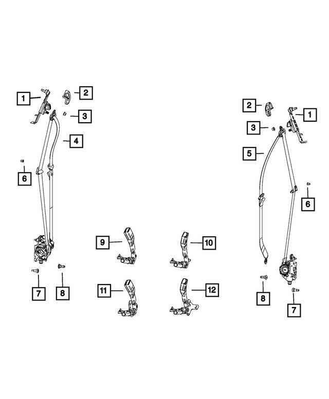
Understanding how different elements of a vehicle are assembled is crucial for those involved in repairs and maintenance. A clear visual representation of individual units and how they connect to form larger systems can significantly streamline the process. This helps both professionals and enthusiasts carry out tasks with greater precision.
These schematics offer a comprehensive overview of the internal structure, ensuring that every connection and detail is accounted for. With accurate illustrations, even the most intricate assemblies become easier to comprehend, making disassembly and reassembly more efficient.
Whether you’re troubleshooting a malfunction or planning routine maintenance, having access to a well-organized visual reference is essential. This approach minimizes errors and saves time, allowing you to focus on what truly matters–getting the vehicle back on the road in optimal condition.
Understanding Vehicle Component Schematics
Interpreting the layout and structure of mechanical component blueprints is essential for effective maintenance and repair. These visual guides help identify individual elements and their connections, offering a clear representation of how various systems function together. Knowing how to read these schematics is invaluable for troubleshooting and ensuring compatibility during repairs.
Key details within these diagrams reveal the precise positioning and interaction between the components, highlighting areas that require attention. By understanding these illustrations, one can efficiently navigate through the assembly process and optimize vehicle performance.
How to Read Chrysler Diagrams Effectively
Understanding the layout of technical illustrations is crucial for anyone working with vehicle maintenance. These visual guides provide a clear and organized way to pinpoint components, connections, and systems in a structured format. Learning how to navigate these schematics efficiently can save time and prevent errors during repairs.
Identifying Key Symbols
The first step in interpreting automotive illustrations is recognizing the symbols used. Each icon or shape represents a specific part or connection. Familiarize yourself with common indicators, such as those for electrical systems, fluids, and mechanical links, to improve accuracy in diagnosing issues.
Using a Step-by-Step Approach
When faced with a detailed graphic, it’s best to break down the information step by step. Start by locating the primary section you’re focusing on, then move outward to understand the related components. This method allows for a more systematic approach, reducing the likelihood of oversight.
| Symbol | Description | ||||||||||||||||||||||||||||||||||||
|---|---|---|---|---|---|---|---|---|---|---|---|---|---|---|---|---|---|---|---|---|---|---|---|---|---|---|---|---|---|---|---|---|---|---|---|---|---|
| Circle with a line | Represent
Key Components in Chrysler Vehicle Schematics
Understanding the primary elements found in technical layouts of vehicles helps ensure efficient repairs and maintenance. These schematics outline various systems and their interrelated parts, making it easier to identify crucial areas that require attention. Whether it’s electrical connections or mechanical components, these illustrations provide essential insights into the vehicle’s overall design and functionality.
Common Symbols Found in Chrysler DiagramsWhen examining technical illustrations for vehicles, it’s essential to understand the various symbols that appear within these representations. These icons are often used to simplify complex systems, allowing for quicker identification of components, functions, and connections. Familiarity with these visual cues can greatly enhance the efficiency of interpreting detailed schematics and instructions. Electrical SymbolsMany illustrations incorporate a range of electrical symbols to represent wiring, fuses, and connections. A simple line may indicate a wire, while more intricate shapes can refer to circuits, switches, and relays. These notations help distinguish between power sources, grounding points, and other critical elements of the system. Mechanical SymbolsMechanical elements also have their unique set of symbols. For example, arrows often denote movement or direction of force, while specific shapes like circles and triangles may signify different parts of the system. Recognizing these symbols ensures a better understanding of the physical interactions within the system. Locating Specific Parts in Chrysler SchematicsWhen working with automotive blueprints, understanding how to identify individual components can significantly improve efficiency. A clear grasp of the layout and symbols within these technical drawings is essential for anyone involved in maintenance or repairs. By learning to navigate the schematics effectively, you can save time and avoid confusion. Understanding the StructureThe first step is to become familiar with how these visual guides are organized. Typically, they follow a logical sequence, with each section dedicated to a particular system. Recognizing key markers within these documents will allow you to pinpoint the exact element needed, whether it’s related to electrical circuits, engine layout, or other areas. Using Search TechniquesTo locate a specific component quickly, cross-referencing between sections is crucial. Many schematics include indices or key codes, which can be invaluable tools for tracking down the right section. Knowing how to use these resources will streamline the process and ensure accurate results. Importance of Accurate Diagrams for RepairsPrecise illustrations play a crucial role in the maintenance and restoration of vehicles. They serve as visual guides, offering detailed representations that facilitate the understanding of complex components and systems. When working on repairs, having access to reliable schematics ensures that technicians can perform their tasks efficiently and accurately, minimizing the risk of errors. Accurate visual representations not only enhance the repair process but also contribute to safety and longevity. By following detailed guides, mechanics can identify potential issues early and implement effective solutions, thus preventing further damage. Furthermore, clear illustrations assist in ensuring that all necessary steps are followed systematically, promoting a thorough understanding of the assembly and disassembly processes.
Differences Between Various Chrysler Models
The diversity among different vehicle models from a single manufacturer reveals significant variations in design, performance, and functionality. Understanding these distinctions can aid consumers in making informed choices that align with their preferences and needs. Performance Variations
Engine specifications and handling characteristics can differ markedly across models. Here are some key aspects:
Interior FeaturesInterior amenities and layout can also vary significantly. Consider the following:
Electrical Systems and Their RepresentationThe intricate network of electrical systems in vehicles plays a vital role in ensuring optimal performance and functionality. Understanding how these systems are depicted can greatly aid in diagnosing issues and facilitating repairs. This section delves into the various components of electrical networks and how they are represented in schematics, providing clarity for technicians and enthusiasts alike. Components OverviewElectrical systems consist of various components, including batteries, alternators, starters, and wiring harnesses. Each element interacts within the network to ensure efficient energy distribution and functionality of the vehicle’s electrical features. Schematic RepresentationElectrical schematics serve as visual guides that simplify the complex relationships between various components. These representations utilize standardized symbols to depict parts and their connections, enabling a clearer understanding of the overall system. Below is an example of common symbols used in electrical schematics:
Transmission Diagrams for Chrysler VehiclesUnderstanding the layout and components of vehicle transmission systems is essential for effective maintenance and repair. This section provides valuable insights into the structure and functionality of these crucial systems, allowing enthusiasts and technicians to identify specific elements and their interactions. Key Components of Transmission SystemsModern automotive transmission systems comprise several vital parts that work together to ensure smooth operation. Familiarity with these components is crucial for anyone involved in vehicle maintenance.
Benefits of Understanding Transmission Layouts
Grasping the arrangement and function of these systems offers several advantages:
Visualizing the Chrysler Brake System
The braking mechanism in vehicles plays a crucial role in ensuring safety and control. Understanding its components and how they function together is essential for effective maintenance and troubleshooting. This section aims to provide a clear visualization of the braking assembly, highlighting its key elements and their interrelations. Key Components of the Braking Mechanism
The braking system comprises several vital elements, each contributing to the overall functionality. Familiarizing oneself with these components allows for better comprehension of how the system operates. Below is a summary of the primary parts involved:
Understanding the FunctionalityEach component of the braking assembly interacts with others to produce effective deceleration. When the brake pedal is pressed, it activates the master cylinder, generating hydraulic pressure that travels through the brake lines. This pressure pushes the brake calipers, which in turn compress the pads against the rotor, creating friction and slowing down the vehicle. Familiarity with this process aids in identifying potential issues and performing necessary repairs. Cooling System Layout in Chrysler Schematics
The cooling system is a crucial component of an engine’s efficiency and longevity. It plays a vital role in regulating temperature, preventing overheating, and maintaining optimal performance. Understanding the configuration of this system is essential for diagnosing issues and ensuring the smooth operation of the vehicle. Key Components of the Cooling ArrangementWithin this system, several fundamental elements work together to manage heat. The radiator serves as the primary heat exchanger, dissipating excess temperature from the coolant. The water pump circulates the fluid, ensuring even distribution throughout the engine. Additionally, the thermostat regulates the flow based on temperature, allowing for efficient operation under various conditions. Flow Path and Circuit DesignThe design of the cooling circuit is critical for maintaining engine temperature. The coolant travels from the engine to the radiator, where it is cooled by air passing through the fins. This flow path minimizes hotspots and ensures the engine operates within the desired range. Proper layout enhances efficiency and contributes to the overall reliability of the system. How to Use Diagrams for Parts OrderingUtilizing visual representations can greatly simplify the process of ordering components for your vehicle. By following specific guidelines, you can ensure accurate identification and selection of the necessary items, leading to a smoother repair or maintenance experience. Understanding the Visual AidsBefore placing an order, familiarize yourself with the visual aids available. Here are some steps to consider:
Effective Ordering ProcessOnce you have a clear understanding of the visual aids, follow these steps to order components effectively:
By following these guidelines, you can enhance your experience and efficiency in sourcing the right components for your vehicle. Chrysler Engine Assembly BreakdownThis section provides an overview of the components and structure involved in the assembly of the powertrain. Understanding the organization and interaction of these elements is essential for effective maintenance and repair. Each component plays a vital role in the overall functionality of the engine, influencing performance and reliability. Key ComponentsThe primary elements within the assembly include the block, cylinder head, crankshaft, and pistons. Each part must be precisely designed and manufactured to ensure optimal operation. The coordination between these components is crucial for achieving the desired power output and efficiency. Assembly ProcessThe assembly process typically involves several critical steps, including alignment, fastening, and sealing. Proper techniques during assembly can prevent leaks and ensure durability. Additionally, adherence to specifications is necessary to maintain the integrity of the entire system. |
