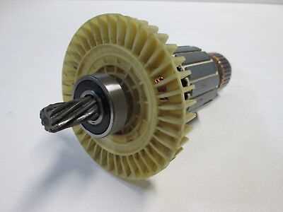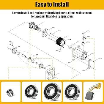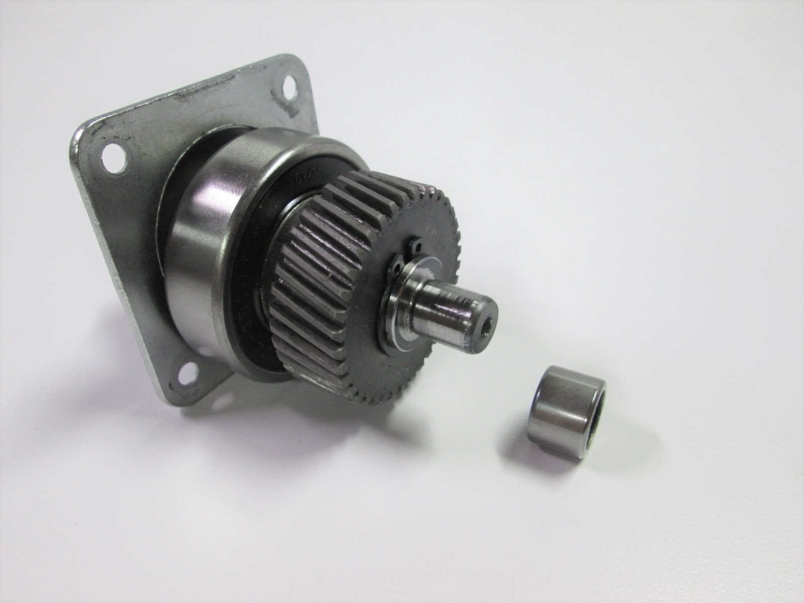
Understanding the layout of various mechanical elements is essential for ensuring smooth operation and timely maintenance of any system. By examining the detailed structure of these components, one can easily grasp how each part contributes to the overall functionality.
Each element in a mechanical setup has a specific role, and visualizing their arrangement helps in identifying potential issues and optimizing performance. A well-illustrated representation of these parts allows for a more efficient approach to both repairs and upgrades, making it easier to keep systems running reliably.
Whether for regular upkeep or troubleshooting, knowing the precise configuration of elements within a system is a fundamental aspect of maintaining its longevity and efficiency. It provides a clear understanding of how to approach various technical tasks with greater confidence and accuracy.
Rm871 Motor Parts Diagram
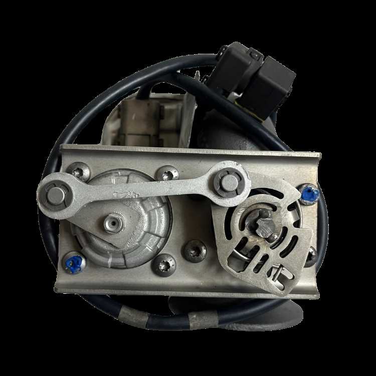
The system of components responsible for the functionality of mechanical devices often involves a variety of interconnected elements. Understanding the layout of these components is crucial for efficient maintenance and repair. A well-structured illustration of such components helps users quickly identify and address issues within the mechanism.
| Component | Function | ||||||||||||||||||||||||||||||
|---|---|---|---|---|---|---|---|---|---|---|---|---|---|---|---|---|---|---|---|---|---|---|---|---|---|---|---|---|---|---|---|
| Main Element | Primary driver of the mechanical operation, responsible for initiating the movement within the device. | ||||||||||||||||||||||||||||||
| Secondary Mechanism | Works in coordination with the primary element, providing additional support to enhance performance. | ||||||||||||||||||||||||||||||
| Connecting Elements | Ensure stability and proper interaction between
Overview of the Motor’s Main ComponentsThe mechanism consists of several critical elements that work together to ensure optimal performance. Each part has a unique function, contributing to the overall efficiency and reliability of the system. Understanding these components helps in maintaining and troubleshooting potential issues, ensuring the smooth operation of the device.
Placement of Bearings and ShaftsThe positioning of rotational components is crucial for the efficient operation of any mechanism. Proper alignment ensures minimal friction, optimal performance, and longevity of the system. Understanding the relationship between these elements is essential for effective assembly and maintenance. Bearings serve as support structures, allowing shafts to rotate smoothly. Their placement affects not only the stability of the shafts but also the overall functionality of the entire assembly. Key considerations include:
Several factors influence the optimal arrangement:
Regular inspections and adjustments may be necessary to maintain the ideal configuration, ensuring that each element functions harmoniously within the assembly. Cooling System Components in the MotorThe efficiency and longevity of a machine largely depend on its ability to manage heat effectively. A well-designed cooling system is crucial for maintaining optimal operating temperatures, preventing overheating, and ensuring overall performance. This section explores the various elements that contribute to effective temperature regulation in such systems.
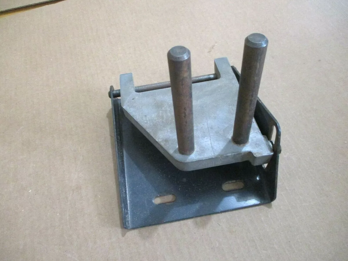
Each of these components plays a vital role in the cooling system, working together to ensure that the machinery operates efficiently and reliably under various conditions. Regular maintenance and inspection of these elements can prevent overheating and extend the service life of the entire system. Mounting and Support Structures OverviewThe foundation and supporting frameworks play a crucial role in ensuring the stability and performance of mechanical systems. These structures not only provide essential support but also contribute to the overall efficiency of the assembly. Understanding their design and function is vital for effective implementation and maintenance. Key Components: Typically, the mounting and support frameworks consist of various elements such as brackets, frames, and fasteners. Each component serves a specific purpose, allowing for optimal alignment and securing of the system in place. Considerations for Design: When designing these structures, factors such as load distribution, vibration dampening, and material selection must be taken into account. Properly designed support systems can significantly enhance the longevity and reliability of the entire assembly. Detailed View of Motor’s Control UnitThis section delves into the intricate components that govern the operation of the driving mechanism. Understanding the control unit is essential for grasping how these systems achieve optimal performance and efficiency. Each element plays a vital role in ensuring seamless functionality, and a comprehensive analysis reveals their interconnected nature. Key Components of the Control UnitThe control unit consists of several integral components that work in harmony to manage the performance of the system. Below is a table highlighting these components along with their respective functions:
Operational InsightsAnalyzing how these components interact provides valuable insights into system reliability and efficiency. The processor interprets data from the sensors and adjusts performance accordingly, ensuring that the entire system operates within designated parameters. This synergy not only enhances functionality but also contributes to the longevity of the equipment. How to Read the Parts Diagram EfficientlyUnderstanding technical illustrations is crucial for effective maintenance and assembly. By familiarizing yourself with the layout and symbols used in these representations, you can streamline your workflow and enhance your troubleshooting skills. This section provides insights into techniques that will help you navigate these visuals with ease. Familiarize Yourself with SymbolsEach illustration contains specific symbols and notations that correspond to various components. Take time to study the legend or key, which typically accompanies the visual representation. Recognizing these symbols will allow you to quickly identify parts and understand their functions. Break It Down into SectionsRather than attempting to comprehend the entire illustration at once, divide it into smaller sections. Focus on one area at a time, ensuring you grasp the relationships and connections between components. This methodical approach can help prevent confusion and make the information more digestible. Common Symbols Used in Motor DiagramsUnderstanding the various symbols utilized in technical schematics is crucial for effective interpretation and analysis. These representations serve as a universal language, enabling engineers and technicians to communicate complex ideas efficiently. Familiarity with these icons simplifies the process of troubleshooting and enhances overall comprehension. Below are some frequently encountered symbols and their meanings:
Recognizing these symbols can greatly facilitate the understanding of electrical systems and enhance problem-solving capabilities. |
