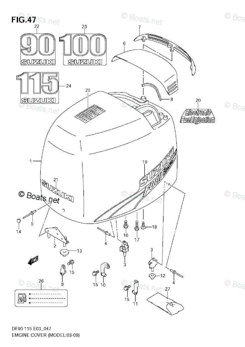
When it comes to maintaining marine machinery, having a clear view of its various components is essential. A comprehensive visual representation can greatly assist in identifying the necessary elements for service and repair. By utilizing detailed schematics, users can navigate through the intricate assembly of their outboard motors with ease.
Such illustrations not only facilitate the identification of each individual component but also aid in understanding how they interact within the system. This knowledge is vital for both troubleshooting issues and performing routine maintenance. Whether you’re a seasoned technician or a boating enthusiast, grasping the layout of the machinery is key to ensuring optimal performance.
Moreover, having access to precise representations can save time and prevent potential errors during repairs. By accurately pinpointing parts, you can streamline the process and enhance the longevity of your equipment. Emphasizing the importance of these visual guides empowers users to take a proactive approach to maintenance and care.
Engine Components Overview
This section provides a comprehensive look at the essential elements that make up a marine propulsion unit. Understanding these components is vital for anyone looking to maintain or troubleshoot their engine effectively. Each part plays a crucial role in ensuring optimal performance and reliability during operation.
The primary assemblies include the powerhead, which houses the core mechanisms that generate thrust. Attached to this are the fuel delivery and ignition systems, which are responsible for managing the engine’s energy output efficiently. Additionally, the cooling system is crucial, as it prevents overheating and maintains the engine’s longevity.
Moving to the lower unit, this area contains the drive mechanism, which translates rotational force into movement. It is essential to monitor the condition of these components regularly, as wear and tear can lead to performance issues or even complete failure.
In summary, a thorough understanding of these elements enables better maintenance practices and contributes to the overall longevity of the vessel’s propulsion system. Ensuring each component functions correctly is key to achieving optimal efficiency and reliability.
Main Systems of the Suzuki DF90 Motor
The internal mechanisms of an outboard engine are crucial for its efficient operation and performance. Understanding the key systems that work in harmony allows for better maintenance and troubleshooting, ensuring longevity and reliability in various marine conditions.
One of the primary components is the fuel delivery system, which is responsible for supplying the engine with the necessary fuel mixture for combustion. This system includes fuel pumps, filters, and injectors that work together to optimize performance and reduce emissions.
Another essential system is the cooling mechanism, which prevents overheating during operation. This involves a combination of water intake, pumps, and passages that circulate coolant around the engine, maintaining an ideal temperature for optimal functioning.
The ignition system also plays a vital role, ensuring timely and efficient combustion of the fuel-air mixture. It consists of components such as spark plugs, coils, and ignition timing systems that create a powerful spark to ignite the fuel, enhancing engine responsiveness.
Lastly, the lubrication system minimizes friction between moving parts, reducing wear and tear. This system ensures that oil is circulated throughout the engine, keeping it running smoothly and efficiently, thereby extending the lifespan of the entire unit.
Understanding the Cooling System Layout
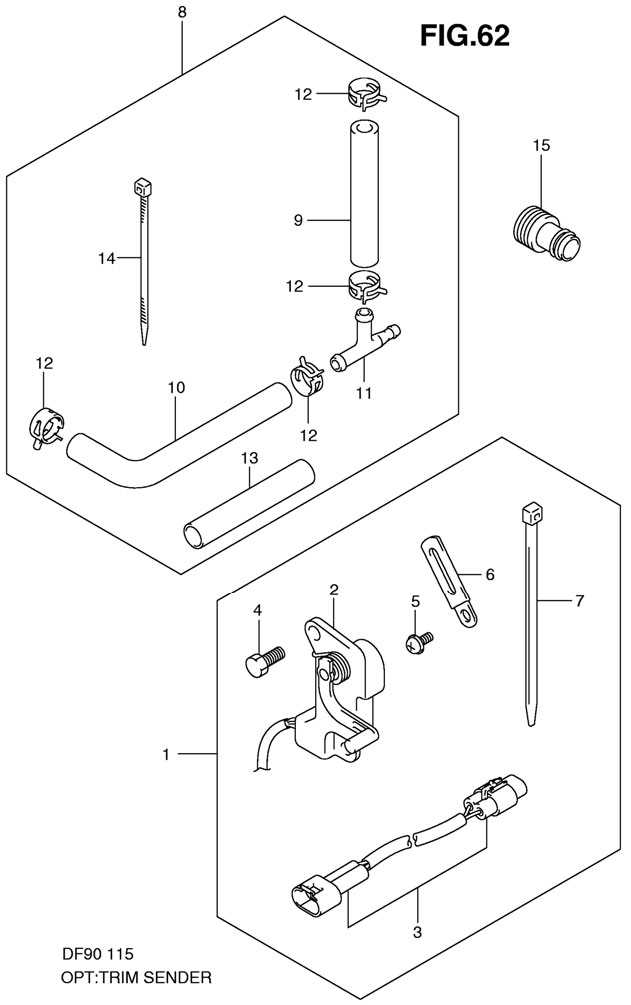
The cooling system is a vital component of any marine engine, ensuring that the internal temperatures remain within optimal limits during operation. Proper heat management is essential for maintaining performance and longevity. This section will explore the essential elements and arrangement of the cooling system, highlighting its significance in overall engine efficiency.
Key Components of the Cooling System
- Water Pump: Responsible for circulating coolant throughout the system, maintaining a steady flow.
- Heat Exchanger: Transfers heat from the engine to the surrounding water, effectively dissipating excess heat.
- Thermostat: Regulates the flow of coolant based on temperature, ensuring optimal engine warmth.
- Cooling Hoses: Transport coolant to and from various components, designed to withstand high pressure and temperature.
Understanding Flow Direction
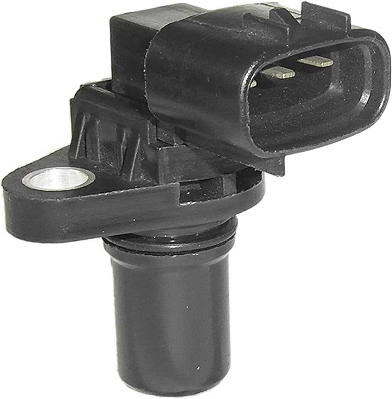
To comprehend the efficiency of the cooling system, it’s essential to recognize the flow direction of the coolant. The following steps outline this process:
- Coolant is drawn from the water source through the intake.
- The water pump propels the coolant towards the engine.
- As the engine operates, the coolant absorbs heat and becomes warmer.
- The heated coolant then moves to the heat exchanger.
- After cooling, the coolant returns to the engine, completing the cycle.
Understanding the arrangement and functionality of the cooling system is crucial for effective maintenance and troubleshooting. Regular checks and appropriate servicing ensure that the system operates efficiently, contributing to the overall reliability of the engine.
Fuel Supply Line and Injection Assembly
The fuel supply line and injection assembly play a crucial role in the overall performance of marine engines. This system ensures the efficient delivery of fuel to the combustion chamber, optimizing engine functionality and enhancing operational reliability. Understanding the components and their interactions within this assembly is essential for effective maintenance and troubleshooting.
Components of the Fuel Supply System
- Fuel Pump: Responsible for transporting fuel from the tank to the engine.
- Fuel Filters: Designed to remove impurities from the fuel before it reaches the injection system.
- Fuel Lines: Piping that connects various components, facilitating fuel flow.
- Injectors: Devices that atomize fuel and deliver it into the combustion chamber for efficient burning.
Importance of Regular Maintenance
Maintaining the fuel supply and injection assembly is vital for ensuring optimal engine performance. Regular inspections can prevent clogs and leaks, which can lead to significant performance issues. Key maintenance practices include:
- Inspecting fuel lines for wear or damage.
- Replacing fuel filters at recommended intervals.
- Cleaning or replacing injectors to ensure proper atomization of fuel.
Electrical Connections and Wiring Diagram
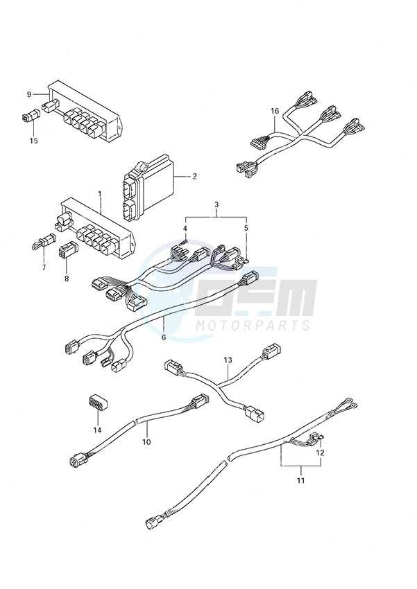
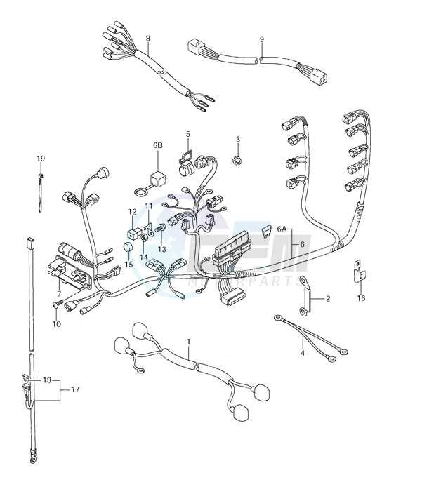
This section provides a comprehensive overview of electrical interconnections and schematics relevant to marine outboard engines. Understanding these systems is crucial for ensuring the optimal performance and safety of the vessel. Proper wiring facilitates the correct functioning of various components, which in turn enhances the overall operation of the engine.
Key Components of Electrical Systems
- Batteries
- Switches
- Fuses
- Wiring Harnesses
- Control Panels
Common Wiring Practices
- Use appropriate gauge wire to prevent overheating.
- Ensure all connections are secure and insulated.
- Label wires for easy identification during maintenance.
- Regularly inspect the wiring for signs of wear or damage.
Adhering to these guidelines will help maintain a reliable electrical system, ultimately contributing to the effective operation of your marine engine.
Throttle and Gear Control Mechanism
The throttle and gear control mechanism plays a crucial role in the overall functionality of marine engines. This system enables the operator to manage the speed and direction of the vessel effectively, ensuring smooth navigation and optimal performance. Understanding its components and operation is essential for maintenance and troubleshooting.
Components of the Control System
This control system comprises various elements that work together to provide precise control over the engine’s functions. The primary components include:
- Throttle lever: Adjusts the engine’s power output.
- Gear shift lever: Changes the transmission settings between forward, neutral, and reverse.
- Cables: Connect the levers to the engine, transmitting the operator’s input.
- Linkage: Transmits movement from the levers to the throttle and gear mechanisms.
Operating Principles
The operation of the throttle and gear control mechanism is based on the interaction between the user inputs and the engine response. When the operator moves the throttle lever, it adjusts the fuel flow, thus altering the engine speed. Simultaneously, shifting the gear lever allows the user to change the propulsion direction. Proper synchronization between these actions ensures optimal performance and efficiency.
Regular inspection and maintenance of the control system components are vital for reliable operation. Ensuring that all cables are correctly adjusted and free of wear can significantly enhance the responsiveness and longevity of the mechanism.
Exhaust Components and Flow Path
The exhaust system plays a crucial role in the overall performance and efficiency of an engine. It is designed to manage the gases produced during combustion, ensuring they are expelled in a manner that minimizes back pressure and optimizes engine function. Understanding the various elements involved in the exhaust process is essential for maintenance and troubleshooting.
Key elements of the exhaust setup include the manifold, which collects gases from the cylinders; the exhaust pipe, which directs the flow towards the outlet; and the muffler, which reduces noise. Each component is strategically positioned to facilitate smooth gas flow while preventing turbulence and obstruction. The pathway of exhaust gases typically begins at the manifold, progresses through the pipes, and ultimately exits through the muffler, where sound dampening occurs.
Additionally, several factors influence the efficiency of this system, such as the design of the components and the materials used in their construction. Properly functioning exhaust components not only improve engine performance but also contribute to environmental compliance by reducing harmful emissions. Regular inspections and timely replacements of worn parts are vital to maintaining optimal exhaust flow and overall engine health.
Lubrication System and Oil Circulation
The lubrication mechanism is vital for maintaining optimal performance and longevity of the engine. It ensures that all moving components receive adequate oil supply, reducing friction and wear during operation. A well-designed circulation system is essential for distributing lubricants effectively throughout the engine, allowing it to function smoothly and efficiently.
This system typically consists of an oil reservoir, pump, and various channels that facilitate the movement of lubricants. The pump plays a crucial role in drawing oil from the reservoir and pushing it through the engine, ensuring that all critical areas are properly lubricated. As the oil circulates, it absorbs heat and carries away contaminants, thus maintaining a clean and efficient engine environment.
Regular maintenance of the lubrication system is necessary to prevent potential failures. Monitoring oil levels, changing filters, and using the correct type of lubricant are essential practices that contribute to the overall health of the engine. By ensuring the lubrication system operates effectively, engine performance can be maximized, and the risk of damage minimized.
Detailed View of the Propeller Assembly
The propeller assembly plays a crucial role in the overall performance of outboard engines. This component is responsible for converting engine power into thrust, enabling efficient movement through water. Understanding its construction and function is essential for optimal operation and maintenance.
Within the assembly, several key elements work in unison to ensure smooth and effective propulsion. Below is a breakdown of these components, their roles, and how they interact with each other.
| Component | Description | Function |
|---|---|---|
| Hub | The central part of the assembly that connects to the engine shaft. | Transfers rotational energy from the engine to the blades. |
| Blades | Flat surfaces that extend from the hub. | Create thrust by pushing water backwards when rotating. |
| Spinner | A covering that enhances aerodynamics and protects the hub. | Reduces drag and improves efficiency. |
| Pin | A small component that helps secure the blades to the hub. | Ensures stability and alignment of the blades during operation. |
Proper maintenance and inspection of the propeller assembly are vital for longevity and performance. Regular checks for wear and damage can prevent more significant issues, ensuring reliable operation in various marine conditions.
Ignition System Structure and Function
The ignition system plays a vital role in the operation of internal combustion engines by providing the necessary spark to ignite the air-fuel mixture in the combustion chamber. This intricate system is designed to ensure reliable performance, contributing significantly to the overall efficiency and power output of the engine. Understanding its components and how they work together can greatly enhance maintenance and troubleshooting efforts.
Key Components of the Ignition System
The ignition system is composed of several essential components, including the ignition coil, distributor, spark plugs, and various sensors. The ignition coil transforms the low voltage from the battery into a high voltage that is essential for generating a spark. This high voltage is directed to the spark plugs via the distributor, which ensures that each cylinder receives the ignition signal at the correct timing. Effective functioning of these components is crucial for optimal engine performance.
Operational Mechanism
The operational mechanism begins with the battery supplying power to the ignition coil. When the coil is energized, it creates a magnetic field, which collapses to generate a high-voltage pulse. This pulse travels through the ignition wires to the spark plugs, igniting the fuel-air mixture in the cylinders. Precise timing of this process is essential, as it directly affects engine efficiency, emissions, and performance. Regular inspection and maintenance of the ignition system components can prevent potential failures and ensure smooth engine operation.
Key Maintenance Areas and Parts Location
Proper upkeep of a marine engine is essential for ensuring its longevity and optimal performance. Understanding the crucial components and their placement within the system allows for efficient maintenance. Regular inspections can help identify potential issues before they escalate, ensuring a smooth boating experience.
Critical Components for Regular Checkups
Among the primary areas that require attention are the fuel system, cooling system, and electrical components. The fuel lines and filters should be routinely examined to prevent clogs that could hinder performance. Additionally, inspecting the cooling system, including the water pump and thermostats, is vital to avoid overheating. Lastly, the electrical connections must be checked for corrosion and secure fit to ensure reliable operation.
Accessing Key Sections for Service
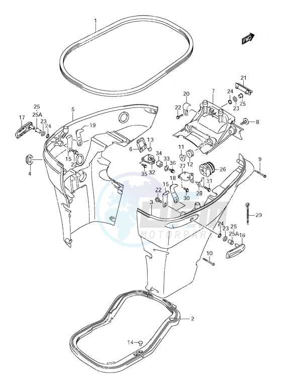
Knowing where to find each component is just as important as understanding its function. Access panels are typically located on the engine cover, allowing for easy reach to filters and oil reservoirs. Furthermore, side panels can provide entry to the cooling components. For electrical systems, tracing wiring harnesses will reveal connectors and fuses that may require attention. Familiarizing oneself with these locations simplifies the maintenance process and enhances overall efficiency.
Power Output and Transmission Parts Layout
This section provides an overview of the components involved in energy delivery and gear mechanisms within outboard engines. Understanding the configuration and interaction of these elements is crucial for optimizing performance and ensuring reliability during operation. The efficient transfer of power from the engine to the propeller is essential for achieving the desired speed and maneuverability on the water.
Key Components Overview
The energy transmission system comprises various elements that work together to convert the engine’s rotational force into propulsion. The main components include the crankshaft, gearbox, and propeller shaft, each playing a vital role in the overall function of the engine. Proper alignment and maintenance of these components are necessary to prevent issues such as vibration and power loss.
Component Layout and Functionality
Below is a simplified layout that illustrates the arrangement of critical elements in the power output and transmission system:
| Component | Function |
|---|---|
| Crankshaft | Converts linear motion from pistons into rotational motion. |
| Gearbox | Modifies torque and speed to optimize engine output. |
| Propeller Shaft | Transfers rotational energy to the propeller for thrust generation. |
| Coupling | Connects the engine to the gearbox, allowing for torque transfer. |
| Propeller | Transforms rotational energy into forward motion. |