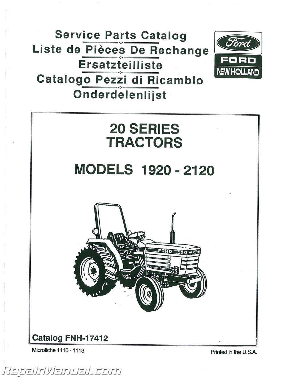
In the world of automotive engineering, comprehending the intricate relationships between various elements is crucial for maintaining and enhancing performance. Each vehicle consists of multiple mechanisms that work together to ensure optimal functionality, from the engine to the electrical systems. A thorough grasp of these components allows for informed decisions when it comes to repairs, upgrades, and general upkeep.
By examining the interconnections and roles of different elements, enthusiasts and professionals alike can foster a deeper appreciation for the technology that drives modern transportation. This exploration not only aids in troubleshooting issues but also enhances the overall driving experience by ensuring that each part operates harmoniously within the system.
Furthermore, understanding these essential mechanisms empowers individuals to engage more confidently in discussions related to automotive advancements. As technology continues to evolve, a solid foundation in the core components becomes increasingly valuable, paving the way for innovative solutions and enhancements in vehicle design.
This section aims to provide a comprehensive understanding of how various components are represented visually within automotive schematics. Such illustrations are essential for both enthusiasts and professionals, as they facilitate a deeper comprehension of vehicle assembly and maintenance. A clear layout of elements not only aids in identification but also enhances the overall efficiency of repair and diagnostics.
Importance of Visual Representation
Visual aids serve a crucial role in simplifying complex information. They allow individuals to:
- Quickly locate components
- Understand the relationship between different elements
- Improve accuracy during assembly or repairs
Types of Illustrative Guides
There are several formats used to depict various elements, including:
- Exploded views: Show components separated from each other for clarity.
- Assembly charts: Outline the order and method for putting components together.
- Wiring schematics: Detail the electrical connections between different parts.
Understanding Diagram Components
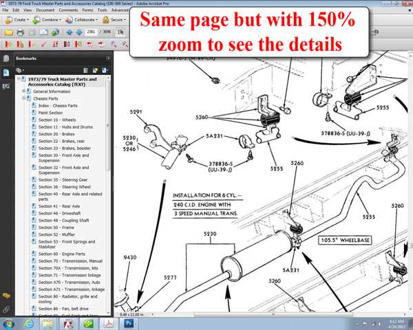
Comprehending the elements that constitute a schematic representation is essential for effective analysis and application. Each element plays a crucial role in conveying information and aiding in the interpretation of the overall structure and function of the system in question. This section aims to elucidate the significance of these components and how they interact with one another.
Key Elements of Schematic Representations
Symbols serve as the foundational building blocks of any schematic. They represent various entities, from mechanical components to electrical systems. Understanding the meaning behind each symbol is vital for accurate interpretation. Additionally, lines connect these symbols, illustrating relationships and pathways between different elements, enabling a clearer understanding of how each part operates within the larger framework.
Interpreting Relationships
Recognizing the interactions between different components is fundamental for troubleshooting and enhancing functionality. Each connection indicated by lines reflects an operational relationship, often representing flow or directionality. Analyzing these connections can reveal potential issues and inform necessary adjustments to optimize performance.
Importance of Accurate Diagrams
Clear and precise visual representations play a crucial role in understanding complex mechanical systems. They serve as visual roadmaps, guiding both technicians and enthusiasts through intricate configurations and operational details. Accurate diagrams enhance comprehension by illustrating component relationships, functionality, and assembly sequences with clarity.
Enhanced Understanding and Efficiency
Accurate diagrams facilitate enhanced understanding, enabling technicians to navigate the complexities of system configurations with greater efficiency. By providing detailed views of interconnected components and their functions, these diagrams streamline troubleshooting and maintenance processes.
Precision in Implementation
Precision in diagrams ensures precise implementation of assembly and repair procedures. Technicians rely on these visual aids to avoid errors during part replacement and system reconfiguration, thereby minimizing downtime and optimizing operational reliability.
How to Read Automotive Schematics
Understanding the structure of vehicle schematics is essential for anyone working with or repairing complex machinery. These diagrams provide a visual representation of how various components are connected and function together, making it easier to trace connections and resolve issues.
Identifying Key Symbols
Automotive schematics rely on standardized symbols to represent individual elements. Recognizing these icons, such as those for electrical connections, switches, and sensors, helps to quickly interpret how each part fits into the larger system. Mastering these symbols is crucial for effective troubleshooting and repairs.
Following Wire Paths
The connections between different components are often shown as lines representing wires. By carefully tracing these lines, you can determine the route of electrical signals and how power is distributed across the system. This method allows for a deeper understanding of how the entire network functions together.
Common Symbols in Ford Diagrams
Understanding the various symbols used in vehicle schematics is essential for anyone involved in maintenance or repair. These representations simplify the interpretation of technical drawings and help to locate components more efficiently.
Electrical Symbols
Electrical schematics often include a variety of symbols that represent key elements in the system, such as fuses, resistors, and relays. These icons help to quickly identify connections and components, making it easier to troubleshoot wiring and power-related issues. A solid grasp of these symbols is crucial for diagnosing electrical problems.
Mechanical Symbols
Mechanical symbols are used to represent moving parts, joints, and connections in the design. These include indicators for gears, pulleys, and other crucial elements of the machinery. Recognizing these symbols ensures proper assembly and disassembly of the mechanical components.
Applications in Repair and Maintenance
When working on vehicle upkeep or resolving technical issues, a comprehensive understanding of various components is essential. This knowledge allows mechanics and enthusiasts alike to efficiently address common issues and improve overall performance. By employing structured resources and technical insights, individuals can streamline the repair process, minimizing time and potential errors.
Streamlining Troubleshooting
Accurate identification of faulty elements plays a pivotal role in resolving mechanical failures. Utilizing well-organized guides and resources makes it easier to pinpoint specific malfunctions, ensuring that the right steps are taken for timely repairs. This not only increases efficiency but also helps in preventing recurring issues.
Optim
Online Resources for Diagrams
Accessing detailed visuals and information for various components can greatly simplify the process of understanding complex systems. Multiple online platforms offer extensive libraries of technical visuals, making it easier to find the exact information needed for different models and assemblies. Whether for maintenance or upgrades, these resources provide users with accurate and clear representations.
Specialized websites often host collections of technical blueprints that cover a wide range of vehicles. These platforms allow users to search for specific visuals related to their needs, ensuring efficient results.
Another popular option is to explore community-driven forums, where enthusiasts share insights and technical data, making it a valuable source for finding specific visual guides. These forums often contain contributions from professionals who provide feedback and updates to ensure the reliability of the information.
Comparing Diagrams Across Models
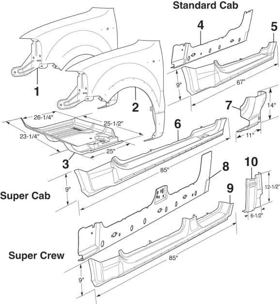
Understanding the variations between different vehicle designs is crucial for anyone working with mechanical layouts. Although many components might serve similar functions across various models, their arrangement, connections, and positioning can differ significantly depending on the manufacturer’s engineering decisions. Comparing these layouts helps identify key differences and allows for better maintenance or customization.
- Layout variations in engine compartments between models
- Changes in wiring connections and harness placements
- Differences in placement of fluid reservoirs or battery locations
Analyzing these variations allows technicians and enthusiasts to adapt their approach based on the specific struc
Tips for Finding Specific Parts
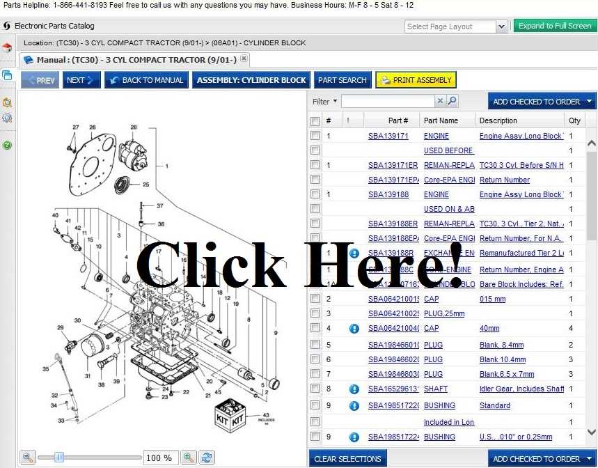
Locating the right components for a vehicle can be challenging, especially if you’re unfamiliar with the details of the system. A strategic approach can save time and ensure you get the correct elements for maintenance or repairs.
- Use reliable online platforms that specialize in automotive supplies. These often offer detailed catalogs that allow you to search by model or type.
- Check compatibility carefully by cross-referencing part numbers. This ensures the item fits your vehicle perfectly without modifications.
- Consult with experts or mechanics if you’re uncertain about the exact component. Their knowledge can guide you toward the right choice, avoiding unnecessary returns.
- Look for reviews or testimonials from other customers. Feedback can reveal t
Utilizing Diagrams for DIY Repairs
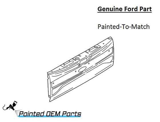
Visual guides are a valuable tool when tackling home repairs, providing a clear overview of the components and how they interact. For those looking to take on repairs themselves, these detailed representations offer insights into the structure and function of various elements, making the process smoother and more efficient.
Below are some key advantages of using such visual tools for do-it-yourself projects:
- Helps identify and understand how components are connected
- Improves accuracy in the disassembly and reassembly process
- Reduces the risk of mistakes by providing a reference throughout the repair
By relying on these resources, anyone can approach repairs with greater confidence and efficiency, ensuring that each step is executed correctly.
Historical Evolution of Ford Diagrams
Throughout automotive history, technical illustrations have played a crucial role in understanding the structure and functionality of vehicles. These visual guides have evolved significantly over the decades, adapting to the growing complexity of modern engineering and the increasing demand for detailed accuracy. Initially simple and straightforward, these illustrations have transformed into intricate blueprints that reflect the advancements in both vehicle design and production techniques.
The progression of these technical sketches mirrors the advancements in the industry itself. Early examples were hand-drawn and focused on the basic mechanical elements, while later versions incorporated more sophisticated features such as electrical systems, safety mechanisms, and advanced technology. With the rise of digital tools, the precision and clarity of these visual aids have reached new heights, making it easier for technicians and enthusiasts alike to navigate complex systems.
The development of these visu
Challenges in Diagram Interpretation
Understanding technical illustrations often presents difficulties for both beginners and experienced individuals. Visual guides can be complex, requiring careful attention to detail and a strong grasp of the underlying systems they represent. Misinterpretations can lead to errors in practical applications, resulting in delays or incorrect solutions.
One common issue is the oversimplification or overcomplication of the visual data, which can confuse the user. Additionally, missing or unclear labels can hinder the process of identifying key elements, making the interpretation process longer and more prone to mistakes.
Another challenge arises from the differences in formatting or representation styles. Not all technical illustrations follow a universal standard, leading to further confusion when users encounter unfamiliar layouts or symbols. The ability to interpret these correctly requires familiarity with various formats and attention to the specific context in which the guide is used.
Future Trends in Diagram Technology
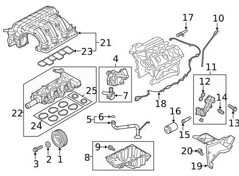
Innovative advancements in visual representation technologies are rapidly transforming the way complex systems are designed and understood. Emerging tools allow for more dynamic, interactive, and real-time visualizations, enhancing accuracy and comprehension in engineering, architecture, and various industries.
One of the most promising directions is the integration of artificial intelligence, enabling predictive modeling and optimization of system structures. Additionally, the rise of augmented reality offers new possibilities for immersive visualization, where users can interact with virtual models in a physical space, improving both design and maintenance processes.
As the technology evolves, we can expect further developments in real-time collaboration platforms, making remote teamwork more seamless and effective. These trends