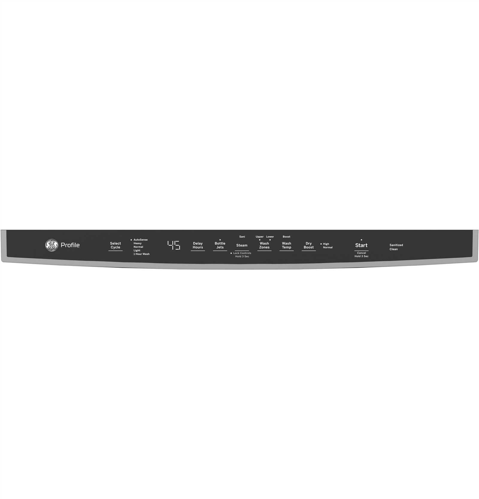
In the realm of complex machinery, comprehending the arrangement of individual elements is crucial for effective maintenance and operation. This exploration delves into the intricacies of how various units are organized within a system, providing insights that enhance user knowledge and efficiency. Recognizing the relationship between different components empowers users to troubleshoot and optimize performance.
Each machine comprises a multitude of distinct segments, each serving a specific function that contributes to the overall operation. By visualizing how these segments interact, one gains a clearer perspective on the mechanics at play. This understanding not only aids in repairs but also fosters a deeper appreciation for the engineering behind the design.
In this discussion, we will highlight the importance of accurately mapping out these configurations. A thorough grasp of the layout can significantly improve the process of diagnosing issues and implementing effective solutions. Ultimately, a detailed representation of how components fit together serves as a valuable resource for anyone looking to enhance their expertise in mechanical systems.
Understanding Pdt715synfs Components
Grasping the elements of complex systems is essential for effective operation and maintenance. Each component plays a vital role, contributing to the overall functionality and performance. By familiarizing ourselves with these parts, we can enhance our understanding and troubleshooting capabilities.
Key Elements
- Core Module
- Interface Unit
- Power Supply
- Control Circuit
- Sensor Components
Functions of Each Component

- Core Module: Acts as the main processing unit, handling computations.
- Interface Unit: Facilitates communication between the user and the system.
- Power Supply: Provides the necessary energy for operation.
- Control Circuit: Manages and directs system operations.
- Sensor Components: Collect data and relay information to the core module.
Key Parts of the Pdt715synfs

This section explores the essential components that contribute to the overall functionality and efficiency of the device. Understanding these elements can help users maintain and troubleshoot effectively.
- Main Assembly: The core structure that houses all components.
- Control Unit: Manages operations and user inputs.
- Power Supply: Provides the necessary energy for operation.
- Connector Interface: Facilitates communication with external devices.
- Cooling System: Maintains optimal temperature during use.
By familiarizing oneself with these critical elements, users can delve deeper into the device’s capabilities and ensure its longevity.
Visual Breakdown of the Parts Diagram
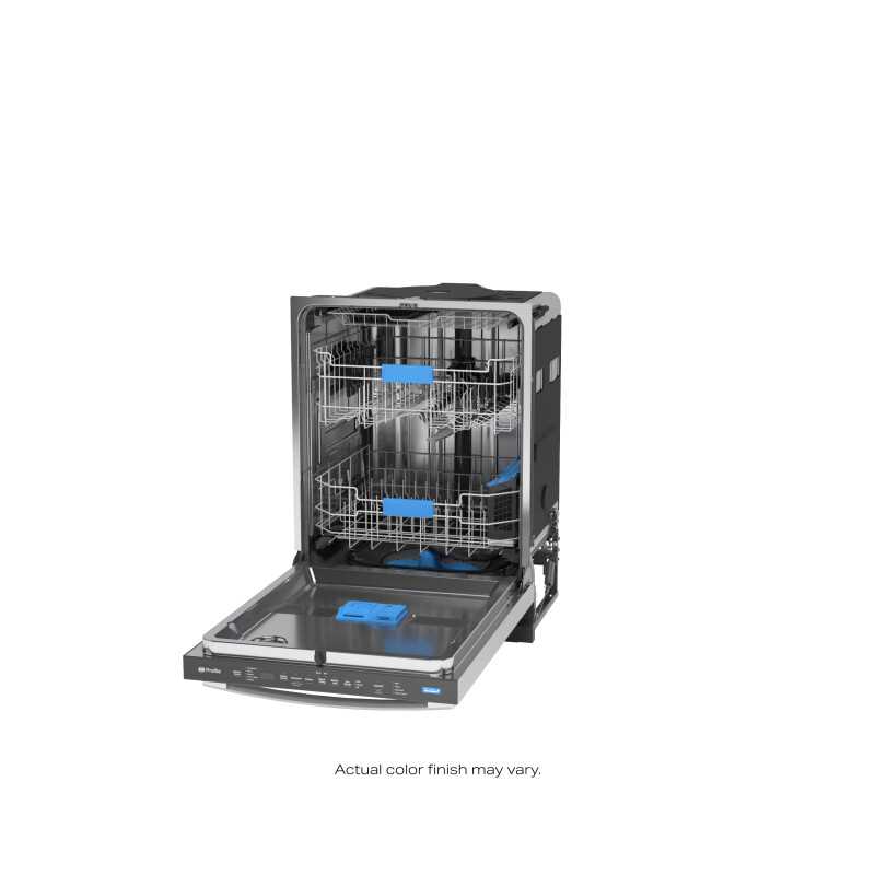
This section provides a detailed exploration of the visual representation that highlights various components within a specific assembly. Understanding the layout and relationships among these elements is crucial for effective maintenance and troubleshooting. The following subsections will outline key features and their significance.
Key Features of the Visual Representation
- Component Identification: Each element is labeled for easy recognition, facilitating quick reference during repairs.
- Color Coding: Different colors may indicate various categories or functions, enhancing clarity.
- Interconnectivity: Lines or arrows often show how parts interact, which is essential for understanding the overall system.
Understanding Relationships and Functions
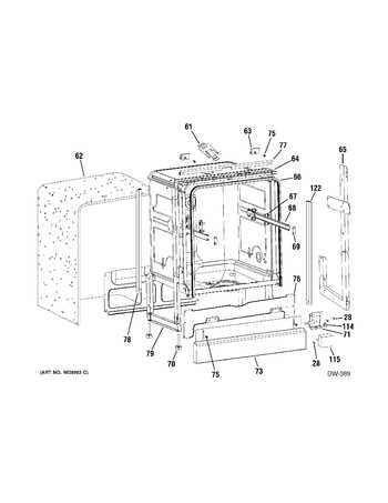
Comprehending how each item fits into the larger context is vital for efficiency. Here are some key considerations:
- Hierarchy: Some components may be primary, while others serve supporting roles.
- Flow: The sequence of operations often dictates how effectively the assembly performs its intended function.
- Maintenance Points: Certain areas may be highlighted to indicate where regular checks or replacements should occur.
Common Issues with Pdt715synfs Parts

When dealing with complex machinery, certain challenges frequently arise that can hinder performance and efficiency. Understanding these common problems can help in identifying potential solutions and ensuring smooth operation.
Frequent Problems Encountered
Users often report a range of malfunctions stemming from wear and tear, improper installation, or incompatibility. These issues can lead to decreased functionality and may require timely intervention to avoid further complications.
Key Symptoms and Solutions
| Symptom | Possible Cause | Recommended Action |
|---|---|---|
| Inconsistent operation | Worn components | Inspect and replace affected items |
| Unusual noises | Improper alignment | Realign and secure components |
| Overheating | Lack of lubrication | Apply appropriate lubricant |
| Excessive vibration | Loose fixtures | Tighten all connections |
By addressing these common issues promptly, users can maintain optimal performance and prolong the lifespan of their machinery.
Replacement Options for Pdt715synfs Components
When seeking alternatives for specific components in machinery, it’s crucial to explore various avenues to ensure optimal performance and reliability. This section will delve into viable options that can be considered when looking to replace essential parts, ultimately providing users with effective solutions.
Aftermarket Alternatives
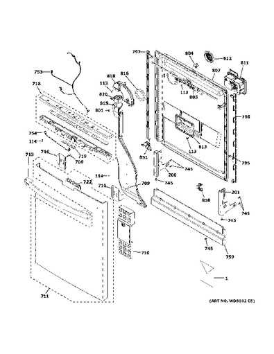
One of the most common approaches is to utilize aftermarket components, which are often designed to meet or exceed original specifications. These replacements can offer significant cost savings while maintaining functionality. However, it’s essential to research the manufacturer’s reputation and warranty options to ensure quality.
OEM Substitutes
Original Equipment Manufacturer (OEM) substitutes provide another reliable choice. These options are typically produced by the same company that manufactured the original parts, guaranteeing compatibility and performance. Although they may come at a premium price, the assurance of quality can be worth the investment for critical applications.
How to Read the Diagram Effectively
Understanding visual representations can enhance your ability to troubleshoot and maintain equipment. By breaking down complex illustrations into manageable sections, you can gain insights into their functionalities and relationships.
To maximize your comprehension, consider the following steps:
- Familiarize Yourself: Spend time looking at the overall layout to understand the structure.
- Identify Key Components: Focus on major elements and their connections.
- Follow Flow Directions: Pay attention to arrows or lines indicating movement or relationships.
- Use Annotations: Make notes on important features or functions as you go.
By applying these strategies, you can delve deeper into the intricacies of the illustration and enhance your overall effectiveness in understanding the system.
Maintenance Tips for Pdt715synfs Parts
Proper care and upkeep of your equipment can significantly enhance its performance and longevity. By adhering to a few straightforward practices, you can ensure that every component operates optimally and is less prone to malfunction.
Regular Inspection
- Conduct frequent visual checks to identify any signs of wear or damage.
- Pay attention to unusual noises or vibrations that may indicate underlying issues.
- Document your findings to track the condition over time.
Cleaning and Lubrication
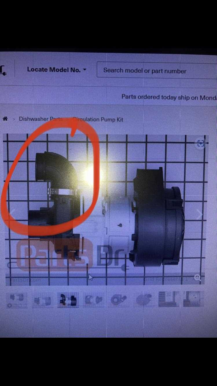
- Keep all surfaces clean to prevent dust and debris buildup.
- Use appropriate cleaning agents suitable for the materials involved.
- Apply lubrication to moving parts to minimize friction and wear.
By implementing these maintenance strategies, you can prolong the lifespan of your equipment and maintain its efficiency. Regular attention to detail will pay off in the long run, ensuring reliable performance.
Tools Required for Parts Replacement
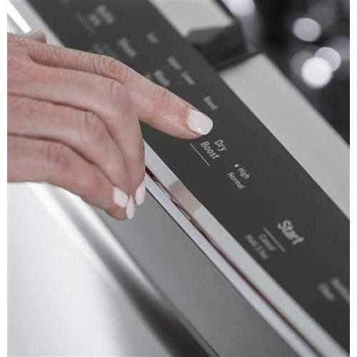
Replacing components in any mechanical system necessitates specific instruments to ensure efficiency and precision. Utilizing the right tools not only streamlines the process but also minimizes the risk of damage to surrounding elements.
Essential Instruments
Key instruments include those designed for gripping, cutting, and securing parts. A well-equipped toolkit should feature both manual and powered options to tackle various challenges.
| Tool | Purpose |
|---|---|
| Wrenches | For loosening or tightening nuts and bolts. |
| Screwdrivers | Essential for fastening and removing screws. |
| Plier Set | Used for gripping and bending materials. |
| Cutter | For cutting through cables or wires. |
| Torque Wrench | Ensures accurate torque specifications. |
Safety Gear
In addition to the primary tools, protective equipment is vital. Proper gear safeguards the user while enhancing the overall safety of the replacement procedure.
Comparative Analysis with Similar Models
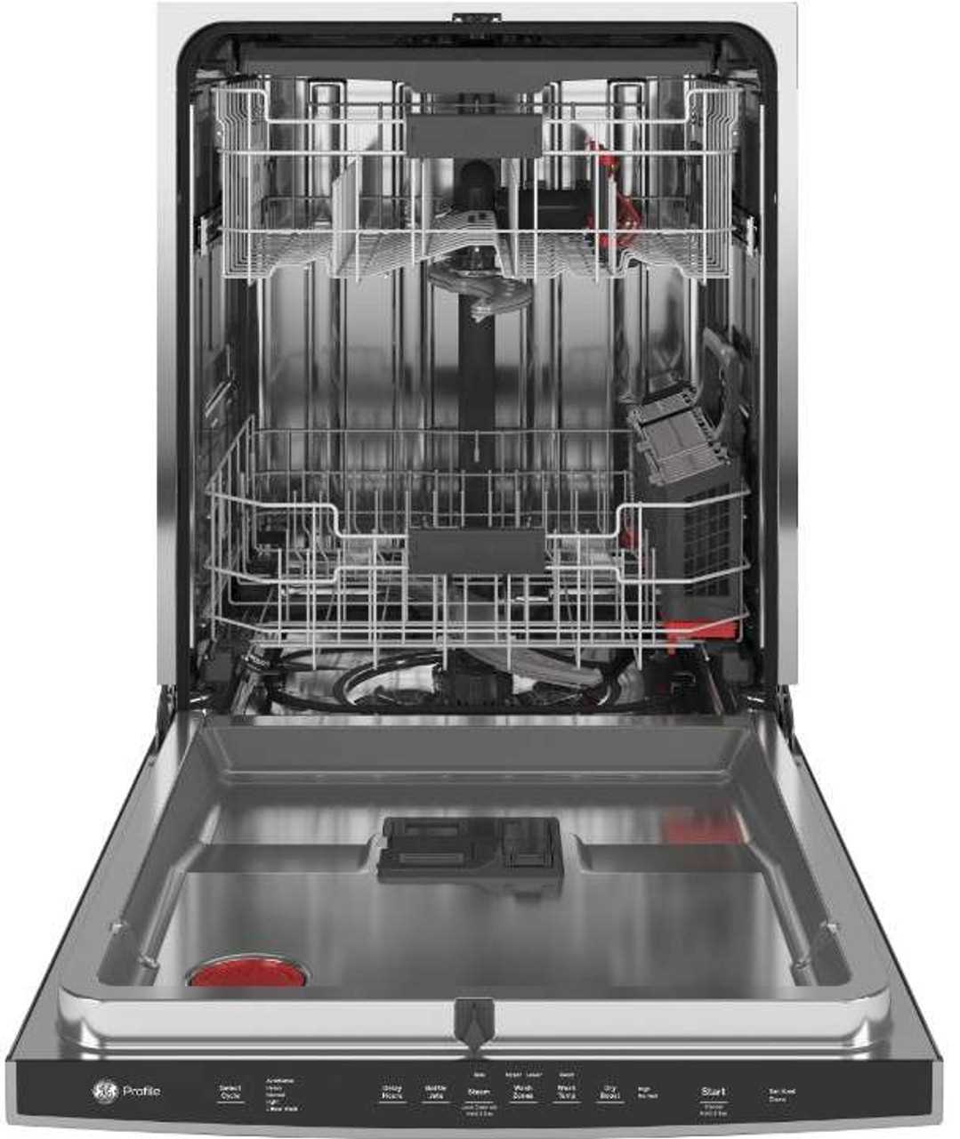
This section explores the characteristics and functionalities of various models that are comparable in design and performance. By examining their features side by side, we can identify strengths and weaknesses that inform potential buyers about their best options.
When considering alternatives, it becomes evident that some models excel in specific areas such as efficiency or user-friendliness, while others might offer superior durability or advanced technology. For instance, certain competitors may provide a more intuitive interface, enhancing the overall user experience, while others focus on robust construction that withstands challenging conditions.
Price points also vary significantly among these alternatives, with some being more budget-friendly, making them attractive for casual users, whereas high-end models may justify their cost with enhanced features and longevity. Ultimately, understanding these differences can aid consumers in making informed decisions that align with their needs and preferences.
Frequently Asked Questions on Parts Diagram
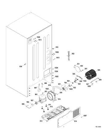
This section addresses common inquiries related to the visual representations used in machinery and equipment. Understanding these illustrations can enhance efficiency and clarity in identifying components and their functions.
What is the purpose of these visual representations?

Visual aids serve as a guide for users, helping to pinpoint various elements within a system. They facilitate maintenance, repairs, and overall comprehension of how different parts interact.
How can I access these illustrations?
Most manufacturers provide downloadable resources on their official websites. Additionally, manuals often contain detailed images that can be referred to when troubleshooting or assembling equipment.