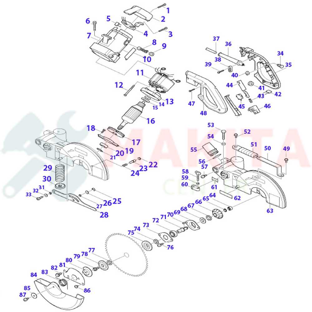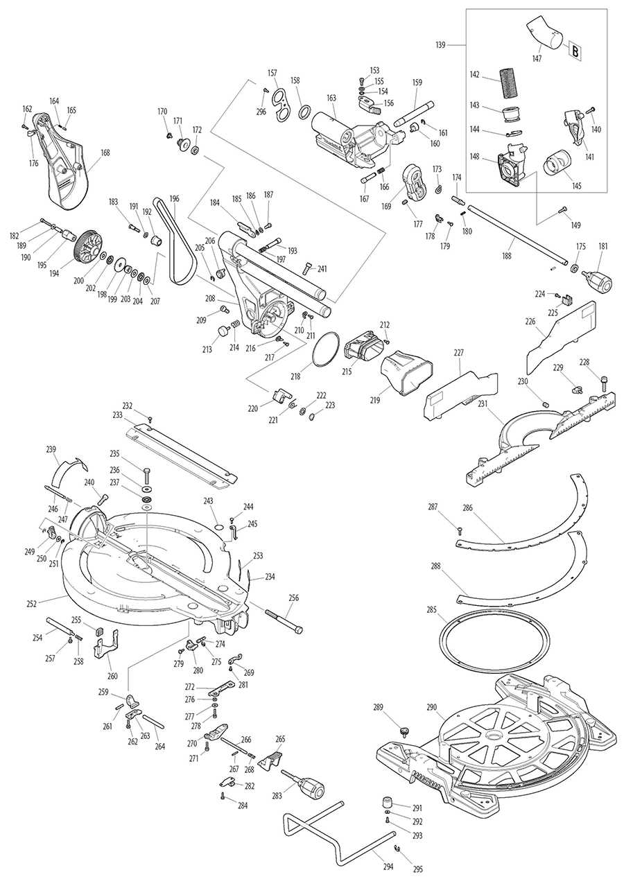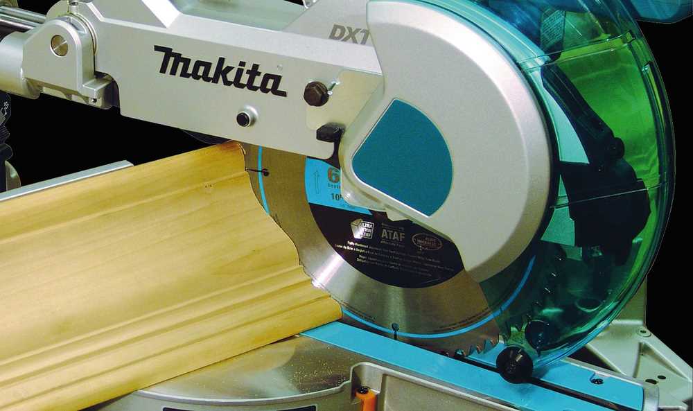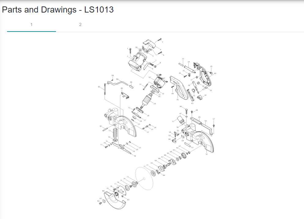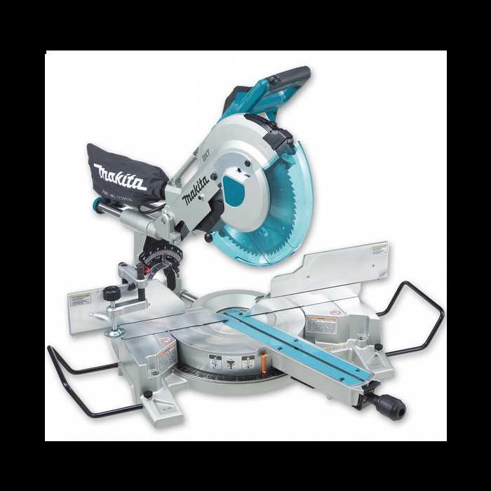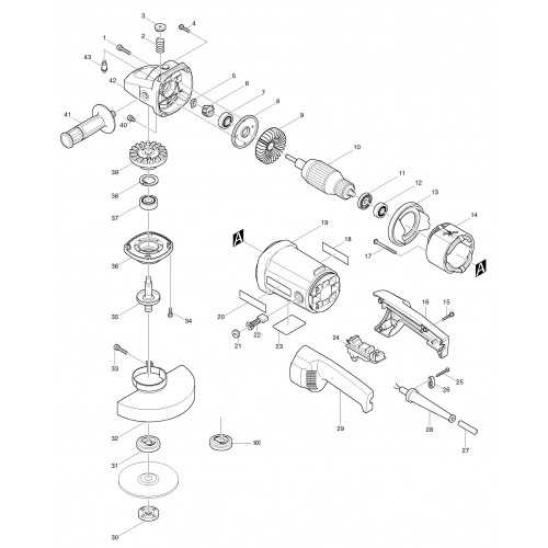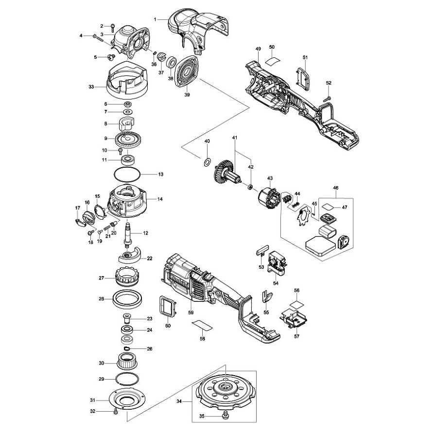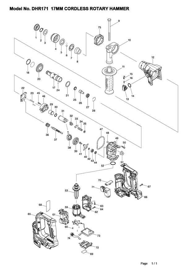
makita ls1013l parts diagram

The internal structure of precision equipment plays a crucial role in ensuring smooth and efficient operation. Understanding how various elements work together can aid in troubleshooting and maintenance, helping to extend the longevity of the tool.

This guide offers a breakdown of the key elements and their interactions within a high-performance device. Knowing the function of each individual element will make it easier to perform necessary adjustments or replacements over time.

Maintaining performance often requires a deeper knowledge of how components are arranged. By exploring each section, you will gain valuable insights into how to maintain optimal functionality and address any potential issues that arise.

Overview of Makita LS1013L Components

This section provides a detailed look into the essential elements of this versatile tool, helping users understand its functionality and assembly. Each component plays a crucial role in ensuring optimal performance and precision in various cutting tasks.

  • Blade Assembly: The central cutting feature, designed for smooth, accurate cuts across different materials.
  • Bevel and Miter Scales: These scales enable the operator to set precise angles, offering flexibility for diverse cutting applications.
  • Fence System: A crucial part that holds materials in place, ensuring stability during operation.
  • Dust Collection Port: This helps maintain a clean workspace by channeling sawdust away from the cutting area.
  • Power Trigger: The control mechanism that powers the tool, providing the operator with full command over the cutting process.

Main Structure of the LS1013L Saw

The structure of this saw model is designed to ensure stability, precision, and durability. Its components are arranged to offer smooth operation while allowing accurate and clean cuts in various materials. Below is a breakdown of the key elements that make up the core framework of the tool.

Base and Support

makita ls1013l parts diagram

The foundation of the saw is a sturdy platform that provides balance and support during use. It is built to handle a range of materials and offers a secure base for cutting operations.

  • Wide base for enhanced stability
  • Adjustable supports to accommodate different workpiece sizes
  • Non-slip surface to prevent material movement

Cutting Mechanism

At the heart of the tool’s design is the cutting mechanism, engineered for precision and control. This section ensures that the saw performs efficiently under various conditions.

  • Rotating blade arm for flexible cutting angles
  • Easy-to-adjust angle settings for miter cuts
  • Locking system to secure the blade in place during operation

Blade Mechanism and Its Parts

makita ls1013l parts diagram

The cutting mechanism plays a crucial role in ensuring the precision and efficiency of the tool. Understanding its components is vital for maintaining smooth operation, safety, and long-term performance. Below, we explore the essential elements that contribute to the functionality of the blade system.

Main Components
makita ls1013l parts diagram

The blade assembly consists of several interconnected elements designed to support accurate cuts. These parts include the rotary blade, the support bracket, and the adjustment knob. Each component must function in unison to provide the best results. Regular inspection and maintenance can prevent damage and prolong their life span.

Adjustment and Safety Features
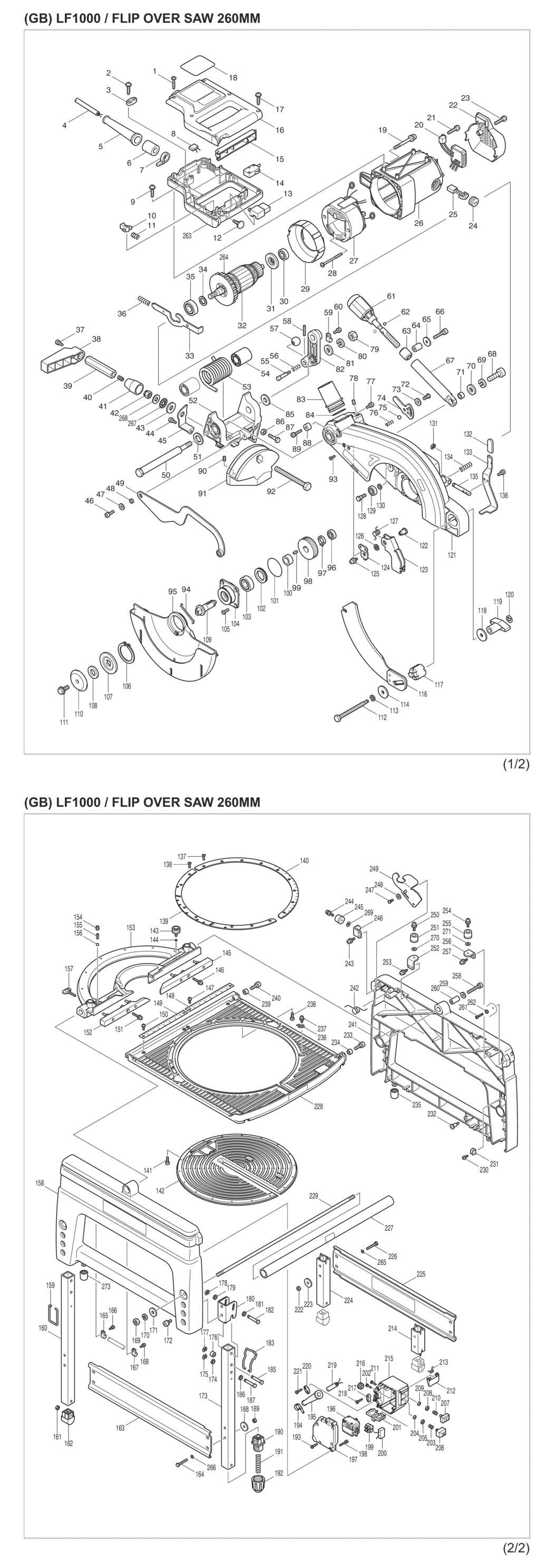
makita ls1013l parts diagram

Proper alignment and safety mechanisms are key to avoiding operational hazards. The blade guard, angle locks, and tension screws ensure that the blade remains stable during use. Each of these features is designed to offer protection while optimizing the tool’s performance.

Handle and Trigger Assembly

makita ls1013l parts diagram

The handle and trigger system is a crucial component for ensuring precise control and comfortable operation of the machine. This section covers the structure, key elements, and functionality of the assembly, focusing on the ergonomic design and efficient trigger response. Proper understanding of this mechanism can improve both the user experience and the longevity of the equipment.

The handle itself is designed to provide a solid grip, ensuring stability and safety during use. The trigger is integrated into the handle, allowing for easy access and smooth activation, reducing operator fatigue. Each element within this assembly is designed for durability and optimal performance in various working conditions.

Fence System and Alignment Parts

makita ls1013l parts diagram

The fence system plays a critical role in ensuring accurate cuts by providing stability and precision. Proper alignment of the fence and other components is essential for maintaining straight and clean cuts, avoiding deviations, and achieving desired results.

Fence Adjustment Mechanism

makita ls1013l parts diagram

Adjusting the fence requires attention to its movement and locking mechanism. Regular checks help ensure the fence stays square to the cutting surface. Over time, realignment may be needed to counter any misalignment caused by wear or external factors.

Precision Alignment Tools

Various tools are available for fine-tuning the fence alignment. These include specialized gauges and measuring instruments that help achieve high precision, ensuring the fence is correctly positioned relative to the blade for optimal performance.

Dust Collection and Hose Connections

Effective removal of debris and dust is crucial for maintaining a clean and safe workspace. Properly managing waste not only enhances visibility but also ensures that tools operate efficiently. A well-designed system for capturing and transporting dust can significantly improve the overall performance of cutting equipment.

Understanding Dust Collection Systems

Implementing an efficient dust collection system involves several key components:

  • Collector: A device that captures particles and dust from the air.
  • Hoses: Flexible tubes that transport dust from the tool to the collector.
  • Adapters: Connectors that allow different tools and hoses to fit together seamlessly.

Connecting Hoses Effectively

To maximize the efficiency of dust collection, follow these best practices for hose connections:

  1. Ensure a tight fit between the hose and the tool to prevent leaks.
  2. Use the appropriate diameter of hose for the specific tool being used.
  3. Regularly check for clogs or blockages in the hose to maintain optimal airflow.
  4. Consider using quick-release connectors for ease of use when switching between tools.

Motor Assembly and Power Components

makita ls1013l parts diagram

The motor assembly serves as the heart of the equipment, playing a crucial role in its overall functionality. Understanding the configuration and integration of power components is essential for efficient operation and maintenance. This section delves into the essential elements that make up the motor and associated power systems, emphasizing their importance in performance and reliability.

Key Elements of the Motor Assembly

The motor assembly consists of various integral parts, including the rotor, stator, and bearings. These components work in unison to convert electrical energy into mechanical motion. Proper alignment and maintenance of these elements are vital for ensuring optimal performance and longevity.

Power Supply Components

Power components, such as capacitors and switches, are essential for regulating and directing the flow of electricity to the motor. Capacitors provide the necessary start-up torque, while switches control the operational state of the device. Understanding the functionality of these parts is crucial for troubleshooting and enhancing the efficiency of the machinery.

Guide Rails and Slide Mechanism

makita ls1013l parts diagram

The effectiveness of a cutting tool largely depends on its supporting structures. These components facilitate smooth and precise operations, allowing for accurate cuts and enhanced control. Understanding the features and functionalities of these elements is essential for optimal performance.

Functionality of Guide Rails

makita ls1013l parts diagram

Guide rails play a critical role in ensuring stability during use. They help maintain alignment and prevent unwanted movement. Key aspects include:

  • Stability: Providing a solid foundation for the cutting process.
  • Precision: Enabling accurate alignment with the material being cut.
  • Durability: Constructed to withstand wear and tear over time.

Understanding the Slide Mechanism

makita ls1013l parts diagram

The slide mechanism complements the guide rails by allowing smooth movement along the cutting path. Its design includes several important features:

  1. Fluid Motion: Facilitating effortless sliding to enhance cutting efficiency.
  2. Adjustability: Allowing for customization based on user preferences.
  3. Maintenance: Simple upkeep ensures longevity and consistent performance.

Safety Features and Switches

The incorporation of safety mechanisms and control switches in power tools is essential for ensuring user protection and preventing accidents during operation. These features are designed to enhance the overall safety and reliability of the equipment, allowing users to work with confidence and peace of mind.

Key Safety Mechanisms

makita ls1013l parts diagram

Various safety mechanisms play a crucial role in preventing unintended activation of the tool. Common features include blade guards, which provide a physical barrier to protect users from accidental contact, and electric brakes that quickly stop the blade’s rotation when the switch is released. These elements contribute to a safer working environment.

Control Switch Functions

The control switches are strategically placed to allow for easy access while minimizing the risk of accidental activation. Typically designed with a locking mechanism, these switches ensure that the tool remains inactive when not in use. Some models also feature variable speed controls, providing users with better management of the tool’s performance according to the task at hand.

Replacement Parts for Common Wear

In any equipment, certain components tend to experience more wear over time due to their frequent use and exposure to various operating conditions. It is crucial to recognize these elements and ensure their timely replacement to maintain optimal performance and prolong the lifespan of the machinery. Understanding which parts are most susceptible to deterioration can help users proactively manage maintenance and avoid unexpected downtime.

The following table outlines common components that may require replacement, along with their typical symptoms of wear and suggested replacement intervals:

Component Function
Rotary Blade
Component Signs of Wear Recommended Replacement Interval
Blade Dullness, chipping, uneven cuts Every 6 months or as needed
Drive Belt Squeaking noise, slippage Annually or as needed
Brushes Reduced power, sparking Every 3-6 months
Switch Intermittent operation, difficulty in starting As needed
Housing Cracks, excessive wear Inspect regularly; replace if damaged

Mounting Hardware and Accessories

Proper mounting elements and supplementary tools play a vital role in ensuring stability and efficiency in various applications. These components are essential for securely attaching equipment and enhancing overall performance.

Essential Mounting Components
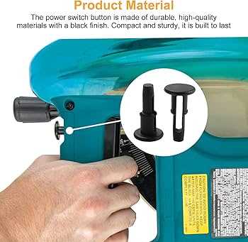
makita ls1013l parts diagram

  • Bolts: Used to connect parts firmly, ensuring a secure fit.
  • Nuts: Paired with bolts to create a strong hold.
  • Washers: Help distribute the load and prevent damage to surfaces.
  • Screws: Useful for fastening items where additional grip is needed.
  • Brackets: Provide support and stability to mounted components.

Additional Accessories
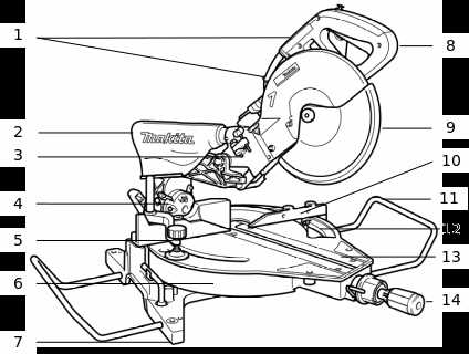
makita ls1013l parts diagram

  1. Safety Guards: Protect users from accidental contact with moving parts.
  2. Extension Cords: Allow for greater flexibility in power supply locations.
  3. Tool Kits: Include various implements for installation and maintenance.
  4. Storage Cases: Keep hardware organized and easily accessible.

Electrical Wiring and Connectors
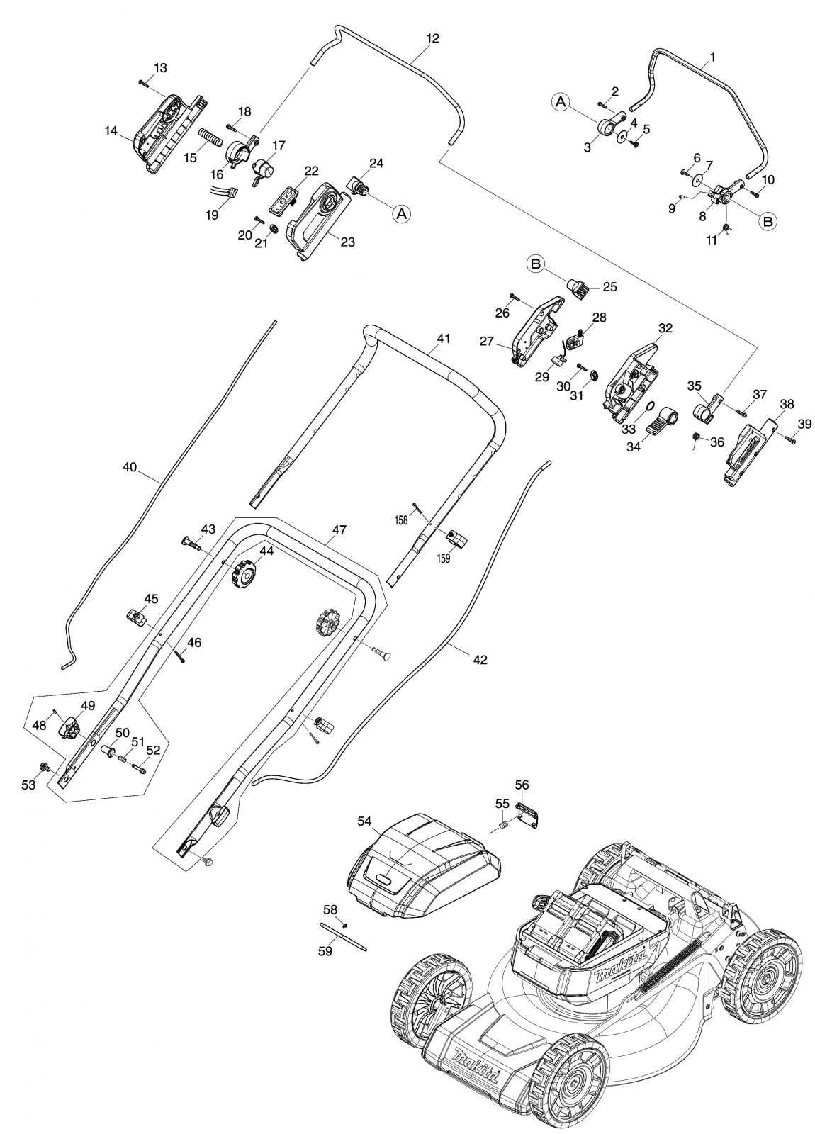
makita ls1013l parts diagram

The effective functioning of power tools relies heavily on the integrity of their electrical systems. This section discusses the various components involved in the electrical wiring of these devices, focusing on the connectors and their roles in ensuring a safe and efficient operation.

Types of Connectors

Connectors are essential for establishing reliable electrical connections. Here are some common types:

  • Terminal Connectors: These are used to connect wires to circuit boards or other components.
  • Splice Connectors: Ideal for joining two wires together, providing a secure and insulated connection.
  • Plug and Socket Connectors: Commonly used for detachable connections, allowing easy disconnection of parts.

Wiring Considerations
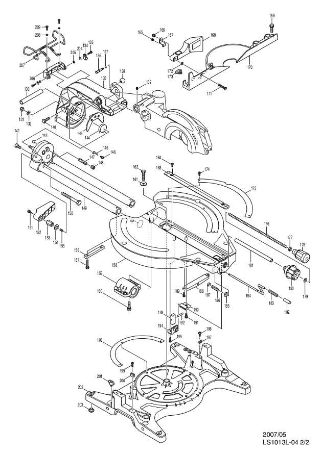
makita ls1013l parts diagram

When dealing with the electrical wiring of power equipment, certain factors should be taken into account:

  1. Wire Gauge: Selecting the appropriate wire gauge is crucial to handle the current without overheating.
  2. Insulation Quality: Ensuring high-quality insulation prevents short circuits and enhances safety.
  3. Connection Security: All connections should be secure to prevent intermittent faults and ensure smooth operation.