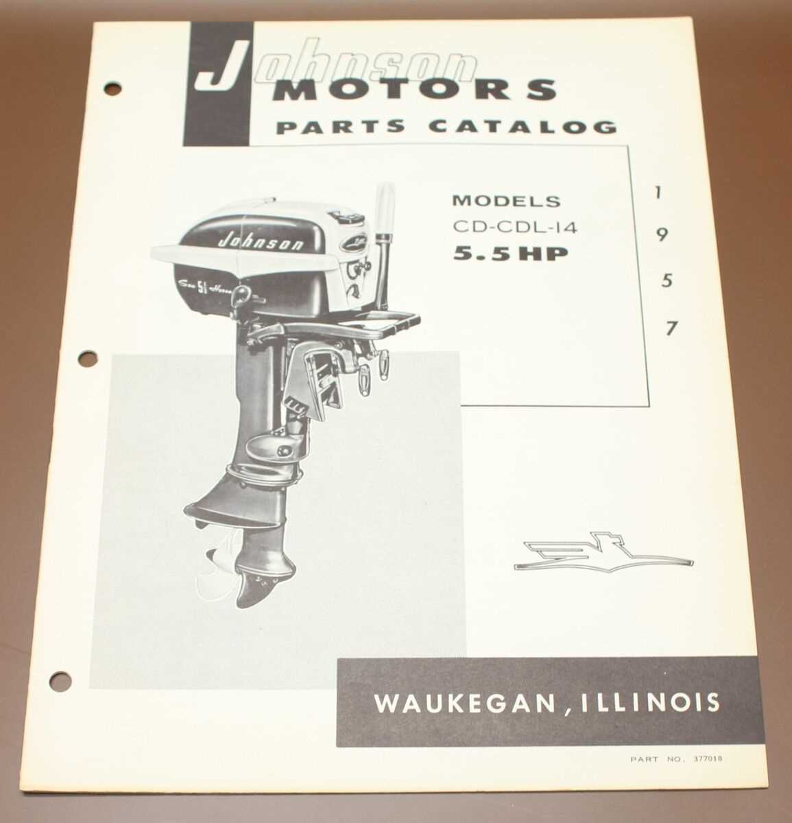
Exploring the inner workings of marine engines can be a fascinating journey. These machines are crafted with precision, ensuring every element functions together seamlessly to power the boat through the water. For those who appreciate the details, knowing how different mechanisms are interconnected and maintained is essential for both enthusiasts and technicians alike.
Older marine engines often come with their own set of unique features and designs that may differ significantly from modern models. Learning how to identify and service the various elements of these engines can be crucial for restoring and maintaining their performance. This knowledge enables the proper handling and replacement of specific components to keep everything running smoothly.
Whether you’re interested in restoring a classic or just want to better understand how the elements of these engines fit together, recognizing the individual sections and their functions can offer valuable insights. With the right resources, it becomes much easier to ensure your marine engine remains efficient and reliable on the water.
1957 Evinrude Parts Diagram Overview
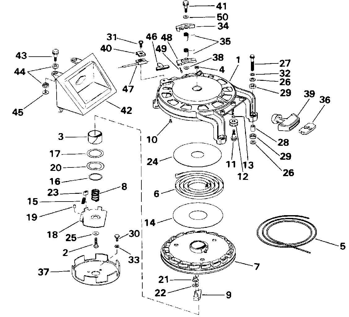
The schematic for this vintage marine engine showcases the intricate arrangement of its components, providing a visual guide to its structure and layout. Understanding how each element fits together can help enthusiasts and mechanics alike grasp the overall mechanics of the engine, making repairs and maintenance more manageable.
Detailed illustrations in the diagram highlight key components, showing their connections and relationships. This helps identify specific sections that may need attention and aids in the proper reassembly of parts during repairs.
By referencing the layout, users can quickly locate and understand the role of different components, which streamlines troubleshooting and ensures a smoother maintenance process.
Identifying Key Engine Components
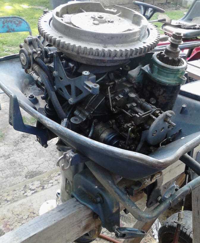
Understanding the primary elements of an engine is crucial for maintenance and repair. Each part plays a specific role, working together to ensure efficient operation. By recognizing the main components, it becomes easier to troubleshoot issues, optimize performance, and extend the engine’s lifespan.
Cylinder block is the foundation, housing essential internal mechanisms. It serves as the framework where various moving parts function, including pistons, which are responsible for converting energy into motion.
The crankshaft is another vital component, transforming linear motion from the pistons into rotational force. This drives the propulsion system, allowing movement to occur smoothly and efficiently.
Fuel delivery relies on a carburetor or fuel injector to mix air and fuel accurately, ensuring proper combustion within the engine’s chambers. Without this, power output and efficiency would significantly diminish.
Ignition
Locating Fuel System Parts
Understanding the structure of the fuel delivery setup can greatly improve maintenance and troubleshooting. This section provides guidance on identifying components that play a crucial role in transporting fuel, ensuring smooth operation and optimal performance.
Key Components to Identify
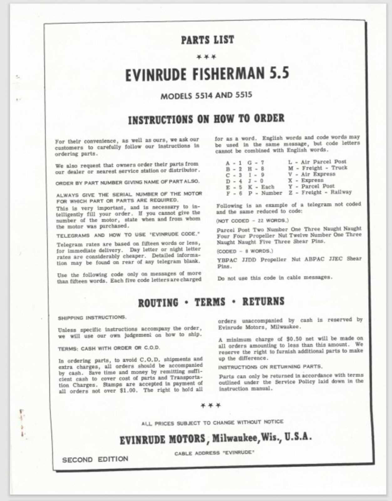
Several elements are involved in the fuel supply chain, each with a specific function. Look for elements such as hoses that connect the tank to the engine, filters that keep contaminants out, and the carburetor responsible for mixing air and fuel. Locating these elements can help pinpoint potential issues affecting the motor’s efficiency.
Inspecting Common Problem Areas
When searching for possible issues, start by checking for leaks or blockages in the supply lines. Connections between hoses and fittings should be tight, and any signs of wear or damage might indicate the need for replacement. Proper inspection o
Understanding the Ignition Assembly
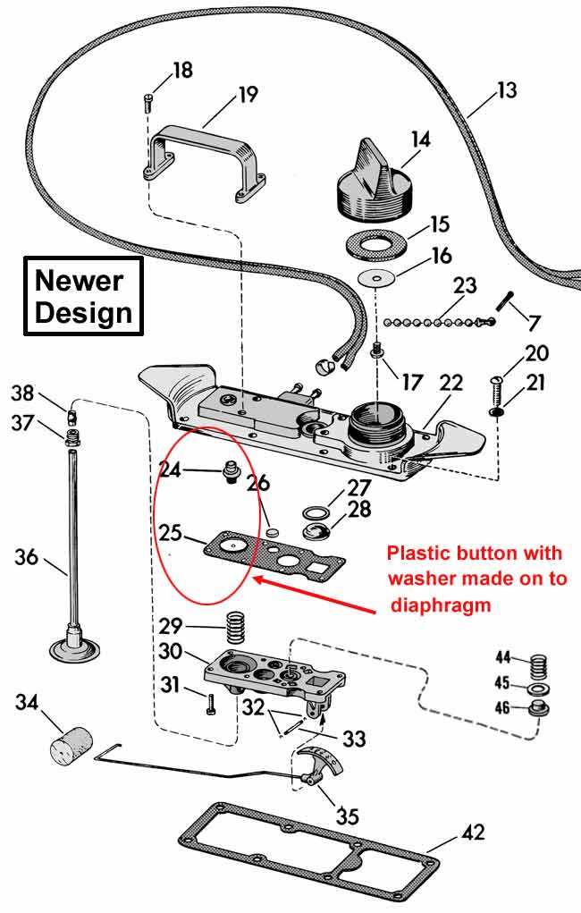
The ignition assembly is a crucial component that ensures the smooth starting and operation of an engine. Its primary function is to generate the necessary electrical spark to ignite the fuel mixture, driving the engine’s internal combustion process. The assembly consists of several interconnected parts that work in harmony to create a consistent spark, enabling reliable engine performance.
Key elements within the ignition system include components responsible for voltage generation, timing mechanisms, and connections that deliver the spark to the engine. Each part must be in optimal condition, as even minor issues can significantly affect the overall functionality of the ignition process. Regular maintenance and inspection help ensure these components continue to function efficiently.
Understanding how these elements interact can aid in troubleshooting and identifying potential issues within the system. Familiarity with the assembly’s structure and common problem areas can also enhance the ability to maintain and repair the ignition system effectively.
Examining the Cooling System Layout
The cooling system plays a crucial role in maintaining optimal engine performance by regulating temperature and preventing overheating. Understanding the design and flow of this system is essential for ensuring reliable operation, as well as for troubleshooting potential issues that may arise. A well-functioning cooling arrangement helps to extend the lifespan of the engine and avoid serious damage caused by excessive heat.
Key Components and Their Functions
The cooling system typically includes a water pump, thermostats, hoses, and a network of passages designed to facilitate heat exchange. The water pump circulates coolant through the engine, absorbing heat from the internal components. Thermostats help regulate the flow, allowing the engine to reach and maintain the ideal temperature range. Hoses connect these components, guiding the coolant along its path while ensuring efficient heat transfer throughout the system.
Flow Path and Heat Exchange Process
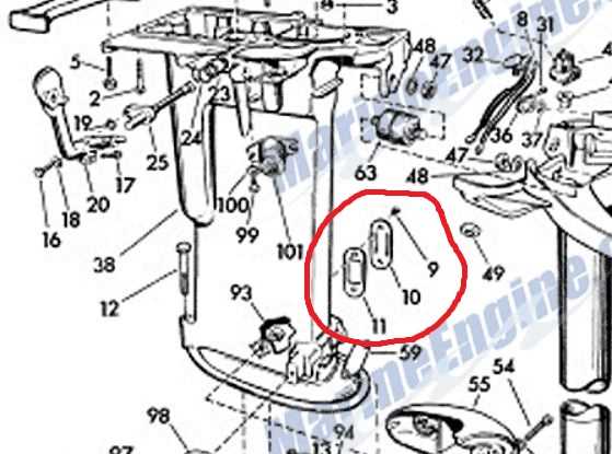
The coolant flow begins at the pump, moving through channels that direct it toward critical areas. As the coolant absorbs heat, it exits through an outlet to be discharged or recirculated, depending on the system’s configuration. The heat exchange process is vital for maintaining engine stability, allowing continuous operation without the risk of overheating.
Interpreting the Throttle Linkage Setup
Understanding the configuration of the throttle linkage is crucial for optimal engine performance. This assembly plays a vital role in controlling the power output of the motor, allowing for smooth acceleration and deceleration. Proper interpretation of this setup ensures effective communication between the throttle and the engine, facilitating responsive handling.
To effectively assess the throttle linkage, consider the following components:
- Rod Linkages: These connect various parts and enable movement.
- Adjustment Mechanisms: These allow for fine-tuning the throttle response.
- Pivot Points: These are crucial for the rotation of the linkage and must be well-lubricated.
Here are key steps to analyze the throttle linkage:
- Inspect the entire assembly for wear and damage.
- Check the alignment of the rod linkages to ensure smooth operation.
- Test the adjustment mechanisms to confirm they are functioning correctly.
By systematically evaluating these aspects, one can maintain the efficiency and reliability of the throttle system, ensuring a seamless boating experience.
Exploring Gearcase Assembly Details
The gearcase assembly is a vital component of any marine propulsion system, responsible for transferring power from the engine to the propeller. Understanding its intricacies can enhance maintenance practices and improve overall performance. By delving into its structure, one can appreciate the engineering that ensures durability and efficiency in various water conditions.
Key Components of the Gearcase
At the heart of the gearcase assembly lies a series of interconnected parts, each serving a specific function. The drive shaft plays a crucial role in transmitting rotational energy, while the gear set allows for speed adjustments and torque management. Additionally, seals and bearings are essential for maintaining proper lubrication and preventing leakage, which is vital for the longevity of the assembly.
Maintenance Considerations
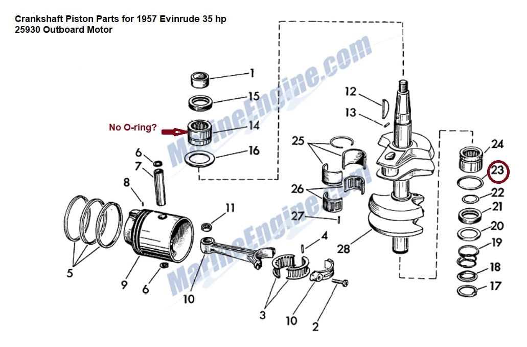
Regular inspections and maintenance of the gearcase can prevent potential failures and enhance the lifespan of the entire assembly. Attention should be given to the condition of the seals and bearings, as well as the gear set’s integrity. Ensuring that these components are in optimal condition not only improves performance but also contributes to safe and enjoyable boating experiences.
Deciphering the Exhaust System Configuration
The configuration of the exhaust system plays a crucial role in the overall performance and efficiency of any watercraft. Understanding its components and their arrangement is essential for optimal operation. This section will explore the intricate aspects of the exhaust setup, highlighting key elements and their functions, thereby assisting enthusiasts and technicians in navigating the system effectively.
Key Components of the Exhaust System
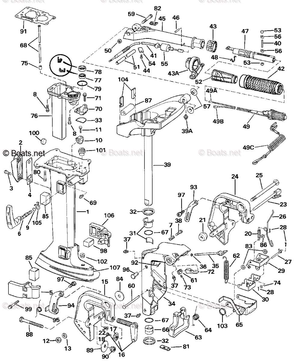
At the heart of the exhaust setup are various elements that work together to facilitate the expulsion of gases. Each part serves a distinct purpose, contributing to the effective operation of the vessel. Below is a brief overview of the primary components:
| Component | Function |
|---|---|
| Exhaust Manifold | Collects exhaust gases from the engine cylinders |
| Silencer | Reduces noise generated during operation |
| Tail Pipe | Directs exhaust away from the vessel |
| Water Injection System | Cools exhaust gases to prevent overheating |
Understanding System Layout
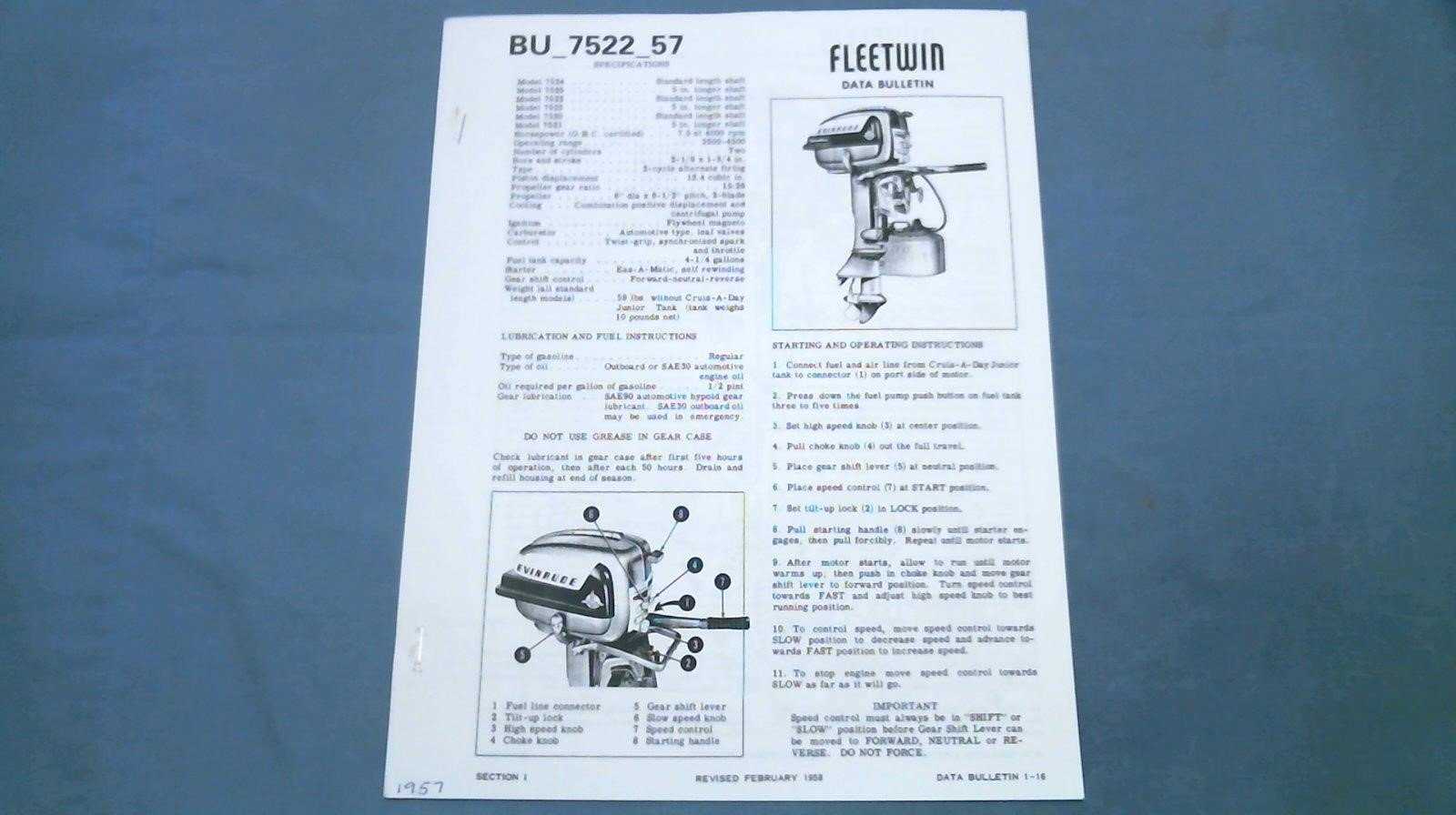
Analyzing the arrangement of these components provides insights into how the system functions as a whole. The layout not only influences performance but also affects maintenance routines. A well-designed exhaust configuration ensures that gases exit smoothly, reducing backpressure and enhancing efficiency.
Inspecting the Electrical Wiring Schematic
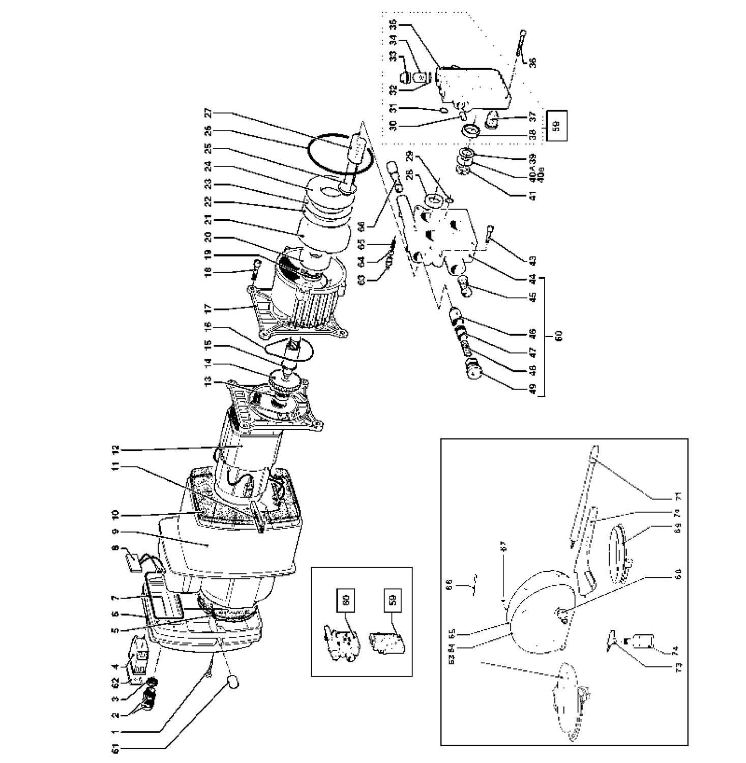
Understanding the electrical system of a watercraft is crucial for ensuring its optimal performance and safety. By thoroughly examining the wiring layout, one can identify potential issues that may disrupt functionality. This process involves reviewing the connections, assessing the condition of the components, and ensuring proper grounding.
Reviewing Connection Points
Begin by checking all connection points for signs of wear or corrosion. Corroded terminals can lead to poor conductivity, causing electrical failures. Ensure that each wire is securely attached and that there are no loose connections that could result in intermittent power loss.
Evaluating Component Integrity
Next, focus on the integrity of the electrical components. Look for any frayed wires or damaged insulation that could pose a risk of short circuits. Replacing any compromised elements is essential to maintain a safe and reliable electrical system.
Reviewing Propeller Shaft Components
The propeller shaft is a crucial element in the mechanics of marine propulsion systems, playing an integral role in transmitting power from the engine to the propeller. Understanding its various components can enhance maintenance practices and improve overall performance. This section delves into the key parts associated with the propeller shaft, offering insights into their functions and importance.
One of the primary components is the shaft itself, which serves as the main conduit for transferring rotational energy. Its design and material greatly influence durability and efficiency. Alongside the shaft, bearings provide support and allow smooth rotation, minimizing friction and wear over time. Choosing high-quality bearings is essential for maintaining optimal performance.
Additionally, seals are vital in preventing water ingress, thereby protecting internal mechanisms from corrosion and damage. Regular inspection and replacement of seals can significantly extend the lifespan of the propulsion system. Furthermore, the coupling connects the shaft to the engine, ensuring a secure and reliable link between components.
In summary, a thorough understanding of these components not only facilitates better upkeep but also enhances the efficiency and reliability of the marine vessel. Proper care and timely replacements are key to ensuring a seamless operation of the propulsion system.
Maintenance Tips for Diagram Accuracy
Ensuring the precision of technical illustrations is essential for effective repairs and servicing. A well-maintained visual guide not only aids in identifying components but also enhances overall understanding. Here are some strategies to maintain the reliability of your schematics.
- Regular Inspection: Frequently review the visual aids for any signs of wear or deterioration. Make note of any faded areas or unclear sections that could hinder understanding.
- Use Quality Materials: When printing or reproducing guides, utilize high-quality paper and ink to prevent smudging and fading over time.
- Digital Backups: Keep digital copies of your illustrations in multiple formats. This practice ensures you have access to clear images even if physical copies deteriorate.
- Update with New Information: As repairs and services evolve, ensure that your visual guides reflect the latest data and modifications. Incorporate any changes promptly to maintain accuracy.
- Organize Properly: Store your diagrams in a systematic manner. Use binders or folders to protect them from dust and damage, and label them for easy retrieval.
By implementing these practices, you can significantly enhance the reliability of your technical illustrations, making maintenance tasks smoother and more efficient.