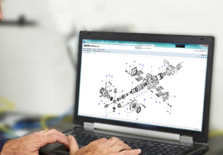
Understanding the structure and organization of mechanical systems can be crucial for maintaining and repairing equipment efficiently. A visual representation of these systems allows for a clearer perspective on how various elements fit together. Such resources are indispensable when performing maintenance or troubleshooting issues.
In this section, you will find an in-depth look at the layout of individual components, providing a comprehensive guide to understanding the key connections within the system. Whether it’s for regular upkeep or specific repairs, having a clear overview can make all the difference in ensuring the longevity and optimal performance of your machinery.
Clear visuals and well-organized information offer a step-by-step insight, simplifying the process of identifying and working with various elements within the system. This approach ensures that users can approach tasks with confidence and precision.
Understanding AGCO Components Layout
In any machinery, the proper arrangement of its mechanical elements is essential for optimal functionality. Knowing how different sections and units are positioned and connected helps with maintenance, repairs, and overall understanding of how the equipment operates.
Key Structural Elements
The main structural pieces are organized logically, allowing for efficient performance. Each element has a specific role, contributing to the overall system’s efficiency. Identifying these core parts and their location enhances the ability to work with the machinery effectively.
Efficient System Organization
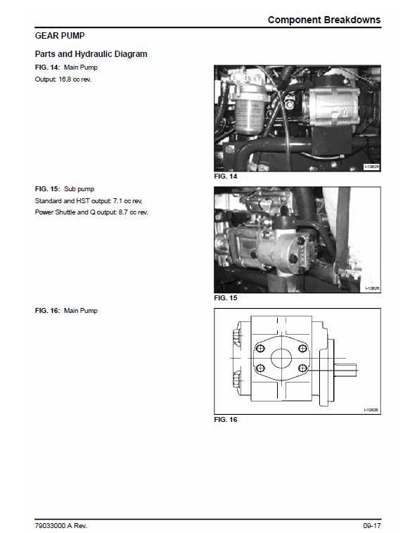
Proper organization of the equipment’s individual sections ensures smooth operation. From the engine assembly to the hydraulic systems, everything is aligned to maximize output and reduce the need for frequent adjustments or servicing.
How to Navigate the AGCO Parts System
Efficiently navigating a platform designed for equipment components can streamline maintenance and ensure timely repairs. Understanding the structure and tools available in such a system is essential for accessing necessary items quickly.
Key Interface Features
The user interface provides several functionalities that simplify the search process. By using search filters and categories, you can narrow down the results to specific models or assemblies, ensuring precision in your selections. Familiarizing yourself with these options will help reduce the time spent browsing.
Using Search Tools
A variety of search methods are available, from entering serial numbers to exploring pre-defined categories. Whether you are looking for a specific element or browsing through an entire assembly, the system allows you to efficiently find the right components.
| Function |
|---|
| Feature | Description | |||||||||||||||||||||||||||||||||||||||||||
|---|---|---|---|---|---|---|---|---|---|---|---|---|---|---|---|---|---|---|---|---|---|---|---|---|---|---|---|---|---|---|---|---|---|---|---|---|---|---|---|---|---|---|---|---|
| Detailed Visualization | Offers a comprehensive display of each component and its connections. | |||||||||||||||||||||||||||||||||||||||||||
| User-Friendly Interface | Ensures easy navigation through different sections and components. | |||||||||||||||||||||||||||||||||||||||||||
| Efficient Search Functions | Allows users to quickly find specific elements within the system. |
| Component | Function | Maintenance Frequency | ||||||||||||||||||||||||||||||||||
|---|---|---|---|---|---|---|---|---|---|---|---|---|---|---|---|---|---|---|---|---|---|---|---|---|---|---|---|---|---|---|---|---|---|---|---|---|
| Engine System | Powers the machine | Monthly | ||||||||||||||||||||||||||||||||||
| Hydraulic Unit | Controls lifting mechanisms | Bi-Annually |
| Feature | Brand A | Brand B | Brand C |
|---|---|---|---|
| Clarity | High | Medium | Low |
| Detail Level | Comprehensive | Moderate | Simplified |
| User-Friendliness | Excellent | Good | Poor |
Interpreting Visual Layouts for Efficient Repairs
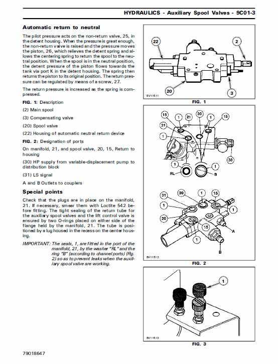
Understanding visual representations is crucial for performing effective maintenance and troubleshooting. These layouts serve as guides, helping technicians identify components and their relationships within a system. By mastering the interpretation of these diagrams, repair professionals can streamline their processes and minimize downtime.
Key Elements to Focus On
- Symbols and Legends: Familiarize yourself with the common symbols used in visual layouts, as they denote specific parts and functions.
- Connections: Pay attention to how components are interconnected, which can provide insights into the flow of operations.
- Color Coding: Utilize color cues that often indicate the status or type of each component, aiding in quick assessments.
Steps for Effective Interpretation

- Start by examining the overall layout to grasp the general structure.
- Identify the main components and their respective functions.
- Trace connections to understand how each part interacts with others.
- Use the legend to clarify any unfamiliar symbols.
By honing your skills in interpreting these layouts, you can enhance your efficiency in repairs and ensure that systems operate smoothly.
AGCO Diagram Updates: What to Know
Staying informed about the latest enhancements and modifications in component schematics is crucial for effective maintenance and repair of machinery. Understanding these updates allows operators and technicians to optimize their workflows and ensure the longevity of their equipment.
Recent revisions in schematics include:
- Improved Clarity: New layouts provide clearer visual representations, making it easier to identify components.
- Detailed Annotations: Enhanced descriptions accompany each element, offering better guidance during repairs.
- Incorporation of New Components: The latest versions include newly developed parts, reflecting advancements in technology.
To make the most of these updates, users are encouraged to:
- Regularly check for the latest versions of schematics.
- Familiarize themselves with changes to avoid confusion during repairs.
- Utilize updated resources to enhance understanding of machinery functionality.
Tips for Reading Agricultural Machinery Diagrams
Understanding visual representations of machinery components can greatly enhance your ability to maintain and repair equipment. These illustrations often convey crucial information about assembly and functionality, making them essential for effective troubleshooting and parts identification.
Familiarize Yourself with Symbols
Most technical drawings use specific symbols to represent various parts and functions. Taking the time to learn these icons will allow you to quickly identify components and their relationships. Here are some common symbols you might encounter:
| Symbol | Description |
|---|---|
| ⚙️ | Gear |
| Bolt | |
| Tool | |
| ️ | Maintenance |
Break Down the Information
Rather than trying to interpret the entire illustration at once, focus on smaller sections. Start with one component and analyze its connections and functions within the whole system. This methodical approach helps in grasping complex layouts and ensures a thorough understanding of each part’s role.
Exploring AGCO’s Online Diagram Tools
The digital landscape offers an array of resources for users seeking to enhance their understanding of equipment components. One prominent feature in this realm is the availability of interactive visual aids that facilitate easy navigation through various assemblies and elements. These online resources are designed to assist users in identifying essential components, ensuring smooth maintenance and efficient operations.
Benefits of Interactive Visual Aids
Utilizing these digital tools presents several advantages for both professionals and enthusiasts. Users can conveniently access detailed visual representations, enabling quick identification and understanding of intricate systems. Moreover, these resources often provide additional information, such as specifications and compatibility, enhancing the overall user experience.
Navigating the Resources
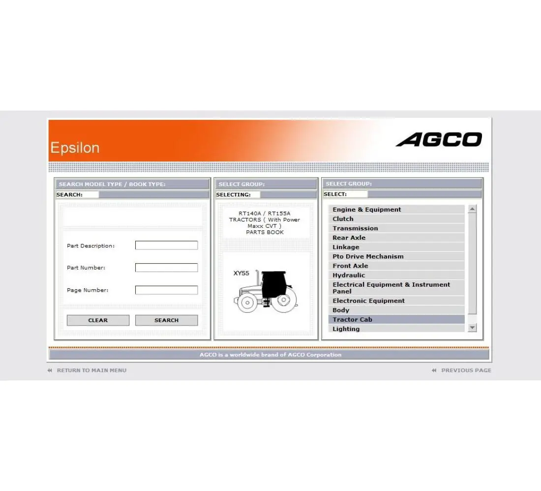
To effectively utilize these online tools, users can follow a straightforward approach. The primary steps involve selecting the desired equipment category, locating the relevant visual guide, and exploring the different elements within the assembly. This process not only simplifies the task at hand but also empowers users to gain deeper insights into their machinery.
| Feature | Description |
|---|---|
| Interactive Navigation | Allows users to click on components for detailed information. |
| Compatibility Data | Provides insights into which parts work together seamlessly. |
| User-Friendly Interface | Designed for easy access and intuitive use, catering to all skill levels. |
