In this section, we explore the detailed layout of key elements within specialized snow-handling machinery. Understanding how different elements are organized and connected is essential for effective maintenance and troubleshooting. By delving into the structure, we provide insights that will help ensure optimal functionality and ease of service.
Each element in the equipment works in coordination with others, forming a cohesive system. Knowing the placement and relationship between these elements can significantly simplify repairs, replacements, and overall upkeep. This guide is designed to offer a clear view of how various components interact within the system, making it easier for users to maintain peak performance during operation.
Understanding the Curtis Sno-Pro 3000 System
Snowplow systems rely on intricate mechanical and hydraulic components to ensure optimal snow removal. By comprehending how each element interacts, you can maintain and enhance the system’s performance, ensuring long-lasting durability and reliability.
| Component | Function | ||||||||||||||||||||||||
|---|---|---|---|---|---|---|---|---|---|---|---|---|---|---|---|---|---|---|---|---|---|---|---|---|---|
| Hydraulic Pump | Controls the movement of the blade, allowing precise adjustment for snow removal. | ||||||||||||||||||||||||
| Control Unit | Offers the operator full command over the plow’s various functions, including lifting and angling. | ||||||||||||||||||||||||
| Mounting Frame | Attaches the
Main Components of the Curtis Sno-Pro 3000The equipment for effective snow control consists of several key elements, each contributing to its reliable operation and performance. These elements ensure that the machine can handle various weather conditions and road surfaces, delivering the precision and durability required for heavy-duty tasks. In this section, we’ll explore the most critical components that play a central role in the functionality of the snow-clearing machine. Blade SystemThe primary feature is the blade system, responsible for moving large amounts of snow efficiently. It consists of a high-strength steel cutting edge that can withstand extreme conditions. The blade’s angle and adjustability make it a versatile tool for different snow depths and surface types Identifying Key Parts for MaintenanceUnderstanding the essential components of your equipment is crucial for ensuring smooth operation and timely upkeep. By familiarizing yourself with these elements, you can easily recognize when servicing or replacement is necessary, thus preventing breakdowns and extending the overall lifespan of your machinery. Main Components to Focus OnStart by examining the primary mechanisms that drive the performance of the system. Pay close attention to items that experience the most wear and tear, such as the hydraulic controls, electrical connections, and mechanical joints. These are the areas where regular inspections can help detect early signs of fatigue or damage. Connections and Moving ElementsThe next area to inspect involves the various connectors and moving parts within the system. This includes checking bolts, pivots, and linkages for any signs of looseness Assembly Layout for the Sno-Pro 3000
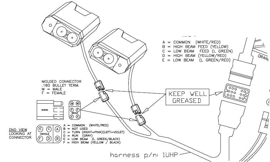
The structural arrangement of the snowplow system is crucial for ensuring smooth operation and durability in harsh conditions. Understanding how various elements come together can help with both installation and maintenance, allowing users to maximize efficiency and avoid unnecessary breakdowns. Below is a detailed overview of how the key components are organized within the system. Main Frame StructureThe main framework provides the core support for the entire setup. It consists of reinforced steel bars designed to handle heavy loads and repeated use in winter environments. The frame connects securely to the vehicle, distributing the weight evenly while also housing essential mechanical elements like hydraulic pistons and mounting brackets. Hydraulic and Electrical ComponentsThe hydraulic system is responsible for controlling the lifting, angling, and lowering actions. It is integrated with several hoses, pumps, and actuators, all strategically placed within the framework for easy access and optimal performance. In addition, the electrical wiring, including the control Hydraulic System Overview and FunctionsThe hydraulic system plays a crucial role in ensuring efficient operation by transmitting power through pressurized fluid. Its design allows for precise control over various components, enabling smooth performance of mechanical tasks. Understanding the functionality of the hydraulic components is essential to maintaining optimal efficiency and reliability. Key Components of the Hydraulic SystemA typical hydraulic system consists of several key elements. These include a pump, which generates the necessary pressure, valves that control the direction and flow of the fluid, and cylinders, which convert the hydraulic energy into mechanical force. Each of these parts works in unison to deliver the required output. Functions and BenefitsThe primary function of the hydraulic system is to provide powerful Wiring Diagram for Efficient OperationCreating an effective wiring scheme is crucial for the optimal functionality of any machinery. Proper connections ensure that all components operate harmoniously, reducing the risk of malfunction and enhancing overall performance. In this section, we will explore the essential elements of an effective wiring layout that promotes efficiency. Key Components to Consider
Steps for Creating an Effective Wiring Layout
Blade Adjustment Mechanism and SetupThe adjustment system for the cutting edge is a crucial component that influences the efficiency and performance of snow management equipment. This mechanism allows operators to fine-tune the height and angle of the blade, ensuring optimal ground contact and material handling. Proper setup can enhance maneuverability and effectiveness in various snow conditions. Understanding the Adjustment ComponentsThe mechanism consists of several key elements that work together to facilitate smooth adjustments. These components include adjustable brackets, tension springs, and a lever system. Understanding how each part functions is essential for effective setup and maintenance.
Setting Up the Adjustment MechanismTo achieve the best performance, it is important to follow a systematic approach when setting up the adjustment mechanism. First, ensure all components are in good condition and properly lubricated. Next, determine the desired height for the cutting edge based on the specific application. Finally, use the lever system to make precise adjustments, checking the blade’s angle and contact with the ground as you proceed. Hydraulic Pump Components and DetailsThe hydraulic pump is a crucial mechanism in various machinery, designed to convert mechanical energy into hydraulic energy. This process enables the efficient transmission of power, allowing for a wide range of applications in different sectors. Understanding the individual elements of the pump helps in optimizing its performance and maintenance. Main ComponentsThe core components of a hydraulic pump typically include the following:
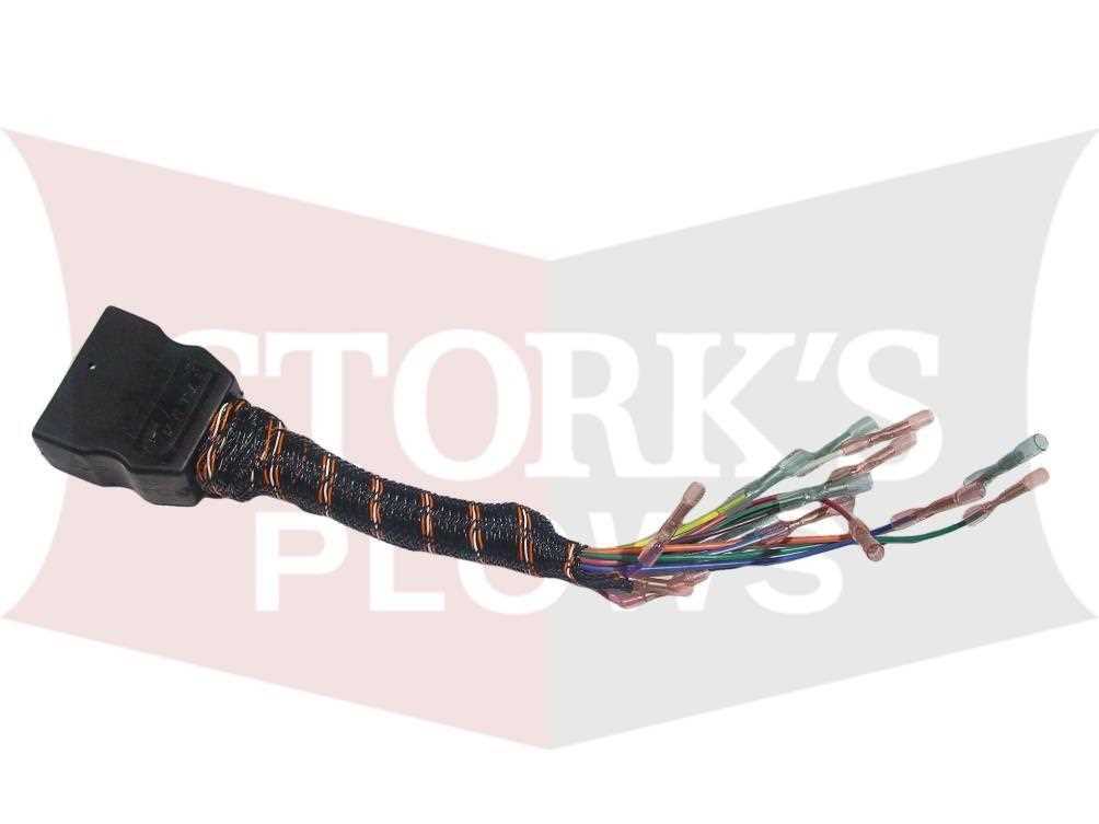
Functionality OverviewThe functionality of the hydraulic pump relies on the interplay between its components. The drive shaft initiates the rotation of the gearset, which in turn draws hydraulic fluid into the housing. As the gears mesh, they compress the fluid and push it towards the outlet port, creating the necessary pressure for system operation. Regular inspection of these elements is essential for ensuring longevity and optimal functionality. Controller Unit: Functions and ConnectionsThe controller unit serves as a vital component in electric drive systems, facilitating communication between various parts of the machinery. Its primary role is to manage the performance and efficiency of the electric motor, ensuring optimal operation under varying conditions. Understanding its functions and connections is crucial for troubleshooting and maintenance. Key Functions
Connection PointsProper connections are essential for the effective functioning of the controller unit. The following points are typically found:
By comprehensively understanding these functions and connection points, operators can ensure the system runs efficiently and reliably, leading to enhanced performance and reduced downtime. Replacing Wear Parts for Optimal PerformanceMaintaining equipment in top condition is crucial for achieving peak efficiency and longevity. Over time, specific components can experience wear due to regular use, impacting the overall functionality of the system. Timely replacement of these elements is essential to ensure seamless operation and prevent further damage. Identifying Worn ComponentsRecognizing when to replace specific elements can significantly enhance performance. Here are common indicators of wear:
Replacement ProcessFollowing a systematic approach for replacing worn components is vital. Consider these steps:
By routinely assessing and replacing worn components, you can maximize the efficiency and lifespan of your equipment. Electrical Connections and TroubleshootingThis section focuses on understanding the electrical linkages within snow removal equipment and provides guidance on identifying and resolving common issues. Proper electrical connectivity is crucial for ensuring optimal functionality and performance of the equipment. Begin by inspecting all wiring for signs of damage, wear, or corrosion. Damaged wires can lead to poor connections and intermittent functionality. Ensure that all connectors are securely attached and that there are no loose connections that could result in power loss. When troubleshooting, it is essential to use a multimeter to check voltage levels at various points along the circuit. This process will help you determine if power is reaching the necessary components. If a component is not functioning, verify that it is receiving adequate voltage and that there are no blown fuses or tripped circuit breakers. Additionally, pay close attention to any error codes or warning lights that may appear on the control panel. Refer to the manufacturer’s guidelines to interpret these signals correctly. These indicators can provide valuable insight into the specific issues that need to be addressed. Finally, if electrical problems persist, consult with a qualified technician. Professional assessment may be necessary to diagnose and repair complex electrical issues effectively. Frame and Mounting Bracket DetailsThe structural elements of a snow removal unit are essential for ensuring stability and effective operation. Understanding the configuration of the frame and the associated mounting supports is crucial for maintaining performance and durability in various conditions. Frame Construction: The frame serves as the backbone of the equipment, providing the necessary support for all components. It is typically crafted from robust materials to withstand harsh environments and heavy loads. The design must accommodate stress points, ensuring that the structure remains intact during rigorous usage. Mounting Bracket Specifications: Mounting brackets play a pivotal role in securing the assembly to the vehicle. These brackets are engineered to provide a snug fit, allowing for easy attachment and detachment. Their design often incorporates adjustable features, enabling customization to fit different models. This flexibility is essential for maintaining alignment and optimizing performance. Installation Considerations: Proper installation of the frame and mounting brackets is vital for safety and efficiency. Users should ensure that all fasteners are tightened to the manufacturer’s specifications to prevent movement during operation. Regular inspections of these components can help identify wear and tear, ensuring longevity and reliable functionality. |
