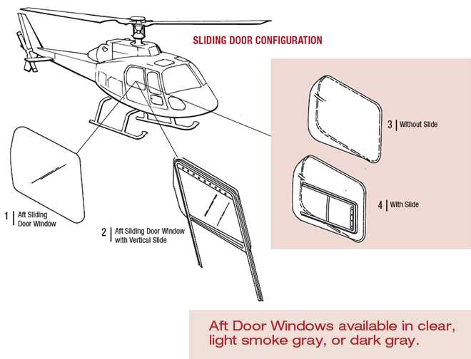
The intricate composition of an aerial vehicle is essential for its functionality and performance. Each component plays a crucial role in ensuring the safety and efficiency of flight operations. A comprehensive exploration of these elements reveals their significance in the overall mechanism.
Various sections contribute to the vehicle’s aerodynamics, stability, and control. By examining these key elements, one gains insight into how they interact to facilitate smooth navigation through the skies. Familiarity with these components enhances the understanding of flight technology.
Furthermore, recognizing the arrangement and relationship between these features helps in appreciating the engineering marvels involved in creating such advanced machinery. This knowledge not only supports enthusiasts but also aids aspiring professionals in the aviation field.

This section will delve into the essential elements that constitute the structure and functionality of rotary-wing aircraft. By examining these components, readers will gain insight into how they contribute to overall performance and maneuverability. Each element plays a vital role in ensuring that the aircraft operates safely and efficiently, highlighting the intricate engineering involved in their design.
Understanding the individual components allows for a deeper appreciation of how they interact and function as a cohesive system. Below is a detailed overview of key elements and their specific purposes.
| Component | Function |
|---|---|
| Rotor Blades | Generate lift and control movement. |
| Tail Assembly | Stabilizes and controls direction. |
| Fuselage | Houses crew and cargo, providing structural integrity. |
| Engine | Powers the rotor and propels the aircraft. |
| Landing Gear | Supports the aircraft during takeoff and landing. |
Key Elements of Rotor Systems

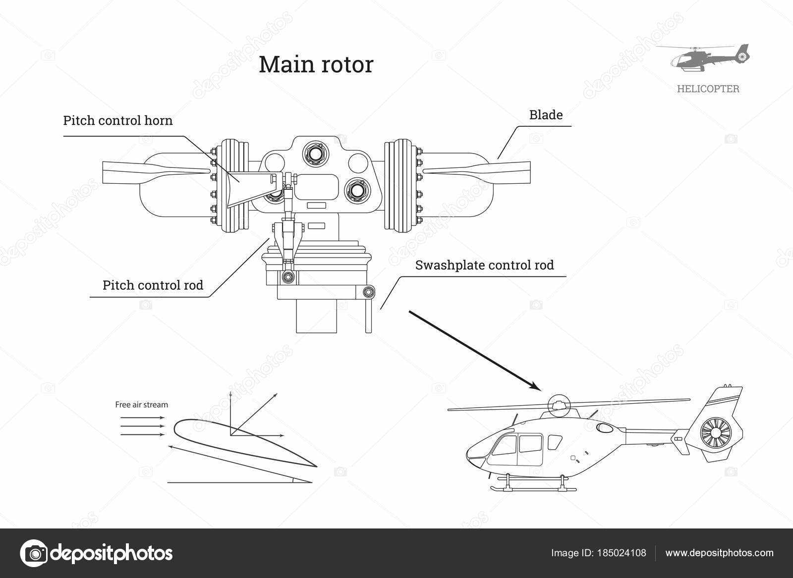
The rotor systems are vital components that play a crucial role in the overall functionality and performance of rotary-wing aircraft. These systems facilitate lift and control, allowing for smooth maneuvering and stability during flight. Understanding the essential elements of these mechanisms provides insight into their operational efficiency and design intricacies.
One of the most significant components is the main rotor blades, which are responsible for generating lift. Their aerodynamic design is optimized to maximize efficiency while minimizing drag. Another key element is the hub, which connects the blades and allows for their rotation. The hub must be designed to withstand significant stress while ensuring the blades can flex and respond to changing flight conditions.
Control mechanisms within the rotor systems enable pilots to adjust the pitch of the blades, influencing the aircraft’s altitude and direction. These mechanisms often include swashplates, which transmit pilot inputs to the blades, ensuring precise control during various maneuvers. The tail rotor is also an essential component, counteracting torque produced by the main rotor, thus maintaining directional stability.
In summary, the rotor systems encompass several critical elements that work together to ensure the safe and efficient operation of rotary-wing aircraft. A thorough understanding of these components is essential for appreciating the complexities of flight dynamics.
Functionality of Helicopter Blades
The efficiency of rotor components plays a crucial role in the overall performance of aerial vehicles. These elements are designed to convert rotational motion into lift, allowing for vertical takeoff and landing. Their shape and angle of attack are meticulously crafted to enhance aerodynamic properties and optimize flight stability.
Lift Generation
One of the primary functions of rotor components is to generate lift. As these elements rotate, they create a difference in air pressure above and below their surfaces. This pressure differential is what allows the aircraft to ascend and maintain altitude. The angle at which these elements cut through the air significantly influences the amount of lift produced.
Stability and Control
In addition to lift generation, rotor components contribute to the stability and maneuverability of the vehicle. By adjusting the pitch, pilots can control the amount of lift and the direction of flight. This adaptability enables swift turns and altitude changes, ensuring a smooth and controlled flight experience. Effective management of these elements is essential for safe navigation and operation.
Importance of the Fuselage Design
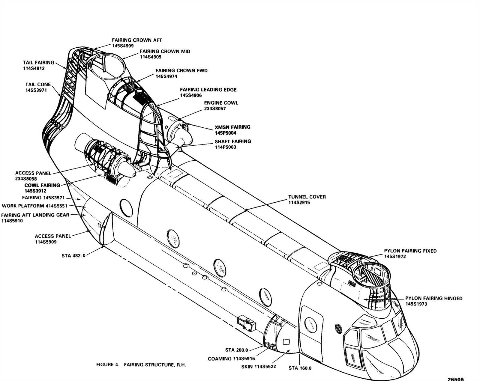
The design of the central structure plays a crucial role in the overall functionality and performance of an aerial vehicle. This framework not only houses various systems but also influences aerodynamics, stability, and safety during operation. A well-engineered outer shell contributes significantly to the effectiveness and efficiency of flight missions.
Aerodynamic Efficiency
A streamlined exterior enhances airflow, reducing drag and allowing for smoother travel. Key considerations in achieving optimal aerodynamics include:
- Shape: A sleek form minimizes resistance against wind.
- Material: Lightweight substances help improve speed and maneuverability.
- Integration: Effective placement of components ensures balanced airflow.
Structural Integrity
Robustness is essential for safety and longevity. Factors influencing structural soundness encompass:
- Stress Distribution: Evenly spread loads prevent weak points.
- Durability: High-quality materials resist wear and environmental factors.
- Design Innovations: Advanced techniques enhance resilience without adding excess weight.
Role of Tail Rotor Assembly
The tail rotor assembly is essential for maintaining balance and control in rotary-wing aircraft. This critical component counteracts the torque generated by the main rotor, ensuring stable flight and maneuverability. Without it, the craft would experience significant yaw, making it challenging for pilots to navigate effectively.
Functionality and Importance
The primary function of the tail rotor assembly is to provide lateral stability. By adjusting the pitch of the rotor blades, it creates thrust that counters the rotational force from the main rotor. This mechanism allows the operator to steer the aircraft and maintain a straight flight path, especially during turns. Additionally, the assembly contributes to overall safety by preventing unwanted spinning, which could lead to loss of control.
Components and Operation
Several key elements comprise the tail rotor assembly, including the rotor blades, gearbox, and control system. The blades are designed to generate lift in the opposite direction of the main rotor’s torque. The gearbox transmits power from the engine, while the control system enables pilots to adjust the rotor blade pitch as needed. This dynamic interaction between components is vital for the aircraft’s agility and responsiveness in various flight conditions.
In summary, the tail rotor assembly plays a crucial role in ensuring stability, control, and safety during flight. Its ability to counteract torque and facilitate directional changes makes it an indispensable part of rotary-wing craft operation.
Navigation Instruments Overview

Understanding the essential tools for guidance is crucial for ensuring safe and effective flight operations. These instruments provide vital information about position, direction, and altitude, allowing pilots to navigate accurately under various conditions.
Key components of navigation tools include:
- Altimeter: Measures the altitude above sea level, crucial for maintaining proper flight levels.
- Heading Indicator: Displays the current direction in which the aircraft is facing, aiding in navigation along predetermined routes.
- Gyroscope: Helps maintain orientation, providing stability and assisting with turns.
- GPS Receiver: Utilizes satellite signals to determine precise location and speed, enhancing navigation capabilities.
- Vertical Speed Indicator: Indicates the rate of ascent or descent, assisting pilots in maintaining desired altitudes.
Effective utilization of these instruments enhances situational awareness and contributes to overall flight safety. Proper training and familiarization with each tool are essential for optimal performance.
Exploring the Cockpit Layout
The control area of an aerial vehicle is a crucial component that significantly influences the operation and safety of flight. This section delves into the organization and arrangement of various instruments and controls that pilots utilize to navigate and manage the aircraft effectively. Understanding the configuration can enhance pilot efficiency and safety during flights.
Key Instruments and Controls
Within the control zone, several essential devices and controls are strategically placed to facilitate smooth operations. Each instrument serves a specific purpose, ensuring that pilots have immediate access to vital information and controls. The layout is designed to optimize visibility and usability, allowing for quick reactions to changing flight conditions.
Functionality of the Layout
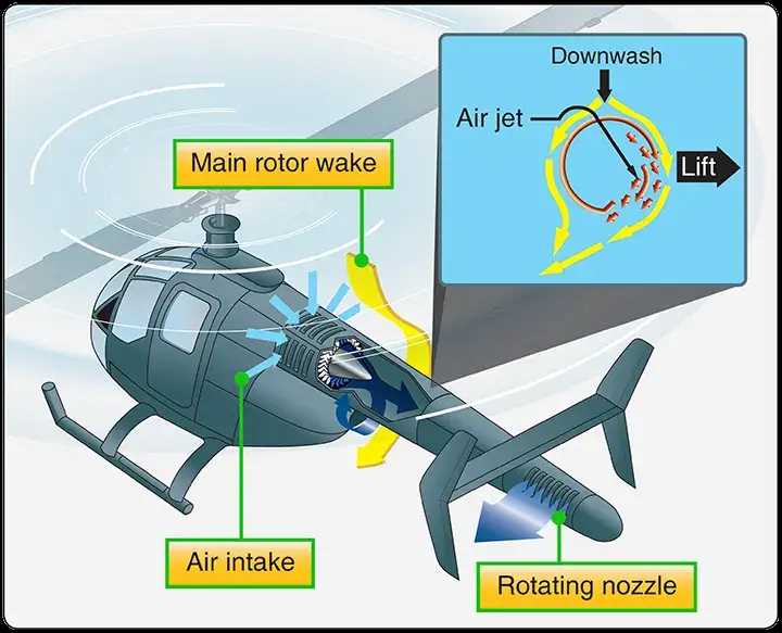
The arrangement of controls promotes intuitive handling, helping pilots maintain focus on their tasks. Various displays provide crucial data regarding altitude, speed, and navigation, while control sticks and pedals ensure precise maneuvering. The efficient design of this workspace enhances the overall flying experience.
| Instrument/Control | Function |
|---|---|
| Altitude Indicator | Displays the current altitude of the vehicle |
| Speedometer | Shows the current speed during flight |
| Navigation System | Assists in route planning and tracking |
| Throttle Control | Regulates engine power and speed |
Powerplant Variants Explained
The choice of power sources is crucial for optimizing performance and efficiency in various aircraft. Different configurations cater to specific operational needs, providing unique advantages and capabilities. Understanding these options enhances knowledge of how propulsion influences flight dynamics.
Types of Power Sources
- Turbine Engines – Known for their high power-to-weight ratio, these engines are commonly used in modern aircraft.
- Piston Engines – Typically found in smaller models, these engines offer simplicity and ease of maintenance.
- Hybrid Systems – Combining conventional engines with electric propulsion, these systems aim to reduce emissions and fuel consumption.
Factors Influencing Selection
- Weight: The overall weight of the propulsion system affects the aircraft’s lift and maneuverability.
- Efficiency: Fuel efficiency plays a vital role in operational costs and range.
- Maintenance: The complexity and frequency of maintenance required can influence operational readiness.
Each variant brings distinct characteristics to the table, allowing operators to tailor their choice based on mission requirements and desired performance outcomes.
Fuel System Specifications
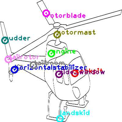
The fuel system plays a critical role in the overall performance and safety of rotorcraft operations. Its design and functionality ensure that the necessary fuel supply is delivered efficiently to the engine, enabling optimal performance and reliability during flight.
Key Components
This assembly consists of several essential elements, including fuel tanks, pumps, filters, and lines. Each component must be meticulously engineered to withstand varying pressure levels and environmental conditions, ensuring a steady flow of fuel even under demanding situations.
Performance Parameters
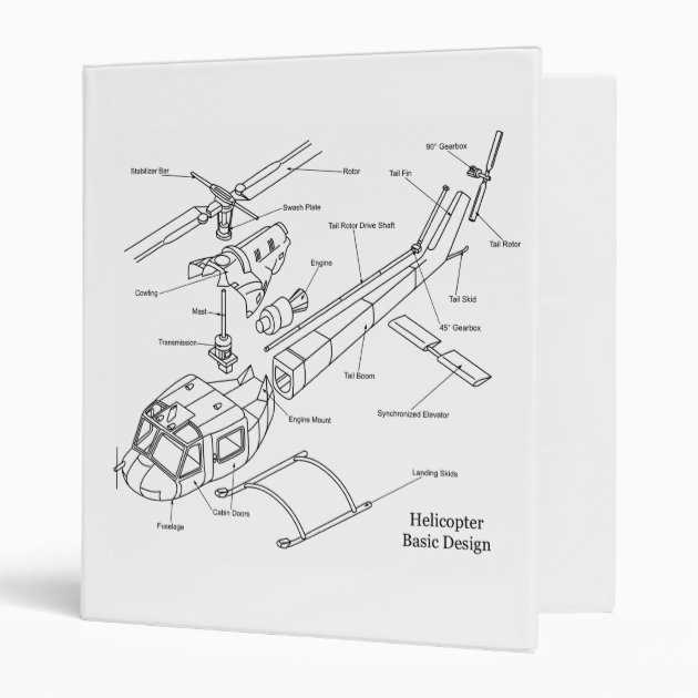
Specifications regarding fuel capacity, pump output, and filter efficiency are vital for assessing the system’s effectiveness. A well-designed fuel assembly not only enhances performance but also contributes to overall operational safety by minimizing the risk of fuel contamination and ensuring proper pressure regulation.
Regular maintenance of these systems is essential to prevent failures and ensure longevity. Operators should adhere to the manufacturer’s recommendations for inspections and servicing to maintain optimal functionality.
Understanding these specifications allows for better decision-making regarding fuel management and system upgrades.
Emergency Equipment Essentials
Ensuring safety during aerial operations necessitates the inclusion of crucial gear designed for emergency scenarios. This equipment plays a vital role in addressing unforeseen situations, providing support and enhancing the security of personnel on board.
Key Components
The following items are indispensable in any flight operation, enhancing readiness and response capabilities:
| Equipment | Description |
|---|---|
| First Aid Kit | A collection of medical supplies to treat minor injuries and stabilize conditions until professional help arrives. |
| Fire Extinguisher | A device used to extinguish small fires, essential for preventing fire-related incidents during emergencies. |
| Emergency Locator Beacon | A signaling device that aids in locating a downed aircraft, significantly improving search and rescue operations. |
| Survival Gear | Includes items like water, food rations, and thermal blankets to ensure survival in case of a forced landing. |
Preparation and Training
Equipping an aerial vehicle with essential emergency items is just the beginning. It is equally important for crew members to undergo regular training on the use of this equipment. Familiarity with emergency procedures ensures that personnel can act swiftly and effectively in critical situations.
Landing Gear Types and Functions

The undercarriage of an aircraft plays a crucial role in its overall functionality and safety. It ensures stability during takeoff, landing, and ground operations. Different types of landing gear are designed to accommodate various operational needs and environmental conditions, providing essential support and protection for the vehicle and its occupants.
Types of Landing Gear
- Fixed Landing Gear: This type remains in a stationary position during flight. It is simple and lightweight, making it suitable for various models.
- Retractable Landing Gear: Designed to retract into the body during flight, this type enhances aerodynamic efficiency and reduces drag.
- Skid Gear: Often used in rugged terrains, skid gear consists of streamlined structures that offer stability without the need for wheels.
- Float Gear: Specifically designed for amphibious vehicles, float gear allows for landing on water surfaces as well as solid ground.
Functions of Landing Gear
- Shock Absorption: Landing gear is equipped with systems that absorb the impact during touchdown, protecting both the vehicle and its occupants.
- Stability: It provides a stable platform during ground operations, enabling safe maneuverability.
- Support: The undercarriage bears the weight of the vehicle while parked and during operation.
- Protection: It protects vital components from ground contact, minimizing damage during landings.
Understanding Control Mechanisms

Control systems play a crucial role in ensuring the stability and maneuverability of aerial vehicles. These systems enable operators to influence the direction and altitude through various inputs. By effectively managing these mechanisms, pilots can achieve precise movements and respond to changing conditions in the air.
Typically, control systems are comprised of several key components that interact to facilitate smooth operation. The cyclic control, for instance, allows for lateral and longitudinal adjustments, while the collective control manages vertical movement. Additionally, the tail rotor contributes to directional stability, counteracting unwanted yaw and ensuring a balanced flight experience.
Understanding these elements is vital for anyone involved in aerial navigation, as they form the foundation for effective piloting. Familiarity with these control mechanisms enhances the ability to anticipate the vehicle’s response and maintain optimal performance under various circumstances.
Avionics and Communication Systems
The integration of advanced technology plays a vital role in the operation of modern flying vehicles. These systems enhance navigation, communication, and overall flight safety, ensuring that operators can maintain optimal control during various phases of flight.
Key components of these systems include:
- Navigation Equipment: Instruments that assist pilots in determining their position and trajectory.
- Communication Tools: Devices that facilitate seamless communication between the pilot and ground control.
- Flight Management Systems: Automated systems that manage various aspects of flight operations, including route planning and fuel efficiency.
- Weather Radar: Equipment that provides real-time data on meteorological conditions, aiding in safe flight navigation.
- Surveillance Systems: Technologies that monitor surrounding air traffic to avoid potential collisions.
These elements are interconnected, working together to create a comprehensive framework that supports safe and efficient flight. Regular maintenance and updates are crucial to ensure the reliability and effectiveness of these sophisticated technologies.