
Understanding the layout of mechanical and electrical systems is essential for efficient maintenance and repairs. By familiarizing yourself with the overall structure, you can quickly identify key elements, making diagnostics and troubleshooting much easier. This guide offers a comprehensive look at how various components are arranged and interconnected within a larger system.
Delving into the finer details of these systems will provide valuable insights into the functionality of each segment. From small connectors to larger assemblies, knowing where each part fits can significantly reduce the time spent on repairs and upgrades. With clear references, you will be able to streamline your work and achieve better results.
Whether you are a seasoned mechanic or a novice, a solid understanding of how the various elements are positioned and interact with one another will greatly improve your ability to maintain and enhance the system’s performance. This resource will guide you through the essential connections, ensuring you can keep everything running smoothly.
Understanding the Structure of Peterbilt 379
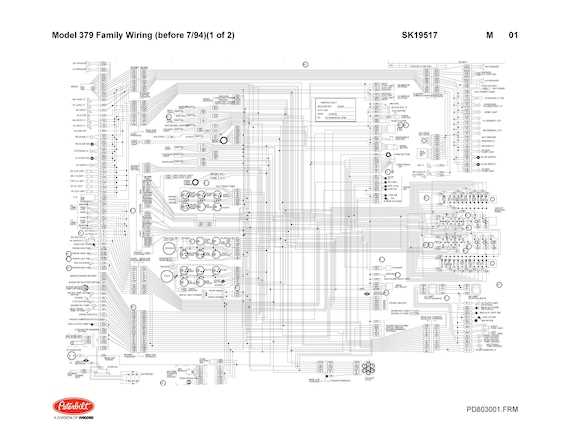
The design of this heavy-duty vehicle is based on a complex and robust framework that supports both performance and durability. Each component is meticulously positioned to ensure seamless interaction, contributing to the overall efficiency of the vehicle. The configuration is well-suited for demanding environments, ensuring reliability even under challenging conditions.
Core Components and Their Functions
The main framework includes various interconnected sections, each playing a critical role in maintaining balance and power distribution. From the support structures to the mechanisms that drive the system, every element is designed to optimize the vehicle’s operation. The arrangement allows for smooth performance, reducing wear and tear while maximizing operational longevity.
Mechanical and Electrical Integration
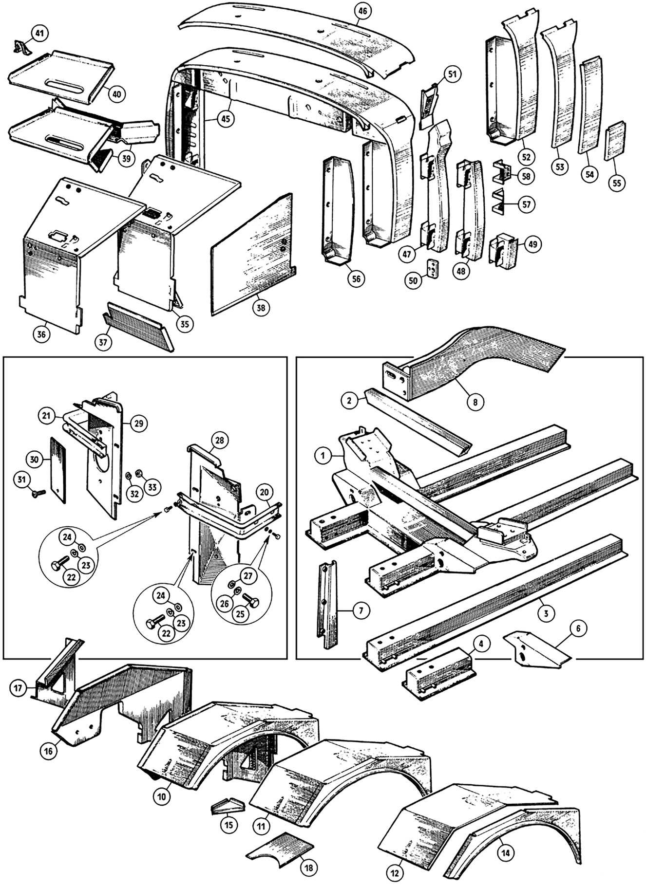
One of the standout features is the integration of mechanical and electrical systems, ensuring that different subsystems work in harmony. The engineering of these systems emphasizes precision, reducing the likelihood of
Key Components in the Peterbilt 379
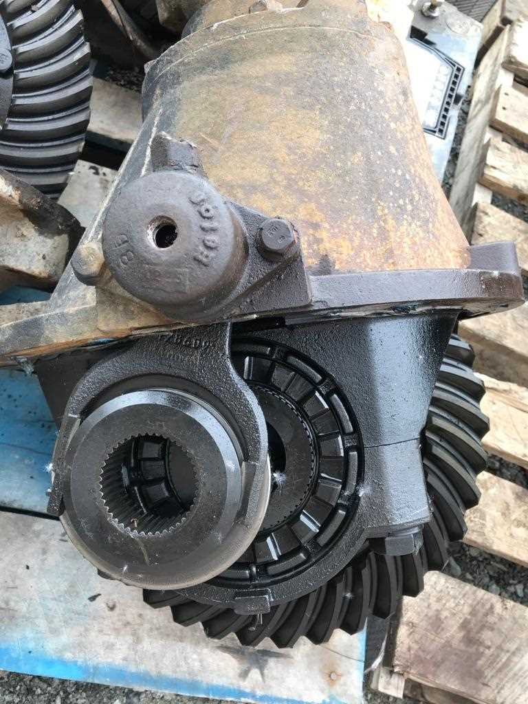
Understanding the essential elements of a heavy-duty vehicle is crucial for ensuring optimal performance and maintenance. The main structural and mechanical components play significant roles in how effectively the vehicle operates, contributing to both safety and reliability.
Chassis and Frame: The backbone of the vehicle, the chassis provides the necessary support for the engine, cab, and other key systems. Its design ensures durability and the ability to withstand heavy loads over long distances.
Engine System: The powerhouse of the vehicle, responsible for delivering the torque and horsepower needed for transporting goods over various terrains. The engine is typically designed for efficiency and longevity, often utilizing advanced technology to reduce emissions and fuel consumption.
Suspension and Axles: These components ensure a smooth ride and stability, especially when the vehicle is under heavy load. The suspension system absorbs shock from uneven roads, while the axles distribute the vehicle’s weight and provide power to the wheels.
Common Replacement Parts and Their Functions
Vehicles often require periodic replacements of key components to ensure optimal performance and safety on the road. Understanding the purpose and role of these elements helps in making informed decisions during maintenance. In this section, we will explore some frequently substituted components and their specific functions in keeping a vehicle running smoothly.
One of the most common elements requiring attention is the braking system. Brake pads, for instance, are essential for ensuring safe deceleration, converting kinetic energy into heat through friction. Regular inspections and replacements of these pads prevent wear that could compromise stopping power.
Another critical component often needing replacement is the alternator. This device plays a key
Chassis Layout and Assembly Details
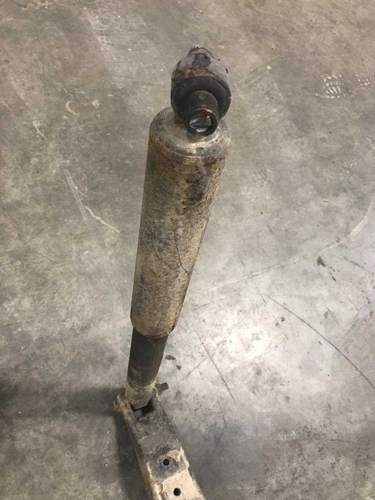
The arrangement of the main framework and the assembly process play a critical role in ensuring the strength and reliability of large vehicles. Understanding the structure and how each component connects within the framework helps maintain both functionality and durability over time.
Structural Components: The core structure consists of various interconnected elements that support the overall weight and allow the vehicle to handle significant loads. These elements are precisely engineered to balance stability and flexibility, which is crucial for long-term performance.
Assembly Techniques: Proper assembly requires detailed attention to the alignment and positioning of each part within the framework. Specialized techniques ensure that each connection is secure, reducing wear and tear and minimizing the need for frequent adjustments.
Maintenance Considerations: Over time, regular inspections and adjustments are necessary to keep the framework in optimal condition. Addressing potential issues early on helps extend the lifespan of the vehicle and ensures
Identifying Crucial Engine Components
Understanding the key elements of a vehicle’s engine is essential for proper maintenance and troubleshooting. By familiarizing yourself with the different systems and parts that make up the engine, you can better diagnose issues and ensure smooth operation. This section will highlight important components to focus on, emphasizing their roles in engine performance and longevity.
Main Structural Elements
- Cylinder Block: The foundation of the engine where cylinders are located, providing the housing for key moving parts.
- Crankshaft: Converts the up-and-down motion of pistons into rotational movement to power the vehicle.
- Camshaft: Responsible for controlling the opening and closing of valves, coordinating with the crankshaft.
Supporting Systems
Brake System Overview for Peterbilt 379
The braking mechanism is a crucial component of any heavy-duty vehicle, ensuring safe operation and control during transit. This system comprises various elements that work together to facilitate effective stopping power and reliability under different driving conditions.
Key components of the braking system include:
- Brake Pedal: The interface for the driver, allowing manual activation of the braking process.
- Master Cylinder: Converts the force applied to the brake pedal into hydraulic pressure.
- Brake Lines: Transport hydraulic fluid from the master cylinder to the brake assemblies at each wheel.
- Brake Calipers: Act to squeeze the brake pads against the rotors, generating the friction needed to slow the vehicle.
- Brake Pads: Friction materials that press against the rotors to create stopping force.
- Brake Rotors: Metal discs that rotate with the wheels and interact with the brake pads.
Maintenance of the braking mechanism is essential for optimal performance and safety. Regular checks should include:
- Inspecting brake fluid levels and ensuring there are no leaks.
- Examining the condition of brake pads and rotors for wear.
- Testing the brake pedal for responsiveness.
- Ensuring all connections and components are secure and functioning properly.
Understanding the intricacies of the braking system can enhance the safety and efficiency of heavy-duty vehicles, contributing to smoother operations on the road.
Suspension System Parts and Configuration
The suspension framework is crucial for ensuring a smooth ride and optimal handling characteristics in heavy-duty vehicles. It comprises various components that work in harmony to absorb shocks, maintain stability, and enhance overall performance. Understanding the configuration and functionality of these elements is essential for effective maintenance and troubleshooting.
Key Components: The primary elements of the suspension include the leaf springs, which provide support and flexibility, and the shock absorbers, which mitigate oscillations and improve ride quality. Additionally, airbags may be integrated into the system to further enhance comfort and load-carrying capabilities.
Configuration Insights: The arrangement of these components can vary based on design specifications and intended use. A well-designed system allows for easy adjustments, enabling operators to optimize performance based on varying loads and road conditions. Regular inspection of the suspension setup is recommended to ensure all components function as intended, promoting longevity and reliability.
Electrical System Breakdown and Diagram
This section provides a detailed overview of the electrical architecture found in heavy-duty vehicles, highlighting its components and their interconnections. Understanding this system is crucial for effective troubleshooting and maintenance, as it ensures the proper functioning of various electronic and electrical devices within the vehicle.
Key Components of the Electrical System
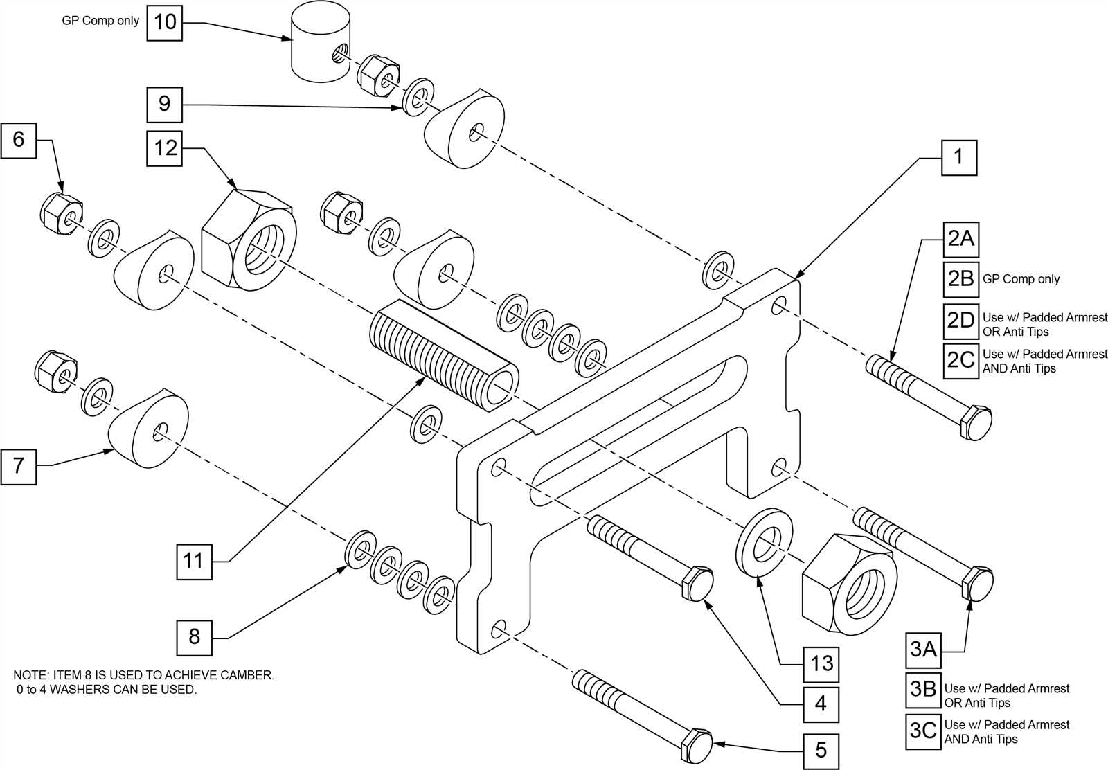
The electrical system encompasses several critical elements, each serving a specific function. These components work in harmony to facilitate the efficient operation of the vehicle’s electrical systems.
Component Function Batteries Provide electrical power for starting the engine and powering auxiliary systems. Alternator Charges the batteries and powers electrical systems while the engine is running. Starter Motor Initiates engine operation by turning the flywheel. Fuses and Relays Protect circuits from overload and control the flow of electricity to various components. Wiring Harness Connects all electrical components and facilitates communication between them. Understanding the Layout

The configuration of the electrical system is designed to optimize performance and safety. Each component is strategically placed to reduce the risk of damage and improve accessibility for maintenance. Familiarity with the layout aids in diagnosing issues and making necessary repairs efficiently.
Transmission and Drivetrain Component Locations
Understanding the positioning of transmission and drivetrain components is crucial for effective maintenance and repair. These systems are vital for transferring power from the engine to the wheels, ensuring smooth operation and performance. Familiarity with their locations aids in troubleshooting issues and performing upgrades or replacements.
Key Components Overview
Various elements within the drivetrain play essential roles in vehicle functionality. Identifying these components and their locations helps streamline service procedures and ensures optimal vehicle performance.
Component Location Table
Component Location Transmission Mounted directly behind the engine, secured to the chassis. Driveshaft Extends from the transmission to the rear axle, typically located underneath the vehicle. Rear Differential Situated at the rear axle assembly, connected to the driveshaft. Transfer Case Located adjacent to the transmission in four-wheel-drive configurations. Axles Extend from the differential to the wheels, located at the rear of the vehicle. Cooling System Parts and Layout
The cooling mechanism is vital for maintaining optimal operating temperatures within heavy-duty vehicles. This system prevents overheating, ensuring that the engine operates efficiently and prolongs its lifespan. Understanding the components involved and their arrangement can help in troubleshooting and maintenance tasks.
- Radiator: Responsible for dissipating heat from the coolant fluid. It plays a crucial role in regulating engine temperature.
- Water Pump: Circulates coolant throughout the system, ensuring efficient heat exchange and maintaining pressure.
- Thermostat: Regulates the flow of coolant based on temperature, opening and closing to maintain the desired heat level.
- Coolant Reservoir: Stores excess coolant, allowing for thermal expansion and helping to maintain proper fluid levels in the system.
- Hoses: Flexible tubes that transport coolant between various components, ensuring a continuous flow and preventing leaks.
- Fan: Aids in airflow through the radiator, enhancing cooling efficiency, especially during low-speed operation.
The configuration of these elements can vary based on the specific requirements of the vehicle, but their fundamental functions remain consistent across different models. Proper maintenance and understanding of this system can prevent overheating and ensure long-lasting performance.
Exhaust System Components and Setup
The exhaust system plays a crucial role in managing emissions and ensuring optimal engine performance. Understanding the various elements and their configurations is essential for maintaining efficiency and compliance with environmental regulations. This section delves into the primary components involved and their setup to achieve an effective exhaust management system.
Key Elements of the Exhaust System
At the heart of the exhaust system are several vital components, including the manifold, catalytic converter, and muffler. The manifold serves as the initial collector of exhaust gases, channeling them away from the engine. Following this, the catalytic converter plays a pivotal role in reducing harmful emissions through chemical reactions. Finally, the muffler helps to minimize noise produced by the engine’s exhaust gases, ensuring a quieter operation.
Installation Considerations
When setting up the exhaust system, it is essential to pay attention to proper alignment and secure connections to prevent leaks. Each component should be installed according to the manufacturer’s specifications, ensuring that the flow of exhaust gases is unobstructed. Regular inspections and maintenance of the system will also enhance longevity and performance, contributing to a smoother driving experience.