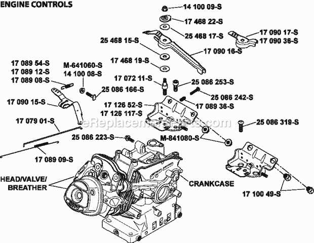
Understanding the layout and structure of mechanical elements is essential for proper maintenance and repairs. This detailed guide offers a clear view of how various elements are arranged and interconnected within a specific engine model. It helps you to easily identify and locate individual components.
The layout information is crucial for troubleshooting, allowing you to pinpoint potential issues quickly. By examining the arrangement, you can make informed decisions on the replacement or repair of mechanical elements, ensuring the engine runs efficiently.
Exploring the arrangement of mechanical components can simplify complex processes, making maintenance easier. Whether you’re a professional or a DIY enthusiast, this guide provides you with the essential knowledge needed to handle different mechanical challenges.
Engine Overview
This section provides a general description of the robust small engine known for its durability and versatility in various applications. Designed to deliver efficient performance in a wide range of environments, this model stands out for its reliability and engineering precision, making it ideal for machines requiring consistent power output.
Main Features
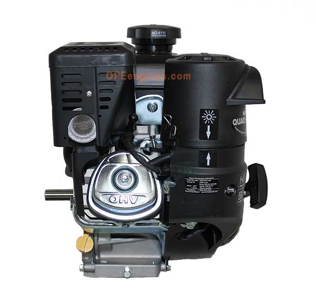
- Air-cooling system to maintain optimal temperature
- Efficient fuel consumption for extended operational hours
- Durable construction suitable for heavy-duty tasks
- Compact design, facilitating easy installation in different equipment
Performance and Applications
This engine is widely used in construction, landscaping, and agricultural machinery due to its excellent power-to-weight ratio. Its design allows for smooth operation, even in demanding conditions, making it a reliable choice for professionals seeking long-term value.
Main Components of the CH270
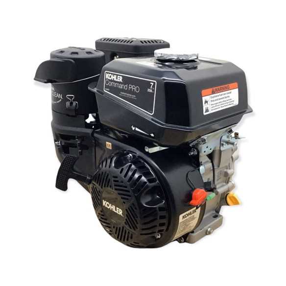
This engine model features several key elements that work together to ensure efficient performance and durability. Understanding the primary components and their functions can help in maintaining and troubleshooting the unit.
Engine Block and Cylinder
- The main structure housing the internal parts.
- Contains the cylinder where combustion occurs.
- Provides support for other components like the crankshaft and camshaft.
Fuel System
- Includes a carburetor for mixing air and fuel.
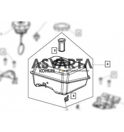
- Fuel tank designed to store the gasoline needed for operation.
- Fuel lines connecting the tank to the carburetor, ensuring smooth delivery.
- Ignition Coil – This component amplifies the electrical voltage needed to create a spark in the spark plug.
- Spark Plug – Responsible for producing the spark that ignites the fuel-air mixture in the engine.
- Flywheel Magnet – Generates the initial electrical pulse as it rotates past the ignition coil.
Air Filtration System Details
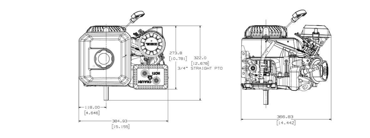
The air purification mechanism is crucial for maintaining the performance and longevity of the engine. By filtering out dust and other particles, this system ensures that only clean air reaches the internal components, minimizing wear and optimizing combustion efficiency. A well-functioning filtration setup helps prevent blockages and overheating issues, which can lead to costly repairs.
Modern filtration units often consist of a pre-filter and a main filter. The pre-filter captures larger debris, while the main filter traps finer particles. This two-stage process increases the overall efficiency of the system, ensuring longer intervals between maintenance checks and smoother engine operation.
Regular inspection and cleaning of the air filter is recommended to avoid reduced airflow, which can affect engine performance. Replacing the filter as part of routine maintenance helps ensure optimal air intake and protects the engine from damage over time.
Ignition System Breakdown
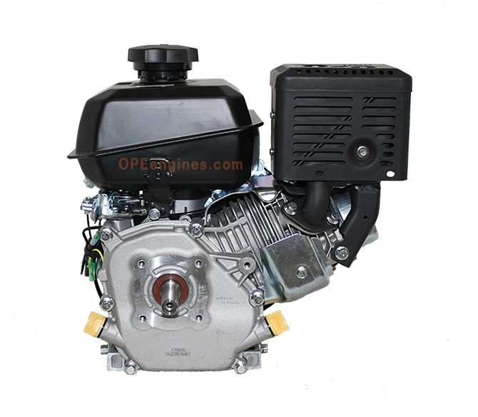
The ignition system ensures a proper start for the engine by creating the necessary spark at the right time. This process involves multiple components working in harmony to generate and control the electrical charge required to ignite the fuel mixture within the combustion chamber.
Main Components of the Ignition System
Operational Sequence
- The flywheel rotates, generating a magnetic field near the ignition coil.
- The ignition coil amplifies this magnetic energy,
Fuel Supply Mechanism
The fuel supply mechanism ensures that the engine receives a steady flow of fuel for efficient operation. It consists of several components that work together to regulate the fuel intake, maintaining the right balance between fuel and air to achieve optimal combustion. Understanding the structure of these elements helps in troubleshooting and maintaining engine performance.
Components of the Fuel System
Component Function Fuel Tank Stores the fuel before it enters the system. Fuel Filter Removes impurities from the fuel to protect the engine. Cooling System Layout
The cooling system is essential for maintaining an optimal temperature in the engine during operation. This section outlines the components responsible for regulating heat and preventing overheating, ensuring that the machine operates smoothly and efficiently.
- Cooling fins: These structures are designed to dissipate heat from the engine, allowing for natural air cooling.
- Fan: A mechanical device that enhances airflow around the engine to speed up the cooling process.
- Air intake: Directs external air towards the engine, contributing to effective temperature control.
- Exhaust system: Plays a role in reducing heat by expelling hot gases away from the engine area.
Each component in the cooling system works together to prevent overheating, ensuring consistent performance even under heavy use.
Exhaust Configuration and Parts

The exhaust system plays a crucial role in the efficiency and performance of an engine, ensuring that harmful gases are expelled while maintaining optimal airflow. Understanding its components is essential for effective maintenance and troubleshooting.
At the core of the exhaust configuration is the manifold, which collects gases from multiple cylinders and directs them into the exhaust pipe. This component must be constructed from durable materials to withstand high temperatures and pressures.
Following the manifold, the muffler serves to reduce noise produced by the engine. Its design often includes internal baffles and chambers that help in sound attenuation without significantly hindering gas flow.
Additionally, the catalytic converter plays a vital role in minimizing emissions by converting harmful substances into less harmful ones. Regular inspection of this component is crucial for maintaining compliance with environmental regulations.
Finally, the exhaust pipe connects all these elements, guiding gases away from the engine. It is important to ensure that the pipe is free of blockages and leaks to maintain proper engine performance.
Piston and Cylinder Assembly
The piston and cylinder assembly is a crucial component of internal combustion engines, playing a vital role in converting fuel energy into mechanical power. This assembly consists of two main parts: the piston, which moves up and down within the cylinder, and the cylinder itself, which houses the piston and contains the combustion process. Understanding the function and design of these elements is essential for maintaining engine performance and efficiency.
Functionality
The primary function of the piston is to create pressure during the combustion cycle. As the fuel-air mixture ignites, the resulting explosion forces the piston downward, translating this linear motion into rotational power via the crankshaft. The cylinder, on the other hand, provides a controlled environment for this process, ensuring proper sealing and alignment to maximize efficiency.
Maintenance Considerations
Regular maintenance of the piston and cylinder assembly is critical to prevent wear and tear, which can lead to performance issues. Common practices include checking for proper lubrication, inspecting for any signs of damage, and ensuring the assembly is free from carbon buildup. Addressing these factors promptly can significantly extend the lifespan of the engine components and enhance overall functionality.
Lubrication System Diagram
The lubrication system is essential for the smooth operation of any engine, ensuring that all moving parts receive adequate oil flow. This system minimizes friction, reduces wear, and helps maintain optimal performance. Understanding the components and their interactions within this system is crucial for effective maintenance and troubleshooting.
Components of the Lubrication System
The primary elements of the lubrication system include the oil pump, filters, and various passages that distribute oil throughout the engine. The oil pump draws lubricant from the reservoir and pushes it through the filter to remove contaminants. Clean oil is then delivered to critical areas, providing a protective layer that enhances efficiency.
Functionality and Maintenance
Regular maintenance of the lubrication system is vital for preventing engine failure. Periodic oil changes, filter replacements, and inspections of the pump and lines ensure that the system operates effectively. Monitoring oil levels and quality can help identify potential issues before they escalate, leading to longer engine life and improved reliability.
Valve Train Components
The valve train is a critical assembly in an engine, responsible for controlling the timing and operation of the valves. This system ensures that the intake and exhaust processes occur at the appropriate moments, which is essential for optimal engine performance.
Key elements of the valve train include the camshaft, which regulates the opening and closing of the valves, and the pushrods, which transfer motion from the camshaft to the rocker arms. Additionally, rocker arms play a vital role in converting the linear motion of the pushrods into the angular motion required to operate the valves.
Another important component is the valve springs, which provide the necessary force to close the valves after they have been opened. This assembly must work in harmony to maintain the engine’s efficiency and power output. Regular maintenance and inspection of these components are crucial for preventing potential engine issues.
Mounting and Frame Parts
The structural components that support and secure the engine play a crucial role in ensuring stability and proper alignment. These elements are essential for maintaining the integrity of the machine during operation.
Typically, the framework consists of durable materials designed to withstand vibrations and impact. It includes various brackets, supports, and fasteners that work together to create a robust assembly. Understanding the arrangement and function of each component is vital for effective maintenance and troubleshooting.
Additionally, the mounting hardware is responsible for affixing the engine to its base, allowing for efficient transfer of power and movement. Regular inspection of these elements can help identify any signs of wear or damage, ensuring long-term performance and safety.