Understanding the structure and organization of various elements in industrial equipment is crucial for efficient maintenance and repair. This guide offers a detailed breakdown of key assemblies, helping operators and technicians quickly identify necessary components and their proper configurations. With a clear visual representation, it becomes much easier to comprehend how individual elements are interconnected, ensuring smooth operation and preventing potential issues.
By closely examining the layout of each segment, users can gain valuable insights into how the system functions as a whole. This knowledge is essential for timely interventions, accurate replacements, and overall machine upkeep. Whether you’re troubleshooting or performing routine checks, a well-organized schematic is an indispensable tool for any professional.
Understanding Manitou Component Schematics
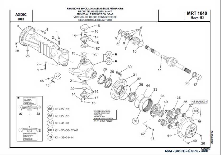
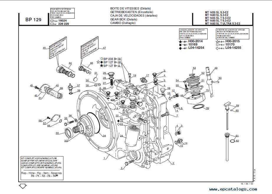
When examining equipment designs, understanding how different elements are represented visually is crucial for efficient maintenance and repair. By studying technical illustrations, one can quickly grasp how various systems are interconnected and identify specific elements within complex assemblies. These illustrations serve as a road map for troubleshooting and servicing, ensuring that each component functions as intended.
Key Elements of Technical Schematics
- Connections: Visual guides show how different systems link together, allowing for better insight into operational flow.
- Labels: Clear and concise labeling helps to identify individual sections, making navigation through the blueprint smoother.
- Detailed Views: In-depth representations of certain systems offer a closer look at complex structures
How to Read Equipment Blueprints
Understanding equipment blueprints is essential for anyone working with machinery or construction. These drawings contain crucial information about the structure, assembly, and functioning of various components. By interpreting these technical illustrations correctly, you can ensure accurate implementation, maintenance, and troubleshooting for complex systems.
Key Elements in Equipment Blueprints
Blueprints typically consist of several sections, each providing specific data. The main components include symbols, lines, and measurements, which represent different mechanical and structural features. Familiarity with these notations allows for precise communication and understanding of the system’s layout and operational flow.
Symbol Meaning Solid Line Key Parts in Manitou Machines
In modern heavy machinery, essential components ensure seamless operation across various tasks. Each unit relies on specialized mechanical and hydraulic elements to handle different operational demands. Understanding these key elements is critical to maintaining efficient performance and prolonging the lifespan of the equipment.
Engine and Transmission
The power source is at the heart of any machine. A robust engine ensures the unit delivers consistent strength, while the transmission system controls movement and power distribution. Both work in harmony to provide optimal efficiency and operational control, making them foundational to the overall performance.
Hydraulic System
Another crucial component is the hydraulic system, which allows the equipment to handle heavy lifting and precise
Steps to Locate Spare Parts
Finding the right components for your equipment can be a straightforward process when you follow a structured approach. This section will guide you through the key steps needed to identify and order the necessary items for repair or maintenance.
- Start by gathering all relevant information about your machinery, including model and serial numbers. This will ensure you have the correct data to search for compatible parts.
- Consult the user manual or technical documentation to understand the specifications of the required components. These resources often contain detailed breakdowns and lists of essential elements.
- Use online platforms or the manufacturer’s website to search for the component catalog. Many platforms offer search tools that allow you to filter by model and category, making the process quicker.
- Check for availability
Decoding Symbols in Diagrams

Understanding the various symbols found in technical blueprints is essential for accurate interpretation and efficient work. These symbols serve as a universal language that simplifies complex representations, making it easier to follow the layout and connections of various components. By learning how to identify and interpret these symbols, users can gain better insight into the functionality and assembly of the equipment.
Geometric shapes are often used to represent different physical elements. For instance, circles might indicate rotational components, while squares and rectangles are commonly associated with structural parts. These visual cues help differentiate between types of elements at a glance.
Arrows and lines are another common feature in such blueprints, guiding the user through various movements or fluid connections.
Choosing Replacement Parts for Manitou
Selecting the appropriate components for machinery is crucial to ensure optimal performance and longevity. Understanding the specifications and compatibility of various elements can help users make informed decisions, thereby enhancing the overall functionality of the equipment.
When considering replacements, it is important to follow a structured approach:
- Identify the Issue: Start by diagnosing the problem accurately. Whether it’s a performance decline or a specific malfunction, pinpointing the root cause is essential.
- Consult the Manual: Refer to the equipment’s guidebook to gather details on specifications and recommended substitutes. This document often provides valuable insights into compatible options.
- Research Options: Explore various suppliers and manufacturers to find suitable alternatives. Make sure to review user feedback and ratings to gauge reliability.
- Verify Compatibility: Double-check that the chosen components align with the existing machinery model. Compatibility is vital for ensuring seamless operation.
- Consider Quality: Opt for high-quality components that meet or exceed industry standards. Investing in superior materials can lead to improved performance and durability.
- Assess Cost: While price is a factor, it should not be the sole consideration. Weigh the costs against quality and longevity to determine the best value.
By following these guidelines, users can confidently choose suitable replacements, ensuring the machinery remains efficient and reliable over time.
Why Diagrams Are Essential for Repairs
Visual representations play a crucial role in the repair process, offering clear insights into the components and their interconnections. These illustrations simplify complex assemblies, making it easier for technicians to understand how each part functions within the larger system.
Having access to well-structured visuals enhances the accuracy of repairs by allowing users to identify the specific elements that require attention. This precision not only saves time but also reduces the likelihood of errors, ensuring that the correct procedures are followed during maintenance tasks.
Furthermore, such representations serve as valuable references for troubleshooting. When faced with a malfunction, technicians can quickly consult these guides to pinpoint potential issues, leading to more effective solutions. The clarity and organization provided by these visuals contribute significantly to a smoother and more efficient repair experience.
Common Issues Found Through Diagrams
Visual representations of machinery components serve as invaluable tools for identifying prevalent problems that may arise during operation and maintenance. By examining these illustrations, users can pinpoint potential areas of concern, ensuring timely interventions and enhancing overall efficiency.
Wear and Tear on Components
One frequent issue highlighted in these visuals is the gradual deterioration of various elements due to regular usage. Identifying signs of wear, such as cracks, deformation, or discoloration, allows for proactive replacement or repair, thus preventing more significant malfunctions.
Misalignment and Installation Errors

Another critical concern illustrated in these representations is the improper alignment of parts during assembly. Such discrepancies can lead to inefficient functioning or even damage. Recognizing these misalignments early on facilitates accurate adjustments, ensuring optimal performance.
How to Identify Parts by Model
Recognizing components based on specific models is essential for effective maintenance and repair. By understanding the characteristics associated with various models, you can ensure you obtain the correct elements needed for optimal functionality. This section will guide you through the process of accurately identifying essential components to streamline your tasks.
Utilizing Model Numbers
Model numbers serve as crucial identifiers for different components. Typically located on the equipment itself, these alphanumeric codes provide insights into the specifications and variations of each element. When searching for a particular item, always reference the model number to confirm compatibility.
Consulting Manufacturer Resources
Accessing the manufacturer’s resources is invaluable when determining the correct components. Official websites, manuals, and technical support can offer detailed information regarding specific models and their corresponding elements. Utilize these resources to cross-reference your findings and ensure accuracy.
Best Practices for Using Parts Schematics
Understanding visual representations of components is essential for efficient maintenance and repair. By following established guidelines, users can enhance their familiarity with these illustrations, leading to more effective troubleshooting and assembly processes.
1. Familiarize Yourself with the Key Elements
Before diving into the schematics, take time to recognize the fundamental symbols and notations. Identifying components and their relationships within the visual aid can significantly streamline your approach. Familiarity with the layout will enable you to quickly locate the necessary elements, minimizing confusion during repairs.
2. Cross-Reference with Manuals
Always cross-check the information found in the visual aids with user manuals or technical documents. This practice ensures accuracy and provides additional context that may not be immediately clear from the illustrations alone. By integrating multiple resources, you can develop a comprehensive understanding of the assembly, which is crucial for successful maintenance.
Manitou Maintenance Using Diagrams
Effective upkeep of machinery often involves visual representations that simplify complex systems. By employing illustrations, operators can identify components, troubleshoot issues, and streamline maintenance procedures. This approach not only enhances understanding but also promotes efficiency and safety during servicing tasks.
Utilizing these visual tools allows technicians to quickly reference the arrangement and functions of different elements. This is crucial for ensuring that each part is correctly maintained or replaced, minimizing downtime and extending the lifespan of the equipment.
Component Maintenance Action Frequency Hydraulic System Inspect for leaks and replace fluid Monthly Drive Belts Check tension and wear Every 500 hours Filters Replace air and oil filters Every 1000 hours Tires Inspect for damage and check pressure Weekly Incorporating visual guides into routine maintenance helps in systematically addressing each part, ensuring that no element is overlooked. This structured approach enhances reliability and operational efficiency, contributing to the overall performance of the equipment.