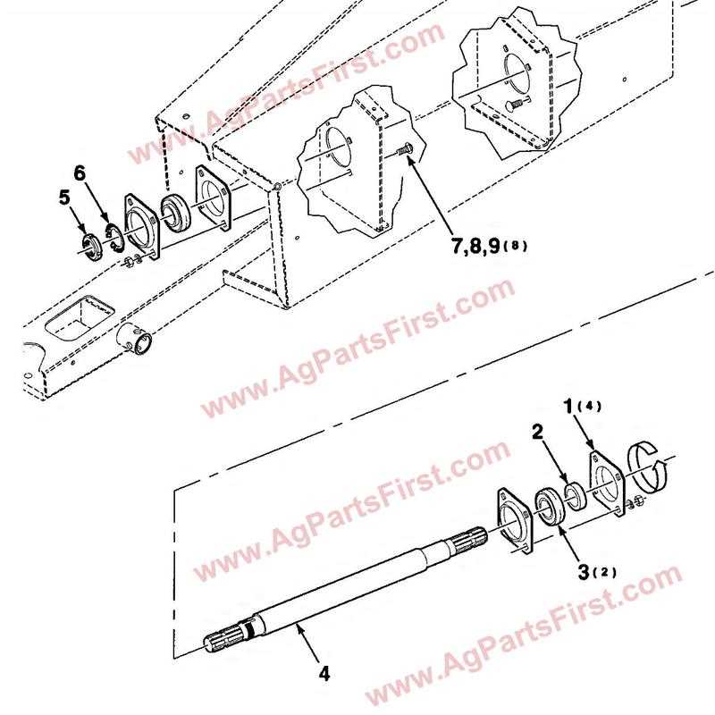
Understanding the intricate workings of mechanical systems requires careful attention to each individual element and its placement within the overall structure. The section that follows will guide you through the essentials of a specific agricultural machinery assembly, shedding light on how various components interconnect to form a cohesive and functional unit. This exploration will provide clarity on the purpose and interaction of each piece.
Each mechanical element plays a vital role in ensuring the smooth operation of the machine. From pivotal components that drive movement to smaller parts that support and stabilize, the intricate assembly of these elements is essential to maintaining optimal performance. A well-maintained setup not only extends the lifespan of the equipment but also ensures efficiency and reliability during operation.
In the next sections, we will delve into
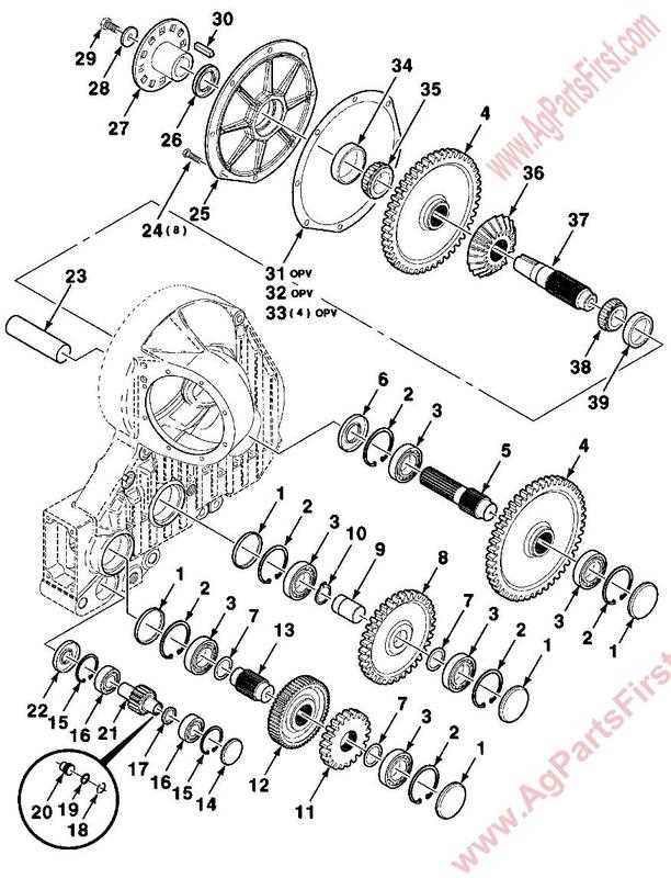
New Idea 5209 Parts Diagram Overview
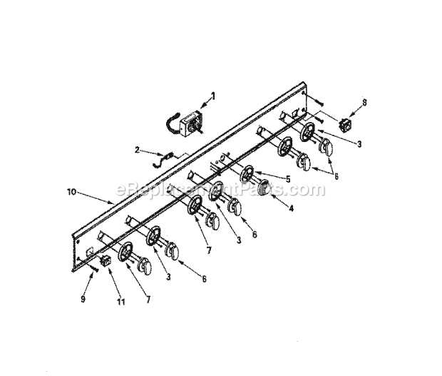
This section provides a detailed outline of the key elements and components essential for maintaining the equipment. Understanding the structure and layout of various mechanical and operational parts allows users to ensure proper function and address any potential issues that may arise during use. Each component is intricately designed to fit within the system, contributing to the overall performance of the machine.
By examining the arrangement of these elements, users can quickly identify areas that require maintenance, replacement, or adjustment, ensuring long-term reliability and smooth operation. Regular review of these components is crucial for optimal efficiency and avoiding disruptions.
Key Components of the Machine
The machine is built with several critical elements that work together to ensure optimal performance. Each component plays a significant role in the overall functionality, contributing to efficiency and durability. Understanding these elements can help maintain and troubleshoot the system effectively.
- Drivetrain: Responsible for transferring power from the engine to various moving parts, ensuring smooth operation.
- Frame: The sturdy foundation that supports the entire structure, designed to handle the stress and load during use.
- Cutting Mechanism: A sharp and efficient tool for processing materials, ensuring precise cuts and reducing wastage.
- Hydraulic System: Provides the necessary force to operate different parts, ensuring seamless and powerful movement.
- Control Panel: The interface that allows the operator to manage and adjust settings for efficient operation.
- Safety Features:
Exploring the Cutting Mechanism
The cutting mechanism is a crucial component that ensures efficient and precise operation. Understanding how it functions can help in maintaining optimal performance and extending its lifespan. This section delves into the intricacies of the mechanism, providing insights into its core elements and their interaction.
Main Components
Several key parts work together to form the cutting system. Each one plays a vital role in achieving the desired results.
- Blades: These are responsible for the actual cutting, crafted from durable materials to withstand wear and tear.
- Drive system: This powers the blades, ensuring they move at the correct speed and with the required force.
- Adjustment controls: These allow for customization of the cutting depth and angle to suit various needs.
Operational Process

The process begins with the drive system engaging the blades, setting them into motion. As the blades rotate or move,
Understanding the Gearbox Assembly
The gearbox is a crucial component that facilitates the transfer of power within mechanical systems. It plays a vital role in regulating speed and torque to ensure smooth operation. Grasping its configuration and function is essential for anyone looking to maintain or repair mechanical equipment.
Below is an outline of the main elements involved in this assembly:
- Input Shaft: The primary connection that delivers rotational energy from the engine to the assembly.
- Gears: Various sizes of gears engage with each other to control speed and force transmission.
- Output Shaft: Receives the adjusted power and transmits it to the final destination, such as wheels or another system.
- Hydraulic Pump: Responsible for generating flow and pressure within the system.
- Hydraulic Fluid: Acts as the medium for power transmission, lubricating components and dissipating heat.
- Actuators: Devices that convert hydraulic energy into mechanical work, such as cylinders or motors.
- Control Valves: Regulate the flow and direction of hydraulic fluid, allowing precise control of movement.
- Filters: Ensure the cleanliness of hydraulic fluid, protecting the system from contaminants.
- Identify components for inspection.
- Check for leaks or wear.
- Replace hydraulic fluid as needed.
- Test system pressure and flow rates.
- Universal Joints: These allow the shaft to flex and rotate at varying angles, ensuring smooth power transfer.
- Shielding: Protective covers that prevent debris and damage to the shaft during operation.
- Yokes: Connectors at each end of the shaft that attach to the tractor and implement, facilitating power transfer.
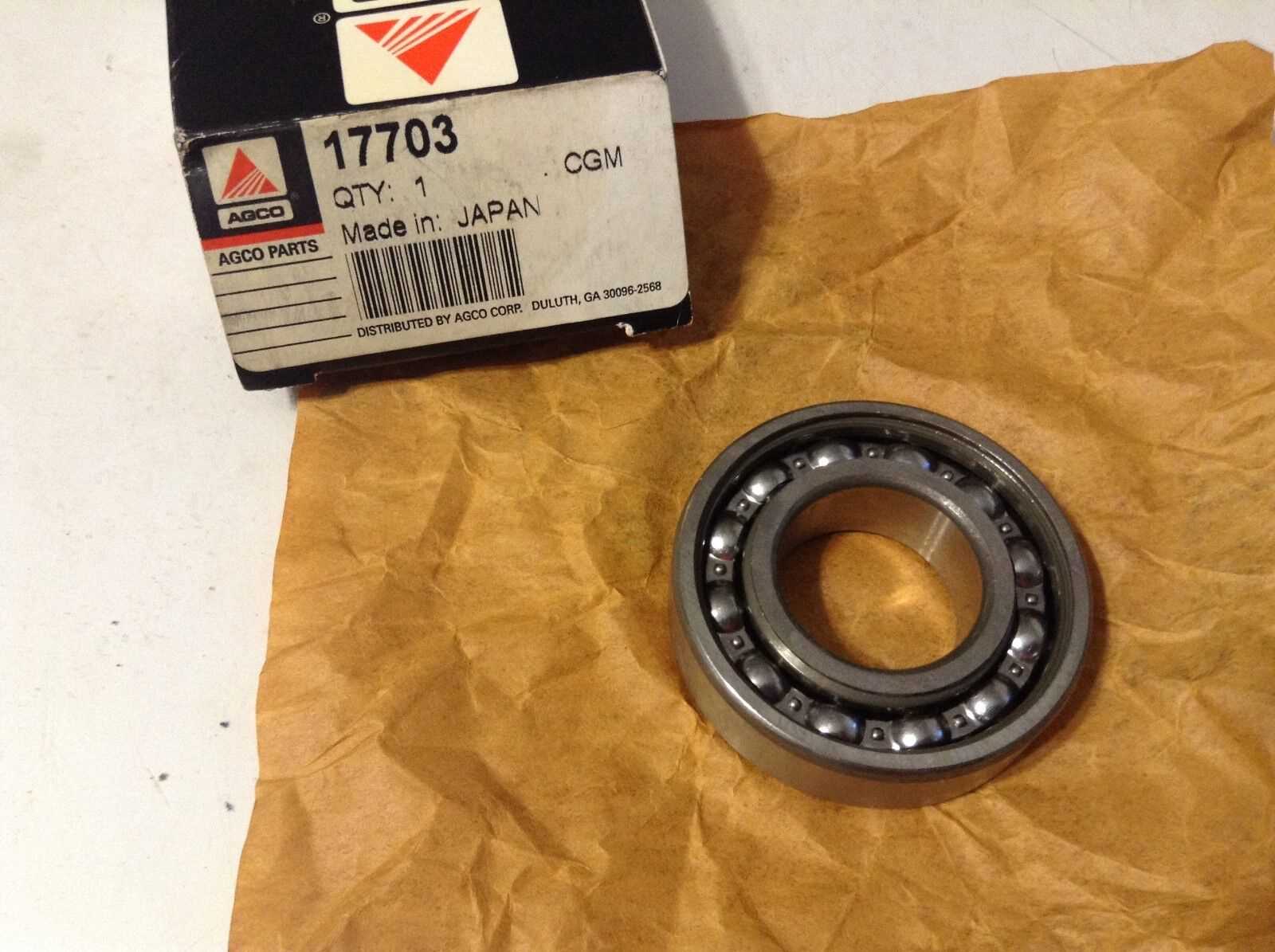
- Bearings: Support the shaft and reduce friction during rotation, enhancing efficiency and lifespan.
- Powering rotary cutters, balers, and seeders.
- Driving pumps, generators, and other auxiliary equipment.
- Enabling efficient operation of various agricultural tasks.
- Gather all necessary tools and components before starting the installation process.
- Ensure that the vehicle or device is parked on a stable, flat surface.
- Consult the manufacturer’s specifications for compatibility and weight limits.
- Align the hitch with the designated mounting points on the vehicle.
- Insert the hitch pin through the holes to secure it in place.
- Tighten all bolts and fasteners according to the torque specifications provided.
- Attach safety chains, ensuring they are crossed underneath for added security.
- Check the alignment and stability of the connection before use.
Blades and Their Maintenance
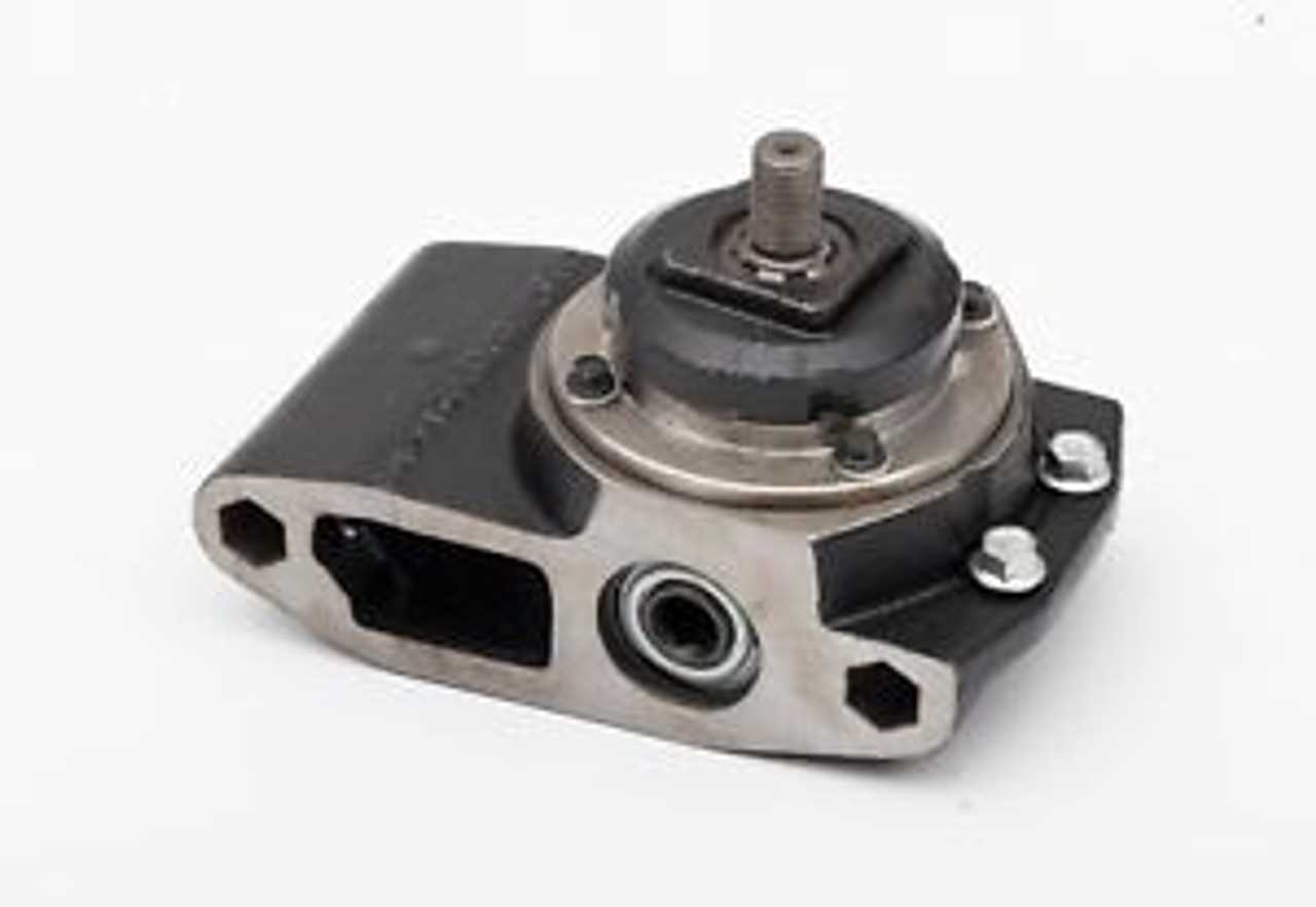
Proper care of cutting components is essential to ensure long-term efficiency and performance. Regular inspections and upkeep help to prevent issues that may arise from wear and tear, and extend the functionality of the equipment.
Inspection Guidelines
Blades should be checked frequently for signs of damage or dullness. Even minor wear can affect cutting performance, leading to inefficiency or uneven results. Pay attention to the sharpness and condition of the edges, ensuring they remain free of nicks or deformities.
Sharpening and Replacement
Regular sharpening is crucial to maintain optimal performance. If blades become too dull, they should be sharpened or replaced depending on their condition. Below is a table summarizing the recommended maintenance actions based on the blade’s state:
Condition Action Frequency Hydraulic System Breakdown
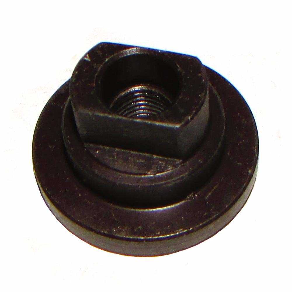
The hydraulic system is a crucial component in various machinery, facilitating efficient operation through the transmission of power via fluid. Understanding the different elements that make up this system is essential for effective maintenance and troubleshooting.
Key components of the hydraulic system include:
When analyzing the hydraulic system, it is vital to consider how these components interact to achieve optimal functionality. Regular inspections and maintenance can prevent common issues, ensuring longevity and performance.
By understanding the breakdown of the hydraulic system, operators can effectively troubleshoot issues and maintain the machinery in peak condition.
How the Drive System Works
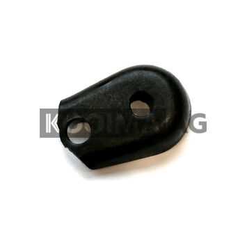
The functionality of a drive mechanism is essential for the effective operation of machinery. This system is responsible for translating power into motion, ensuring that components work in harmony to achieve desired outcomes. Understanding its principles can enhance the efficiency and reliability of equipment.
At its core, the drive mechanism comprises several key elements that collaborate to convert energy sources into mechanical movement. The primary components typically include motors, gears, and belts. Each part plays a specific role in this process, contributing to the overall performance.
Motors serve as the powerhouse, providing the necessary energy to initiate movement. They can be electric, hydraulic, or pneumatic, depending on the design and requirements of the equipment. The choice of motor influences the system’s speed, torque, and overall efficiency.
Gears act as crucial intermediaries that adjust the speed and torque transmitted from the motor to the moving parts. By altering the gear ratios, the system can adapt to different operational needs, enhancing both performance and control.
Belt systems are often employed to facilitate the transfer of motion between components, providing flexibility and reducing the risk of wear. They help in synchronizing movements, ensuring that all parts operate smoothly and efficiently together.
In summary, the drive mechanism’s design and assembly are pivotal for optimal operation. By integrating various components effectively, it can deliver reliable performance across different applications.
Adjusting the Swath Roller
Proper calibration of the swath roller is essential for optimal performance in various applications. This adjustment ensures that the equipment functions efficiently, allowing for effective material handling and uniform distribution. By fine-tuning the roller’s position, users can enhance the overall effectiveness of the machinery.
To begin, locate the adjustment mechanism typically situated near the swath roller assembly. Utilize the appropriate tools to modify the height and angle as needed. It is crucial to follow the manufacturer’s recommendations for specific measurements to achieve the desired results. Ensuring that the roller is level will significantly improve its performance, reducing wear and tear on both the roller and the surrounding components.
After making the adjustments, it is advisable to conduct a test run. Observe the roller’s operation, paying attention to any irregularities in performance. If necessary, make further tweaks to achieve the optimal setting. Regular maintenance and periodic re-evaluation of the swath roller’s adjustment will contribute to prolonged equipment life and improved efficiency.
Identifying Bearing Locations
Understanding the placement of various components within a mechanical assembly is crucial for optimal functionality. Bearings play a vital role in reducing friction and supporting moving parts, thus their precise location is essential for smooth operation and longevity. Recognizing where these elements are situated within the system can aid in troubleshooting and maintenance tasks.
The following table outlines common bearing types and their typical placements in machinery:
Bearing Type Common Locations Function Ball Bearings Motor shafts, gearboxes Reduce friction between rotating parts Roller Bearings Wheels, conveyor systems Support heavy loads while minimizing rolling resistance Thrust Bearings Axle assemblies, rotary applications Handle axial loads and maintain alignment Proper identification of bearing locations facilitates effective inspection and maintenance, ensuring that machinery operates at peak performance and reduces the risk of unexpected failures.
Tips for Replacing Cutter Bar Parts
When it comes to maintaining agricultural equipment, understanding how to effectively change out components can significantly enhance performance and longevity. This section offers practical guidance to ensure a smooth replacement process.
Preparation Before Replacement
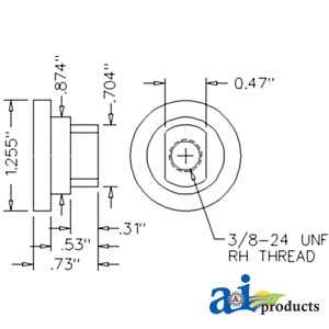
Prior to beginning any replacement, gather all necessary tools and components. Make sure to consult the user manual to identify the specific requirements for your equipment model. Ensure safety measures are in place by disconnecting the power source and using protective gear.
Step-by-Step Replacement Process
Start by carefully removing the old component, taking note of the configuration and positioning. This will aid in the proper installation of the new part. Follow a systematic approach by replacing each item one at a time, verifying compatibility to avoid any complications. Once the new piece is in place, conduct a thorough inspection to ensure everything is securely fastened.
Detailed Look at PTO Shaft
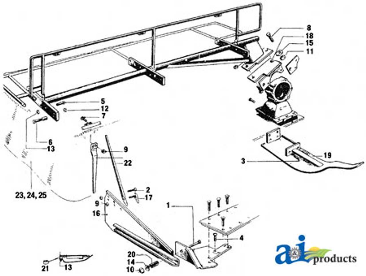
The power take-off (PTO) shaft is a crucial component in agricultural and industrial machinery. It serves as a vital link, transmitting power from the engine to various implements and attachments. Understanding its construction and functionality is essential for ensuring optimal performance and maintenance.
Structure and Components
The PTO shaft consists of several key elements, each playing a significant role in its operation:
Functionality and Applications
The PTO shaft is designed to handle significant torque and speed variations, making it suitable for a range of applications:
Regular inspection and maintenance of the PTO shaft can prevent common issues such as misalignment and wear, ensuring reliable performance and extending the lifespan of the machinery.
Mounting and Hitching Guide
This section provides essential instructions for securely attaching and setting up equipment. Proper installation is crucial for optimal performance and safety during use. Following these guidelines will help ensure a successful connection and reliable operation.
Preparation Steps
Installation Procedure
Common Wear Parts and Replacements
In any mechanical system, certain components are subject to regular usage and wear over time. Understanding these crucial elements is essential for maintaining optimal functionality and extending the lifespan of the equipment. This section delves into frequently replaced components that may exhibit signs of degradation, highlighting the importance of timely maintenance to ensure efficiency and reliability.
Typical items that require attention include belts, seals, and filters. These elements play vital roles in the overall operation, and their deterioration can lead to decreased performance or even system failures. Regular inspections and timely replacements not only prevent unexpected downtime but also enhance the longevity of the entire system.
Additionally, understanding the signs of wear can help in identifying when these components should be replaced. Common indicators include unusual noises, decreased efficiency, and visible damage. By staying proactive in addressing these wear components, operators can maintain smooth and effective operation.