Understanding the configuration of mechanical assemblies is crucial for maintaining and repairing any equipment. By familiarizing yourself with the layout and relationships between individual elements, it becomes easier to identify what needs attention during routine checks or when something goes wrong. Clear visual representations can significantly enhance this process, providing a helpful reference for those aiming to ensure optimal functionality.
Each element within a system plays a specific role in ensuring smooth operation, and recognizing how these parts interact can aid in efficient troubleshooting. Whether you’re performing regular maintenance or addressing a specific issue, having a clear view of all interconnected elements will empower you to make informed decisions. This guide will assist in visualizing and understanding these components for effective upkeep and care.
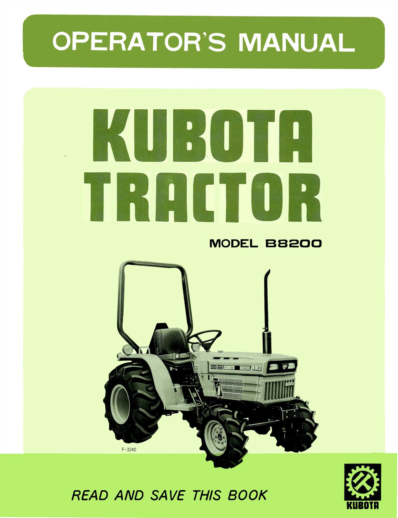
Kubota B8200 Parts Diagram Overview

The layout of components in this model provides a detailed understanding of how various elements interact within the machine. This schematic illustration simplifies maintenance tasks and helps users identify key sections for repairs or upgrades. By visually breaking down the equipment, it becomes easier to navigate its structure, ensuring that each element fits its purpose efficiently.
Key Component Arrangement
The arrangement highlights essential areas such as the engine, transmission, and hydraulic systems. This organized breakdown allows for quick reference, ensuring smooth operation and efficient troubleshooting. Identifying and understanding how different mechanisms are placed can significantly improve handling and performance.
Streamlined Maintenance
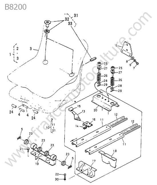
With a clear visual representation, servicing the equipment becomes more intuitive. Each section is presented logically, aiding in fast and accurate repairs. The clear depiction ensures that users can manage upkeep efficiently without unnecessary delays.
Engine Components and Layout
The internal structure of the engine is designed to ensure efficient performance and longevity. Its layout involves various interconnected systems that contribute to the smooth operation of the machine, focusing on fuel efficiency, power delivery, and heat management.
- Cylinder Block: The foundation of the engine, housing key components like pistons and crankshaft, it supports other systems and ensures durability.
- Pistons and Crankshaft: These work in tandem to convert the combustion force into rotational energy, driving other mechanical parts.
- Cooling System: Essential for maintaining optimal temperature, this system includes a radiator, water pump, and hoses, circulating coolant to prevent overheating.
- Fuel Injection: This system delivers fuel into the engine for combustion, optimizing fuel consumption and ensuring smooth operation.
- Exhaust System: The final stage of engine operation, responsible for removing exhaust gases, ensuring emissions are minimized and the engine runs efficiently.
Each component is carefully arranged within the engine bay to maximize space, accessibility for maintenance, and integration with other systems.
Transmission System Parts Identification
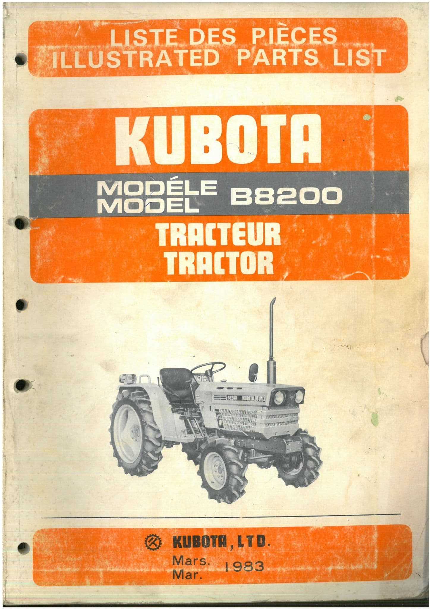
The transmission mechanism is a crucial component that allows the smooth transfer of power from the engine to the wheels. It ensures efficient operation, making it essential to understand the various interconnected elements within this system. Each component plays a vital role in ensuring optimal performance and longevity.
- Gearbox Assembly: This is the core unit responsible for shifting gears, ensuring proper speed and torque distribution.
- Clutch Mechanism: Engages and disengages power flow between the engine and the transmission, allowing smooth transitions between different gears.
- Drive Shafts: These shafts transfer torque from the transmission to the wheels, maintaining power flow and movement.
- Differential Unit: Ensures balanced power distribution between the wheels, especially during turns, for consistent traction.
Identifying and understanding these components is essential for efficient system maintenance and repair, ensuring longevity and optimal functioning of the entire vehicle system.
Hydraulic System Diagram for Kubota B8200
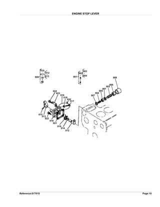
The fluid control setup in this model operates through a series of interconnected components designed to manage pressure and fluid flow. The system is engineered to power various mechanical functions, ensuring smooth and efficient performance. The core of this mechanism lies in its ability to handle both lifting and movement operations with precision, allowing for enhanced versatility in use. This section provides an overview of how the hydraulic flow is distributed across the machine, enabling users to understand the general operation.
Main Components of the Hydraulic Circuit
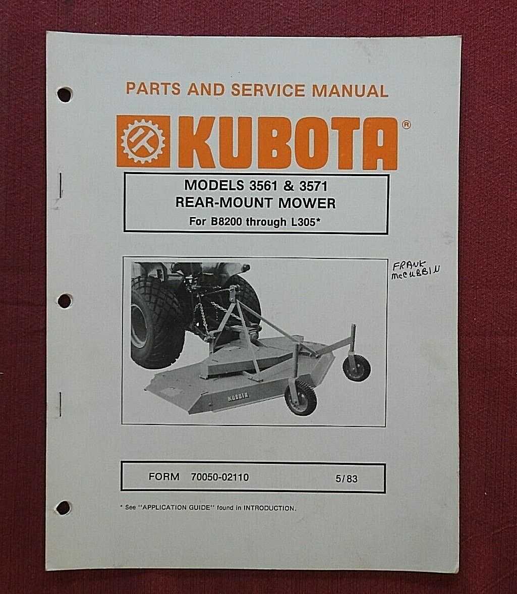
The system includes several key elements that work in unison to regulate fluid movement. The pump acts as the heart of the setup, pushing the fluid into the necessary channels. Control valves direct the pressurized fluid to specific parts of the machine, ensuring each operation receives the correct force. Return lines complete the circuit by guiding the fluid back into the reservoir for recirculation.
Functionality and Adjustments
Each part of the hydraulic structure plays a role in maintaining balance within the system. Adjustments can be made to tailor the performance to different tasks, such as changing the pressure settings or regulating flow speed. Understanding how these adjustments impact the overall system is essential for optimizing functionality. Ensuring proper maintenance and fluid levels is also crucial for longevity.
Steering Mechanism and Linkage Parts
The steering system plays a crucial role in ensuring precise control and smooth navigation. This essential component connects the operator’s input to the movement of the wheels, allowing for effective turning and handling on various terrains. Its design integrates multiple elements that work in unison, providing responsive and efficient movement, especially in demanding environments.
Steering linkages are vital for translating the movement from the control system to the wheels. These connections must remain intact and free from wear to ensure that the turning response remains accurate and reliable. Proper maintenance of these components can extend the lifespan of the equipment and enhance operational safety.
Maintaining the entire steering system ensures that all components, including the mechanical connections, are functioning optimally. Regular inspections for wear and alignment help avoid potential issues, ensuring consistent performance and safety during operation.
Electrical System Parts Breakdown
The electrical setup of machinery is crucial for its optimal operation and functionality. Understanding the components that comprise this system can enhance maintenance and troubleshooting efforts. Each element plays a significant role in ensuring the effective transmission of electrical energy, contributing to the overall performance of the equipment.
Wiring Harness: This essential component serves as the main channel for electrical flow, connecting various parts throughout the machine. A well-maintained wiring harness is vital for preventing malfunctions.
Battery: The power source for the electrical system, providing the necessary voltage to start the engine and power various accessories. Regular checks are necessary to ensure its reliability.
Starter Motor: This device initiates the engine’s operation by converting electrical energy from the battery into mechanical energy. Its efficiency is crucial for a smooth start.
Alternator: Responsible for generating electricity while the engine runs, this component replenishes the battery and powers electrical systems, ensuring consistent performance.
Fuses and Relays: These protective elements safeguard the electrical system from overloads and short circuits. Regular inspection can prevent costly damages and ensure safety.
Understanding the intricacies of the electrical components allows for better management and servicing, leading to increased longevity and performance of the machinery.
Fuel System Components and Diagram
The fuel system is crucial for the efficient operation of any engine. It ensures that the necessary fuel is delivered to the combustion chamber, facilitating the energy conversion process. Understanding the various elements of this system is essential for maintenance and troubleshooting.
Main Components of the Fuel System
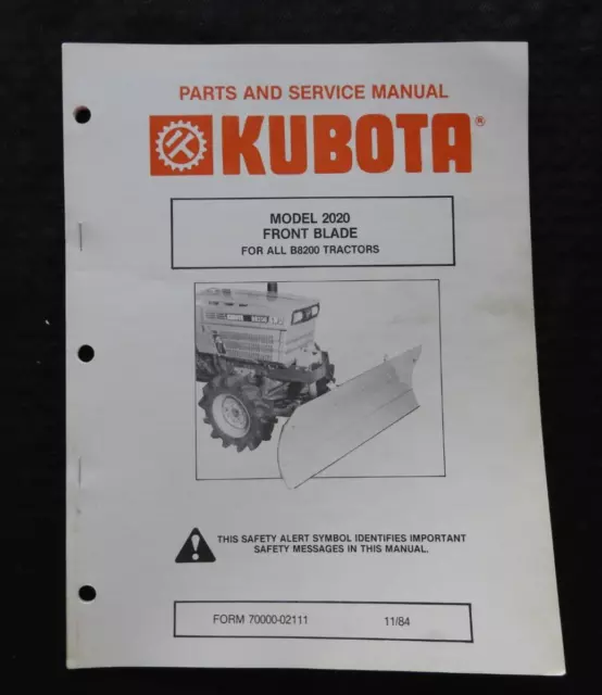
This system consists of several key elements that work together to manage fuel flow. Each component plays a specific role in maintaining optimal performance.
| Component | Description |
|---|---|
| Fuel Tank | Stores the fuel for the engine. |
| Fuel Pump | Delivers fuel from the tank to the engine. |
| Fuel Filter | Cleans the fuel before it enters the engine. |
| Fuel Injector | Sprays fuel into the combustion chamber. |
| Fuel Lines | Transport fuel between the tank and the engine. |
The flow of fuel begins at the tank, where it is drawn by the pump. Once filtered, the fuel is injected into the combustion chamber, where it mixes with air for ignition. Proper maintenance of these components ensures reliability and efficiency.
Front and Rear Axle Parts Overview
This section provides a comprehensive look at the essential components of the front and rear axles. Understanding these elements is crucial for maintaining optimal performance and ensuring the longevity of the vehicle. Each component plays a significant role in the overall functionality of the drive system, contributing to stability and maneuverability.
| Component Name | Description |
|---|---|
| Axle Housing | The main structure that encases the axle, providing support and protection for internal components. |
| Bearings | Elements that facilitate smooth rotation of the axle, reducing friction and wear. |
| Drive Shaft | A critical component that transmits power from the engine to the wheels, enabling movement. |
| Gear Assembly | A set of gears that transfers power and adjusts torque for improved performance during operation. |
| Suspension Links | Connecting elements that support the suspension system, aiding in shock absorption and stability. |
Cooling System Parts Identification
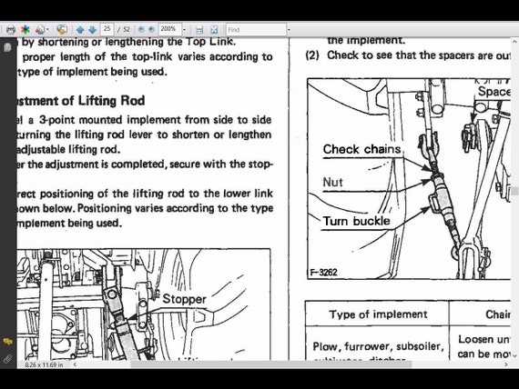
The cooling mechanism is vital for maintaining optimal operating temperatures in any machinery. Understanding the components involved is essential for efficient maintenance and troubleshooting. This section will help you recognize and identify various elements within the cooling structure, ensuring proper function and longevity.
Key Components of the Cooling Mechanism
Central to the cooling system are several crucial elements that work together to dissipate heat. The radiator plays a significant role in transferring heat away from the engine, while the water pump circulates coolant throughout the system. Additionally, hoses and clamps connect these components, ensuring the proper flow of liquid for effective temperature regulation.
Importance of Regular Inspection
Routine examination of the cooling structure is necessary to prevent overheating and potential engine damage. Look for signs of wear, leaks, or blockages in hoses and connections. Ensuring that the radiator is clean and unobstructed can significantly enhance the efficiency of the entire system, prolonging the life of the equipment.
Brake System Components and Layout
The braking system is a critical aspect of machinery operation, ensuring safe and efficient stopping capabilities. Understanding the various elements that comprise this system can enhance maintenance and troubleshooting efforts.
Key components of the braking system include:
- Brake Pedal: The interface for the operator to engage the braking mechanism.
- Master Cylinder: Responsible for converting pedal movement into hydraulic pressure.
- Brake Lines: These carry the hydraulic fluid from the master cylinder to the brake assemblies.
- Brake Calipers: Act on the brake pads, applying pressure to the brake disc.
- Brake Pads: Provide the necessary friction to slow down or stop the vehicle.
- Brake Discs: Rotating components against which the pads exert force.
Additionally, the layout of the braking system can vary depending on the design and intended use of the equipment. Common arrangements include:
- Single Circuit: Utilizes one set of brake components to control all wheels.
- Dual Circuit: Offers redundancy by having separate circuits for front and rear brakes.
- Hydraulic Assist: Enhances braking power through hydraulic systems for improved efficiency.
Proper maintenance of each component is essential to ensure optimal performance and safety. Regular inspections can help identify wear and potential issues before they become significant problems.
Attachments and Implements Parts Diagram
This section provides an overview of various accessories and tools designed for enhancing the functionality of compact machinery. Understanding the configuration and components involved is essential for effective maintenance and operation. The following details offer insight into the essential elements that make up these attachments, ensuring users can efficiently identify and manage each component.
Essential Components Overview
Each attachment consists of critical components that contribute to its overall performance. These elements include fasteners, brackets, and hydraulic connections that work in unison to achieve desired results. Familiarity with these parts allows for smoother integration and operation of the implements.
Maintenance and Replacement Considerations
Regular inspection and upkeep of accessories are vital for optimal performance. Users should pay attention to wear and tear on key elements and replace them as needed to maintain functionality. Knowing how to identify which parts require attention can significantly extend the lifespan of the implements.