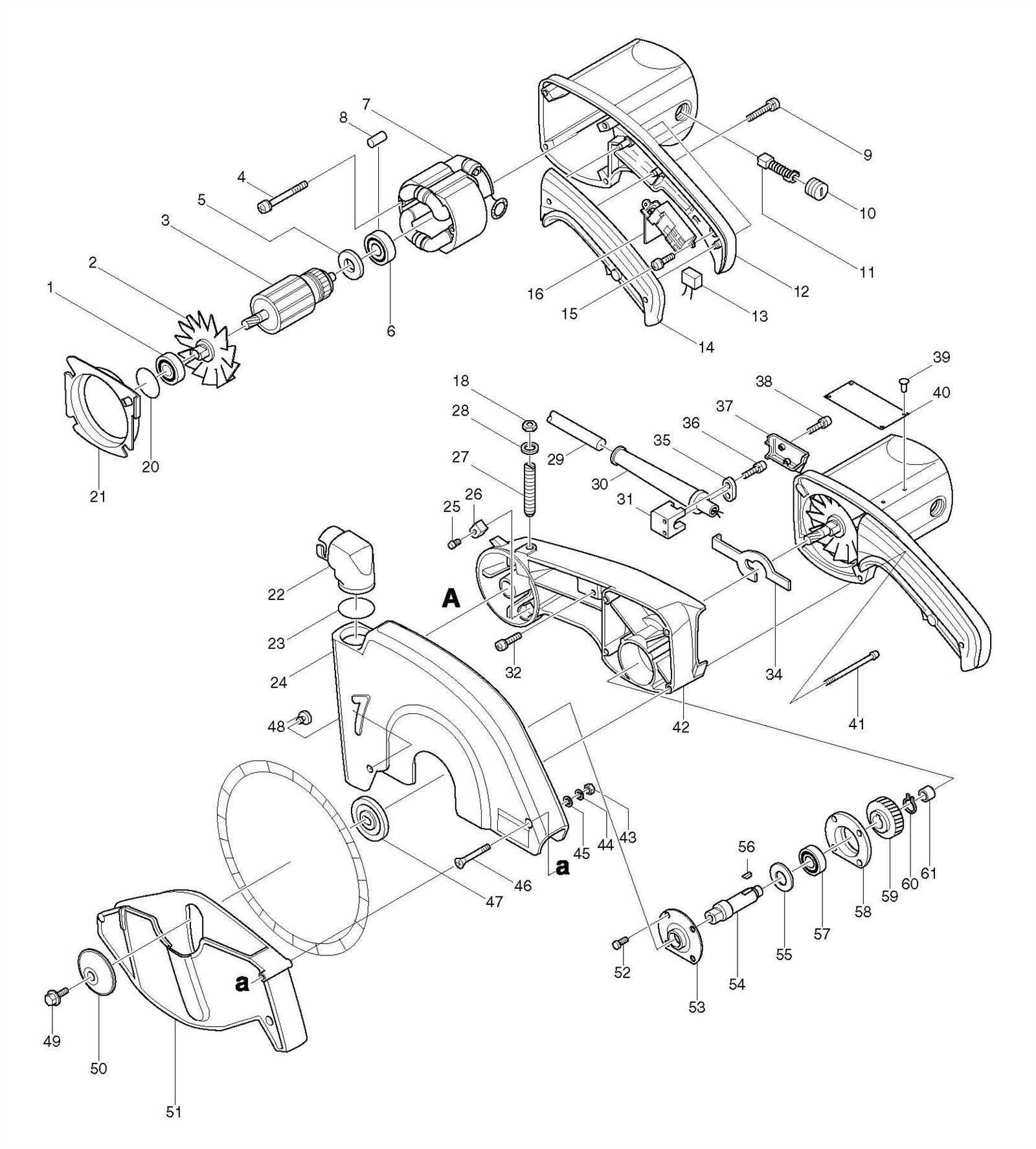
The detailed illustration of components is an essential tool for understanding the internal structure of various equipment. Whether you’re a seasoned technician or a novice, these breakdowns provide a clear visual reference to the individual elements that make up the whole. This approach simplifies the process of identifying, replacing, or maintaining different elements within a tool or device.
By examining each section closely, users can gain insights into the precise assembly process, ensuring smoother repairs and better maintenance. With clear guidance on where each element fits and how it functions, keeping your equipment in top shape becomes significantly easier.
Whether you’re looking to troubleshoot an issue or simply understand the inner workings, this approach offers an invaluable resource for keeping your machinery operational and efficient.
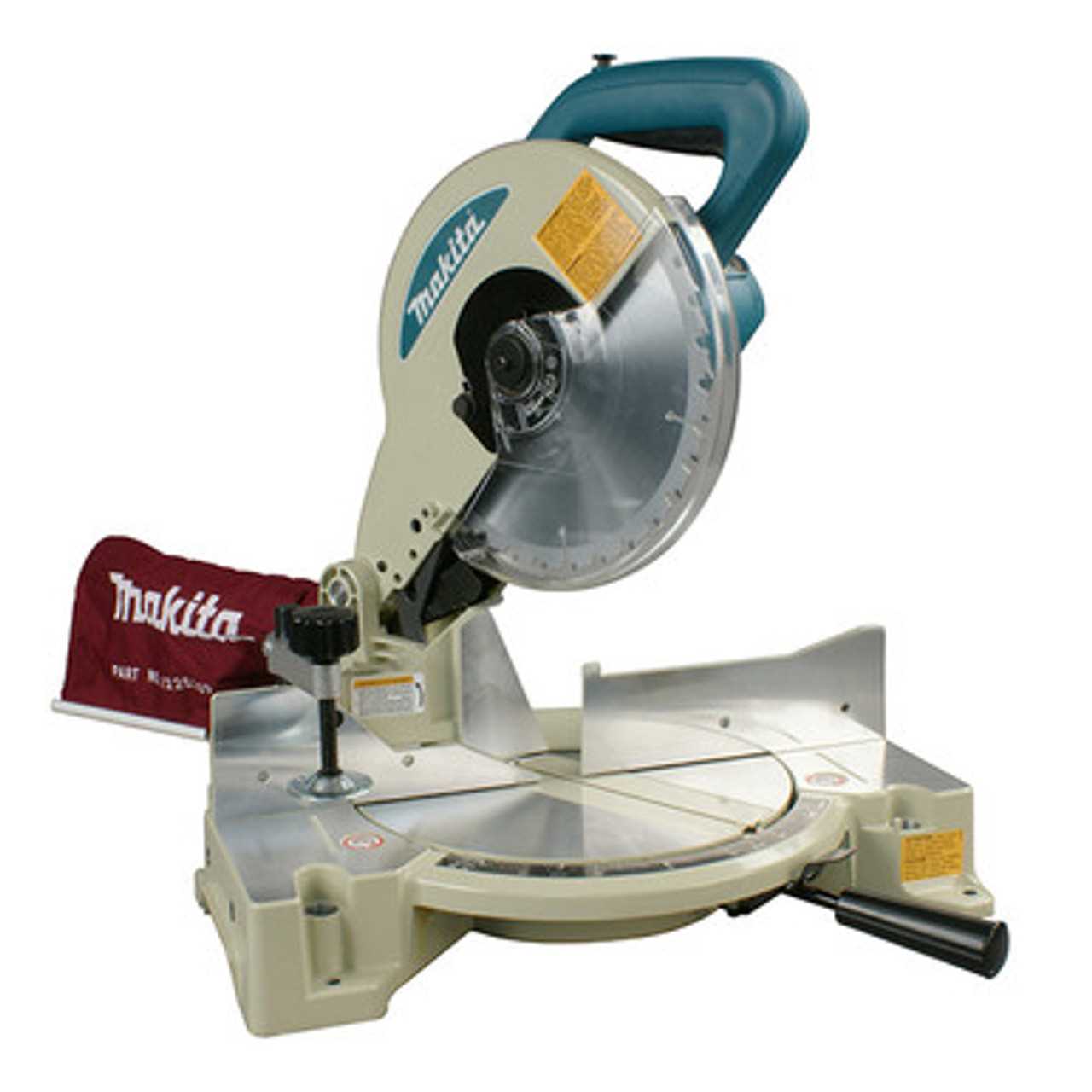
Key Components of the Makita LS1040
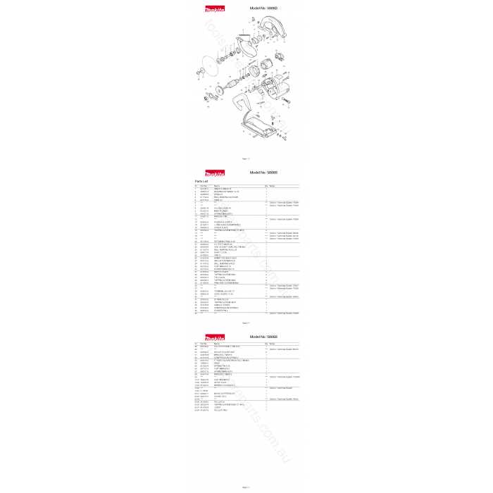
The functionality of this equipment relies on several essential elements that work together to ensure precision and efficiency during operation. Understanding these crucial parts allows users to maintain and optimize the tool for long-lasting performance.
Blade Mechanism: At the core of the tool’s cutting ability is the circular blade, which handles various materials with ease. Its sharpness and rotation speed directly affect the quality of cuts, making regular maintenance important.
Cutting Table: The sturdy platform where materials are positioned plays a vital role in stability. It supports the workpiece and allows for secure and accurate cutting operations.
Angle Adjustment Feature: Precision cutting is further enhanced by an adjustable angle system, enabling users to make cuts at different degrees. This flexibility is key for tackling a range of tasks.
Handle and Safety Lock: Ergonomic design ensures a comfortable grip, while the safety lock prevents accidental operation, making the tool safer to
Exploring the Saw Blade Mechanism
The circular saw blade system is a crucial component in ensuring accurate and smooth cuts during operation. By understanding how the mechanism functions, users can achieve greater precision and safety while working with the tool. This section will delve into the intricate design and operation of the blade’s movement, focusing on the pivotal elements that contribute to its efficiency.
Blade Mounting and Rotation
The blade is mounted onto a central hub, which allows it to rotate at high speeds. This rotational motion is driven by a motor that ensures steady and consistent cutting power. The secure attachment of the blade prevents wobbling, which could otherwise result in imprecise cuts.
Adjusting the Cutting Depth
One of the essential features of the saw is its ability to adjust the depth of the cut. This is achieved by manipulating the blade’s position in relation to the workpiece. Proper adjustment ensures that the blade engages the material at the correct angle and depth, allowing for clean, professional results
Understanding the Safety Features
When operating any power tool, understanding its built-in protective mechanisms is essential for ensuring safe and efficient usage. These features are designed to minimize risks and enhance user control during operation, making it crucial to be aware of how they function and contribute to overall safety.
Blade Guard Mechanism
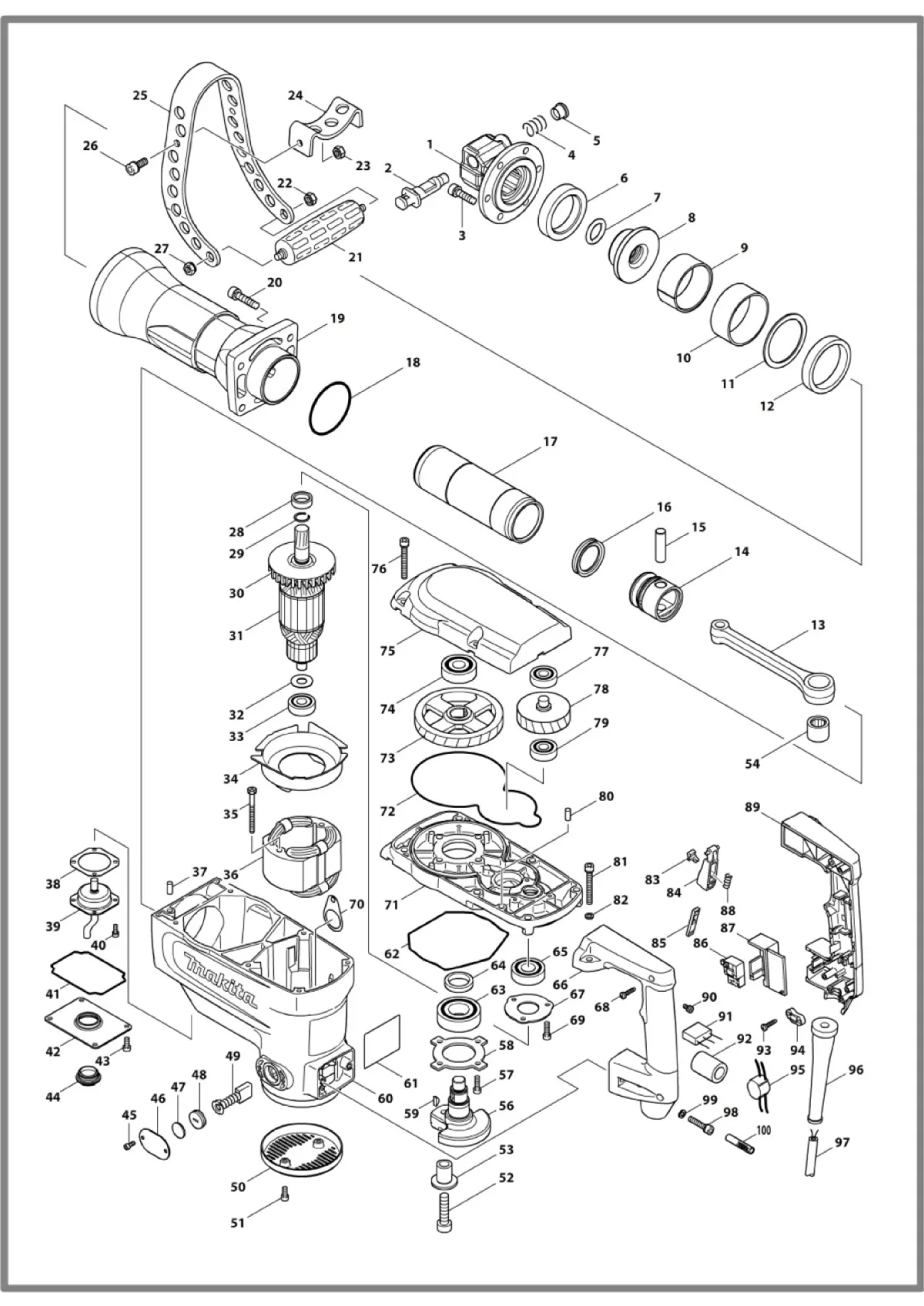
The blade guard is one of the most important components in protecting the user from accidental contact with the cutting edge. It automatically retracts as the tool is engaged and returns to its position after use, providing a layer of defense during operation.
Locking Mechanisms
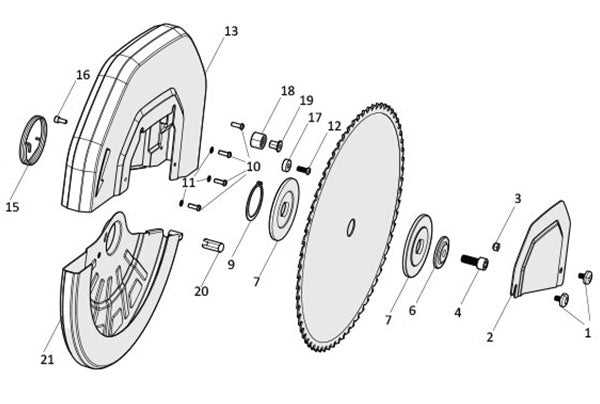
Various locking mechanisms ensure that moving parts remain securely in place while in use. This prevents unintended movements, which could lead to accidents, allowing for more precise and safer handling of the equipment.
Adjusting the Angle Settings
Proper angle adjustments are crucial for achieving precise cuts and ensuring the tool functions optimally. By carefully setting the desired angles, you can enhance the accuracy of your work while maintaining safety.
To adjust the angles, follow these steps:
- Ensure the device is powered off and unplugged before making any adjustments.
- Loosen the angle lock handle located on the base.
- Gently rotate the cutting unit to the desired angle, using the markings as a guide.
- Once the correct angle is set, securely tighten the lock handle to hold the position in place.
- Check the angle gauge to verify the accuracy of your settings.
For bevel adjustments, use the following procedure:
- Release the bevel lock located on the
Guide to the Motor Assembly

The motor assembly is a critical component in power tools, ensuring smooth operation and optimal performance. Understanding its structure and how the different elements work together can help in identifying issues and maintaining the tool’s efficiency over time.
Key Components of the Motor Assembly include several interconnected parts that work in harmony to generate and control the movement. These elements contribute to the proper functioning and are designed to handle various operational demands.
Maintenance of the motor assembly is crucial for prolonging the life of the tool. Regular checks and proper care ensure that all parts remain in good working order, reducing the risk of malfunction or breakdowns.
Inspecting the Base and Frame
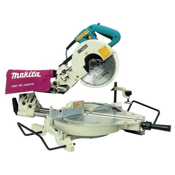
When evaluating the stability and performance of any cutting tool, it is essential to thoroughly examine its foundational components. The base and frame play a crucial role in ensuring precise cuts and overall operational efficiency. Regular inspections can help identify any wear or damage that might affect functionality.
Identifying Common Issues
Common problems that may arise in the base and frame include cracks, warping, or misalignment. Inspecting for these issues is vital, as they can lead to inaccuracies in cutting. Pay attention to any visible signs of damage, as well as the overall integrity of the structure.
Maintenance Tips
To maintain the longevity of these components, it is advisable to keep them clean and free from debris. Regularly lubricating joints and moving parts will also contribute to smoother operation. If any defects are found, timely repairs or replacements should be considered to ensure optimal performance.
Maintenance of Dust Collection System
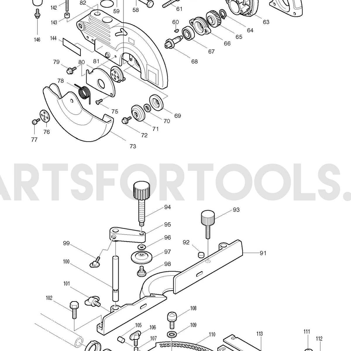
Ensuring the efficiency of the dust collection mechanism is essential for optimal performance and safety during operation. Regular upkeep not only enhances the functionality of the system but also contributes to a healthier working environment by minimizing airborne particles and debris.
Regular Cleaning: Periodic cleaning of the dust collection components is crucial. Dust and debris can accumulate, leading to blockages that reduce airflow and efficiency. Make it a habit to inspect and clean the filters, hoses, and collection bags frequently.
Inspect for Wear: Routine inspections for signs of wear and tear on all parts of the dust collection system can prevent unexpected failures. Check for cracks, holes, or other damage that may compromise performance. Replacing worn components promptly ensures consistent operation.
Maintain Seals and Connections: Proper sealing and tight connections are vital to prevent leaks that can diminish suction power. Regularly examine joints and seals, tightening or replacing them as necessary to maintain effective dust capture.
Monitor Performance: Keeping an eye on the system’s performance can help identify potential issues early. If you notice a decrease in suction power or an increase in dust escape, it may indicate a problem that needs addressing.
Professional Servicing: For comprehensive maintenance, consider enlisting professional services. Experts can perform detailed checks and repairs that may be beyond the scope of regular maintenance, ensuring the longevity and effectiveness of the dust collection system.
Replacing the Switch and Electrical Parts
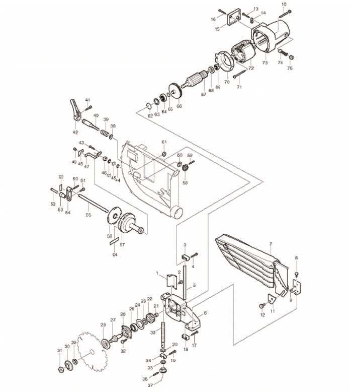
In any power tool, ensuring optimal functionality often requires attention to its electrical components. This section focuses on the process of replacing the switch and associated electrical elements, which are crucial for the tool’s operation. By following the appropriate steps, users can effectively restore performance and enhance safety.
Before beginning the replacement, it is essential to disconnect the tool from the power source. This precaution prevents any accidental activation during the process. Next, carefully remove the outer casing to access the internal components. Take note of the wiring connections, as they must be replicated accurately when installing the new switch.
When selecting a replacement switch, ensure compatibility with the specific model. After obtaining the new part, remove the old switch by detaching it from its mount and disconnecting the wires. Install the new switch by connecting the wires as per the noted configuration and securing it in place. Once everything is reassembled, conduct a thorough check to confirm that all parts are functioning correctly.
Safety is paramount, so if any uncertainties arise during the replacement process, consult a professional technician. Proper handling and installation of electrical components not only extend the lifespan of the tool but also ensure safe operation for the user.
Handle and Control System Overview
The handle and control system of a power tool is essential for its operation, ensuring user comfort and safety during use. This mechanism integrates various components designed to facilitate precise manipulation and effective performance, providing a seamless interaction between the user and the equipment.
Typically, the handle is ergonomically designed to minimize fatigue and enhance grip, allowing for extended usage without discomfort. The control system, including switches and levers, is strategically positioned for easy access, enabling quick adjustments while maintaining focus on the task at hand.
In addition to user-friendly features, this system often includes safety measures such as trigger locks or emergency shut-off functions, which help prevent accidental activation. Understanding the intricacies of this system can lead to improved handling and operational efficiency, ultimately enhancing the overall experience with the tool.
Identifying Common Wear Parts
Understanding the components that experience regular wear is essential for maintaining the longevity and efficiency of your equipment. These parts often require replacement to ensure optimal performance and to prevent potential failures during operation.
Common elements that may show signs of wear include:
- Blades: Regularly inspect for dullness or damage, as they significantly impact cutting efficiency.
- Drive belts: Check for cracks or fraying, which can lead to slippage and reduced power transmission.
- Bearings: Listen for unusual noises or vibrations that could indicate wear and necessitate replacement.
- Filters: Clean or replace air and oil filters to ensure proper airflow and lubrication.
- Brushes: Monitor carbon brushes for wear, as they are critical for maintaining electrical contact in motors.
Regular maintenance and timely replacement of these components will enhance performance and extend the lifespan of your tools. Always refer to the manufacturer’s recommendations for specific maintenance intervals and part specifications.
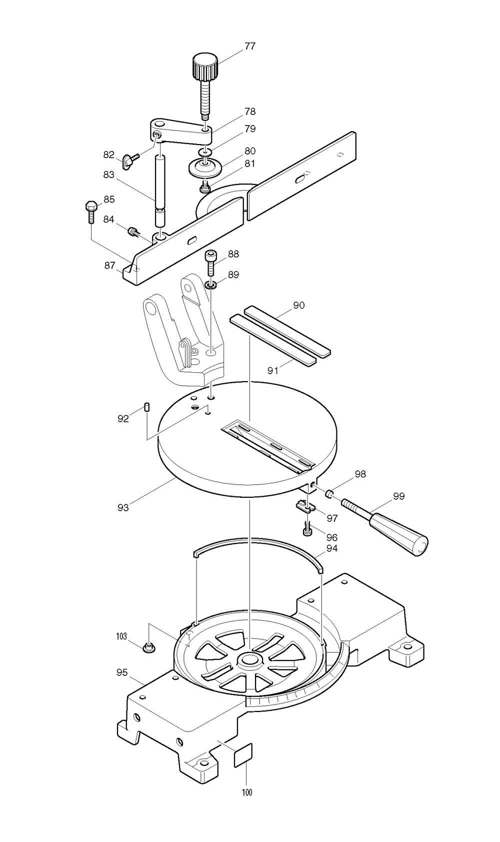
Assembly of Fence and Guard
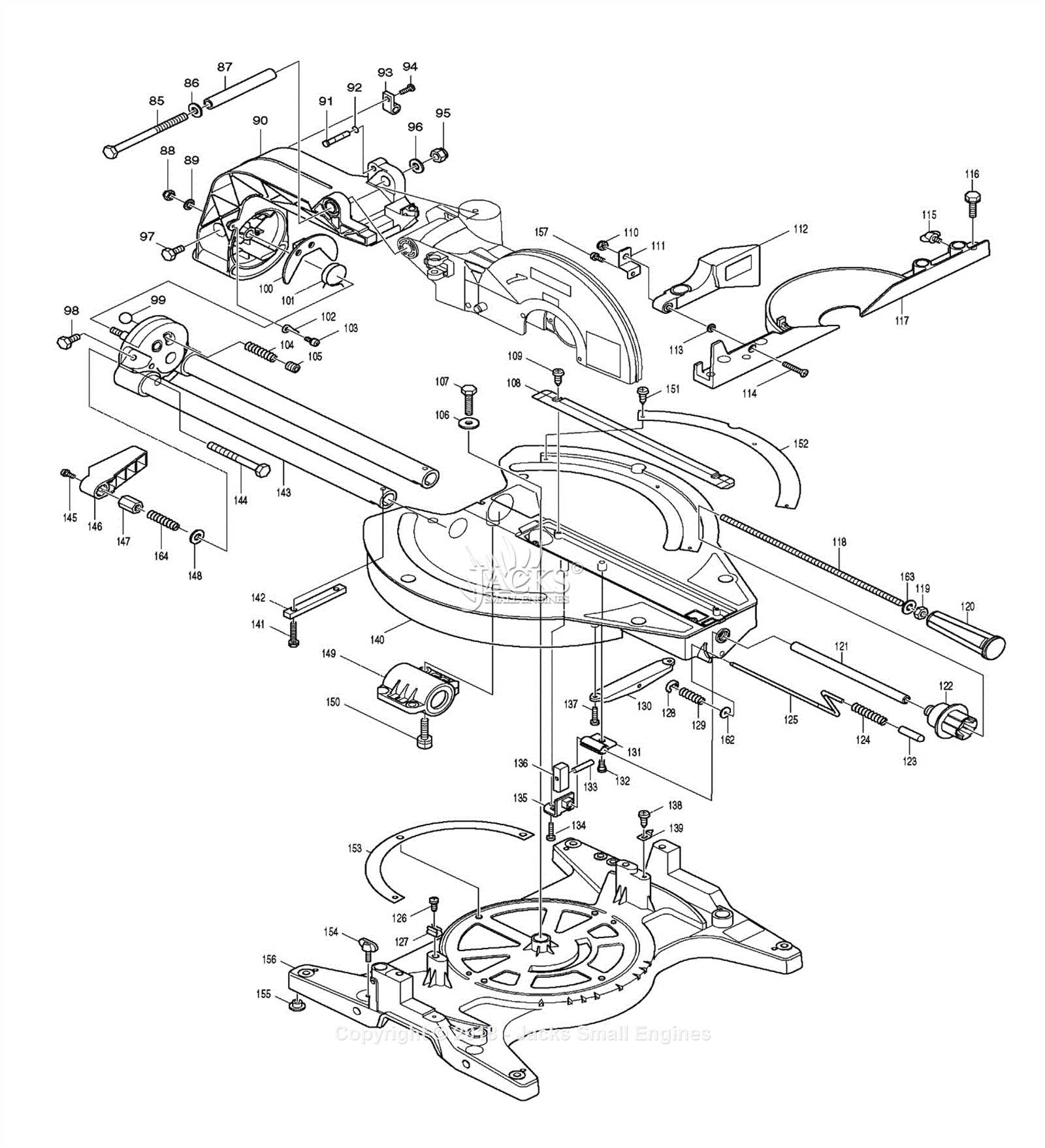
Proper installation of the fence and guard is crucial for ensuring safety and precision during operations. This section provides a detailed overview of the assembly process, emphasizing the significance of each component and its role in the overall functionality of the tool.
To successfully assemble the fence and guard, follow these steps:
- Gather all necessary components, including the fence, guard, and fasteners.
- Identify the mounting points on the base of the tool where the fence and guard will be attached.
- Align the fence with the mounting points, ensuring it is positioned correctly for accurate measurements.
- Secure the fence using the provided fasteners, making sure it is firmly in place.
- Attach the guard, aligning it with the designated slots to ensure proper coverage during operation.
- Check that both the fence and guard are securely fastened and functioning correctly.
Regular maintenance of these components is recommended to maintain optimal performance. Ensure that any adjustments needed for alignment are made promptly to enhance safety and efficiency during use.
Troubleshooting Power Issues
Power-related complications can arise in various equipment, often leading to performance interruptions. Identifying the root cause of these issues is crucial for restoring functionality. This section aims to provide insights into common power-related challenges and their potential solutions.
Begin by checking the power source to ensure it is functioning correctly. Inspect connections, cords, and outlets for any signs of wear or damage. A faulty power supply can significantly impact the device’s performance.
Next, examine the internal components. Accumulated dust and debris can obstruct electrical connections. Regular maintenance can prevent these blockages and ensure efficient operation.
Issue Possible Cause Solution No Power Defective power cord Replace the power cord Intermittent Power Loose connections Tighten all connections Device Overheating Clogged vents Clean the ventilation openings Sudden Shutdown Overload protection activated Reduce load and allow cooling In conclusion, regular inspections and maintenance are essential in preventing power-related issues. By taking proactive measures, users can ensure their equipment operates smoothly and efficiently.
Tips for Blade Alignment and Sharpening
Proper alignment and sharpening of cutting tools are crucial for achieving optimal performance and ensuring safety during operation. These essential maintenance tasks enhance the efficiency of the tool and prolong its lifespan, making it vital for users to master these techniques.
Alignment: To ensure that the blade is correctly aligned, start by checking the distance between the blade and the guide. Use a ruler or caliper for precision. Adjust the blade position as needed, ensuring it runs parallel to the cutting surface. This alignment minimizes wear and helps prevent binding during use.
Sharpening: Regularly sharpening the blade is necessary for maintaining its cutting ability. Use a sharpening stone or a file designed for the material of the blade. Apply even pressure while sharpening, maintaining the original angle of the blade edge. Test the sharpness by cutting through a small piece of wood; a sharp blade should make clean, effortless cuts.
By following these tips for alignment and sharpening, users can enhance their cutting tool’s efficiency, ensuring it remains in optimal working condition for a longer period.