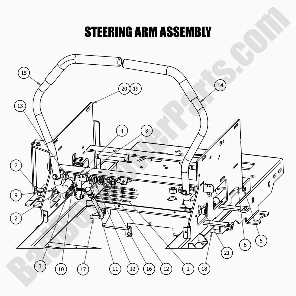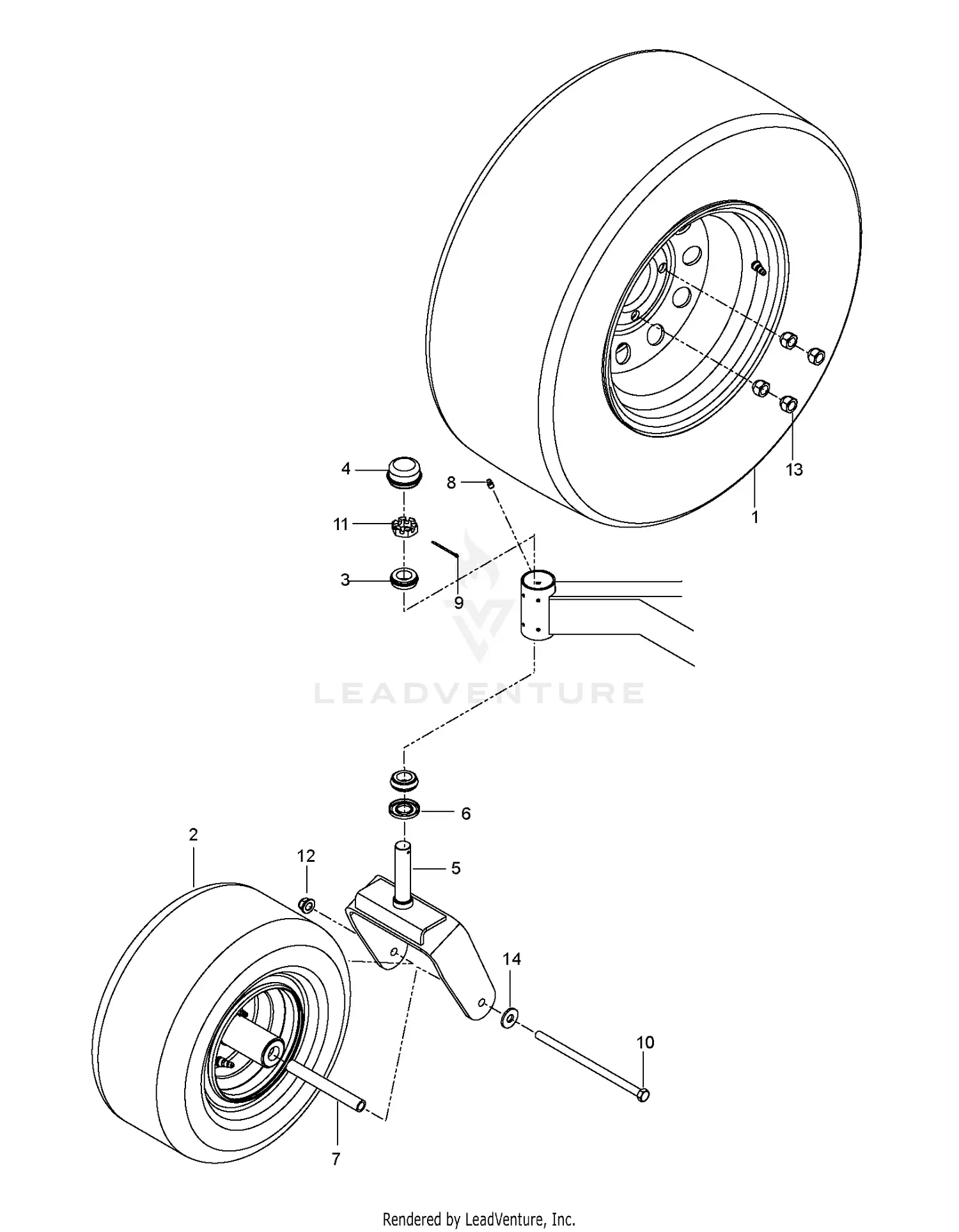
The MZ 54 model is recognized for its durable construction and efficient performance. When discussing its structure, understanding the individual elements that contribute to its overall functionality is crucial. This section offers a detailed look into the various segments that make up the MZ 54, highlighting their role in maintaining optimal operation.
Each unit within the MZ 54 system plays a vital role in ensuring the smooth functioning of the entire machine. By analyzing the key components, users can gain valuable insights into how the system works and how to address potential issues.
Whether you are looking to maintain or repair the MZ 54, having a clear understanding of its main elements will help ensure long-term efficiency. The following section provides a closer examination of these crucial elements, ensuring you can easily identify and work with them.
Understanding the Structure of Mz 54 Mower

The Mz 54 mower is built on a foundation of key mechanical elements that work together to ensure optimal performance. Its construction includes various interconnected components designed for seamless operation, each contributing to the efficiency and durability of the machine. By familiarizing yourself with the overall setup, you can gain a clearer picture of how the mower functions and what makes it reliable for various lawn care tasks.
Key Components Overview
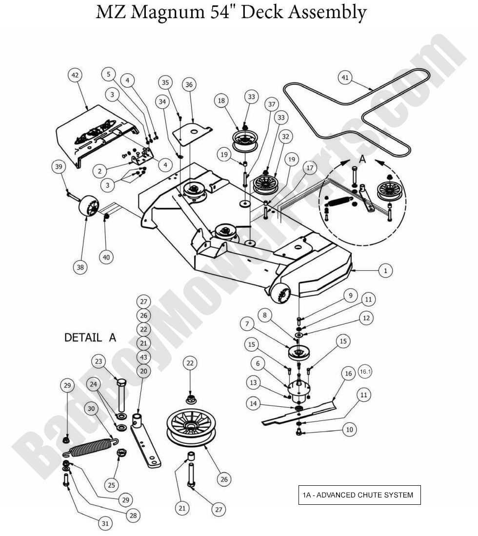
At the core of the Mz 54 mower’s structure are several essential systems. These include the cutting assembly, propulsion system, and control mechanisms. Each system plays a vital role in delivering smooth cutting and maneuverability, making the mower both user-friendly and effective for different terrains.
Main Mechanical Systems
The mower’s primary systems are designed to work in harmony, providing precision and power during operation. From the cutting blades to the drive mechanism, every element is carefully engineered for long-lasting performance, ensuring that the mower remains efficient across varying conditions.
| Component | Function |
|---|
| Maintenance Activity | Frequency | Description |
|---|---|---|
| Visual Inspection | Monthly | Check for visible wear and tear on the components. |
| Lubrication | Every 3 months | Apply appropriate lubricant to moving parts to reduce friction. |
| Functional Test | Quarterly | Ensure the mechanism operates smoothly without obstruction. |
Locating the Drive System Components
The drive system is a critical element of machinery, comprising various interconnected elements that ensure optimal functionality. Identifying these components is essential for effective maintenance and troubleshooting. Understanding their arrangement and role can significantly enhance the performance of the equipment.
Identifying Key Elements
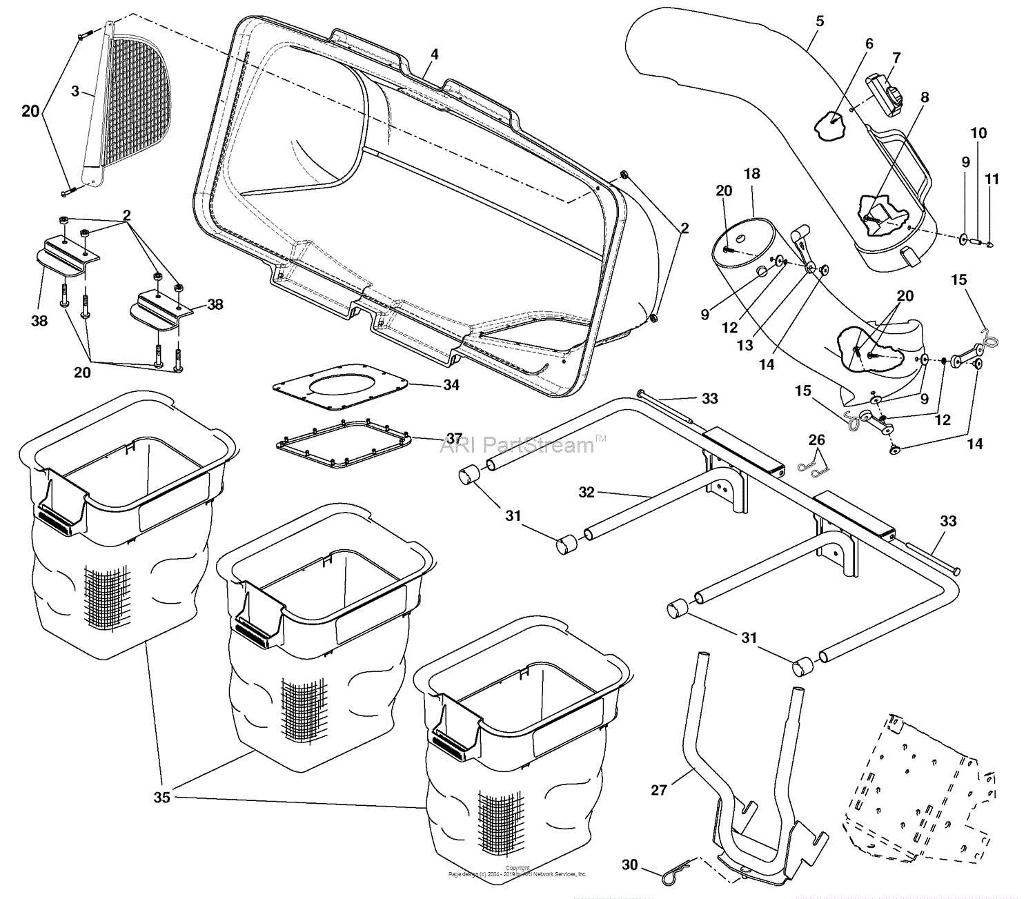
To begin with, it is important to recognize the major elements that comprise the drive mechanism. These typically include the motor, transmission, and related components that work in unison to deliver power. Familiarity with each element’s function can aid in diagnosing issues and implementing necessary adjustments.
Accessing the Drive Assembly
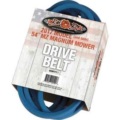
Gaining access to the drive assembly is crucial for inspection and repairs. It often involves removing protective covers and ensuring safety protocols are followed. Once accessed, one can clearly see how each element is positioned and connected, facilitating easier identification and analysis.
Mz 54 Safety Features and Components
The Mz 54 model incorporates various safety mechanisms designed to ensure the well-being of its users. These essential features play a crucial role in enhancing operational security and minimizing risks during use.
One significant aspect of safety in the Mz 54 is its advanced braking system, which offers reliable stopping power under various conditions. This system includes features that prevent accidental activation, ensuring that the equipment remains under control at all times.
Additionally, the Mz 54 is equipped with protective casings that shield critical elements from external damage. This design not only enhances durability but also reduces the likelihood of malfunctions that could compromise safety.
Another notable component is the user-friendly interface, which provides clear indicators and warnings. These visual cues help operators make informed decisions, promoting safe operation and reducing the chances of errors.
In summary, the Mz 54 integrates multiple safety elements that collectively contribute to a secure and efficient user experience. Understanding these components is essential for maximizing the potential of the equipment while ensuring safety standards are upheld.
Electrical Parts in Mz 54 Mower
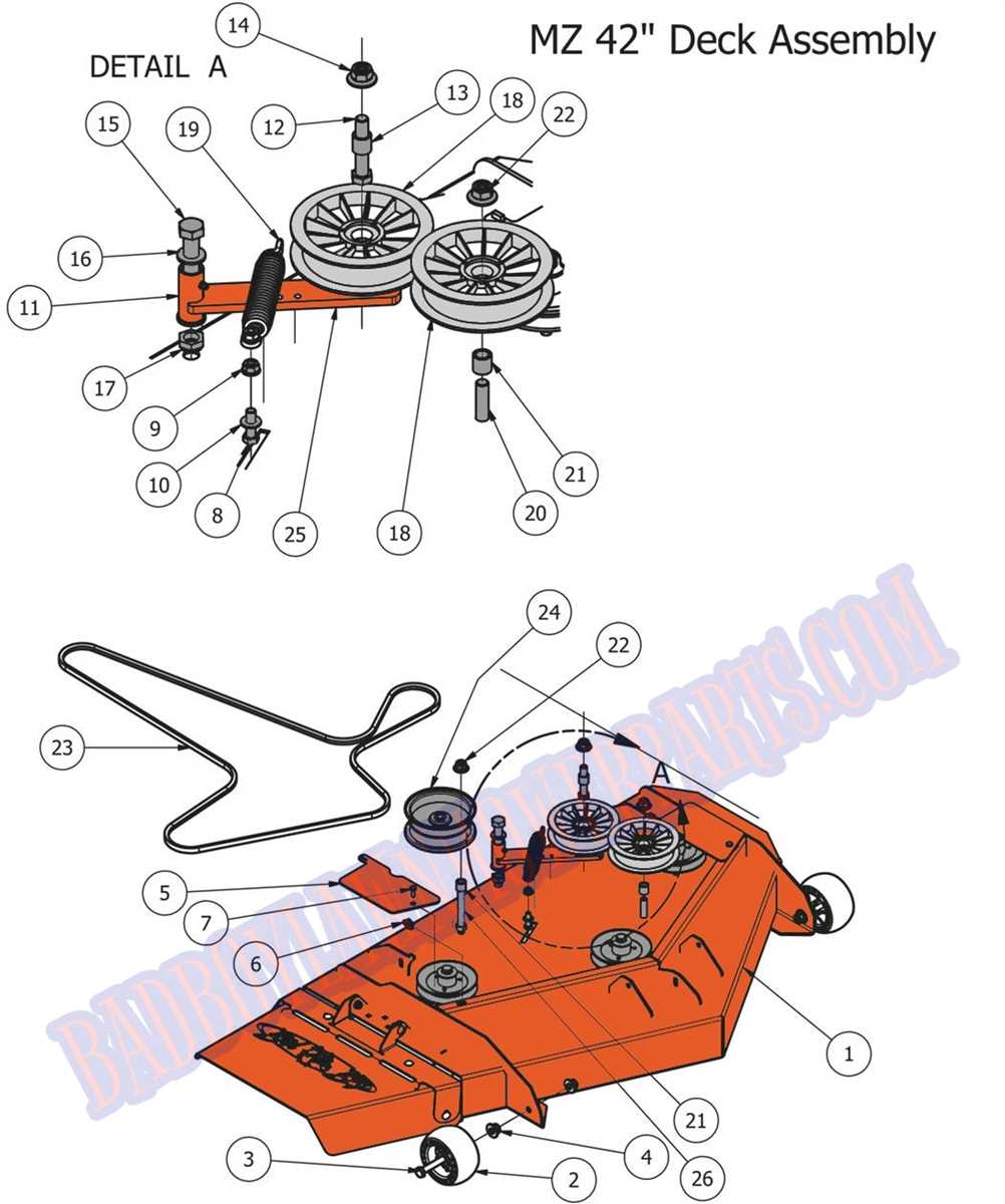
The electrical components in the Mz 54 mower play a crucial role in ensuring its efficient operation. These elements work together to facilitate the mower’s functionality, providing power and control necessary for effective cutting and maintenance of the lawn.
Understanding these components can help users troubleshoot issues and maintain their equipment effectively. Below is a table outlining key electrical elements commonly found in the Mz 54 mower, including their functions and specifications.
| Component | Function | Specifications |
|---|---|---|
| Battery | Stores electrical energy to power the mower. | 12V, 20Ah |
| Starter Motor | Engages the engine for ignition. | 12V, 1.5 kW |
| Ignition Coil | Transforms low voltage to high voltage for spark generation. | Primary: 12V, Secondary: 20kV |
| Switch | Controls the electrical circuit to start or stop the mower. | SPST (Single Pole Single Throw) |
| Wiring Harness | Connects various electrical components and ensures proper signal flow. | Various gauges, insulated |
Mz 54 Deck Assembly Details
The assembly of the Mz 54 deck is crucial for ensuring optimal performance and stability. Each component plays a vital role in the overall functionality, contributing to a well-balanced and efficient operation.
Key Components: The primary elements involved in the deck structure include the frame, support brackets, and fastening mechanisms. These components work in unison to provide strength and durability.
Assembly Process: To achieve a successful assembly, it is essential to follow a systematic approach. Begin by aligning the frame correctly, ensuring that all brackets fit snugly. The use of appropriate fasteners will guarantee a secure attachment.
Maintenance Tips: Regular checks on the integrity of the deck assembly are recommended. Inspect for wear and tear on the components, and replace any damaged parts to maintain functionality.
Troubleshooting with Mz 54 Parts Diagram
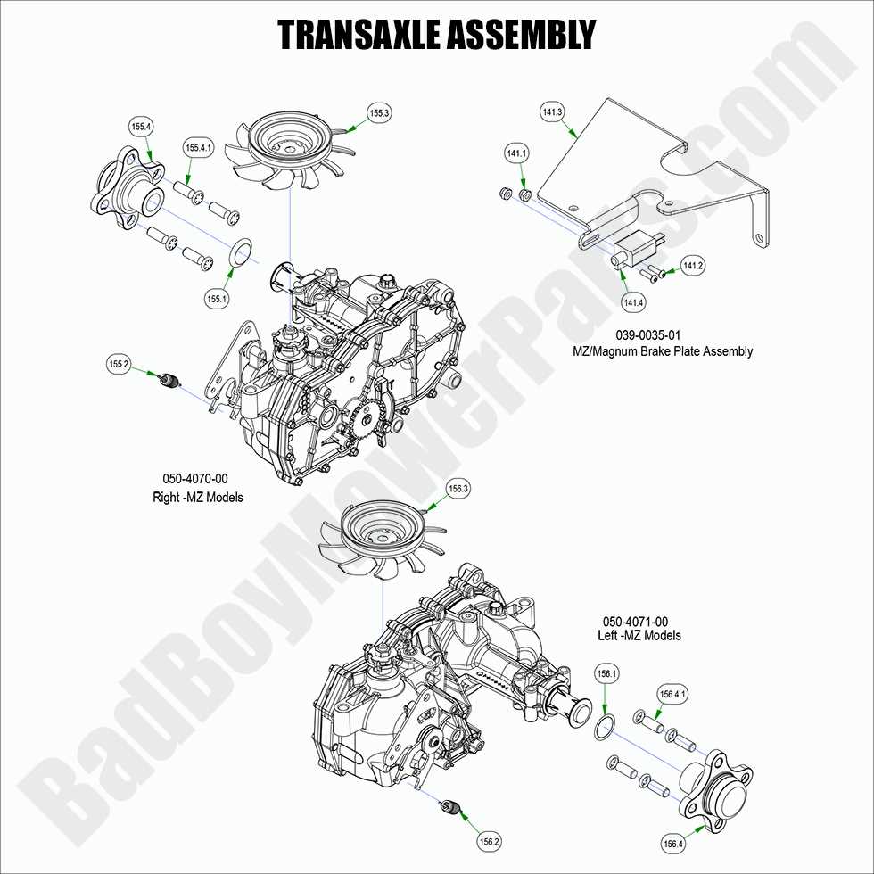
Understanding the components of the Mz 54 model can significantly aid in identifying and resolving common issues. By familiarizing oneself with the various elements, users can more effectively pinpoint problems and implement appropriate solutions.
When faced with challenges, consider the following steps:
- Identify the Symptoms: Begin by observing the behavior of the equipment. Take note of any unusual sounds, movements, or performance issues.
- Reference Component Locations: Use a visual guide to locate specific elements associated with the identified symptoms. This reference can assist in understanding the layout and function of each component.
- Check for Wear and Damage: Inspect the identified parts for signs of wear, damage, or misalignment. Pay special attention to connections and mechanical linkages.
- Consult the Manual: Review the operational manual for troubleshooting tips related to the observed issues. It often contains valuable information regarding common failures and remedies.
- Test and Replace if Necessary: After identifying the problematic components, conduct tests to confirm their functionality. If a part is found to be defective, proceed with replacement.
By following these guidelines, users can systematically approach troubleshooting and enhance the performance of their Mz 54 equipment.
