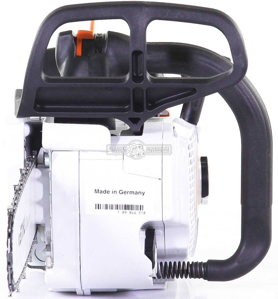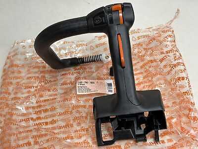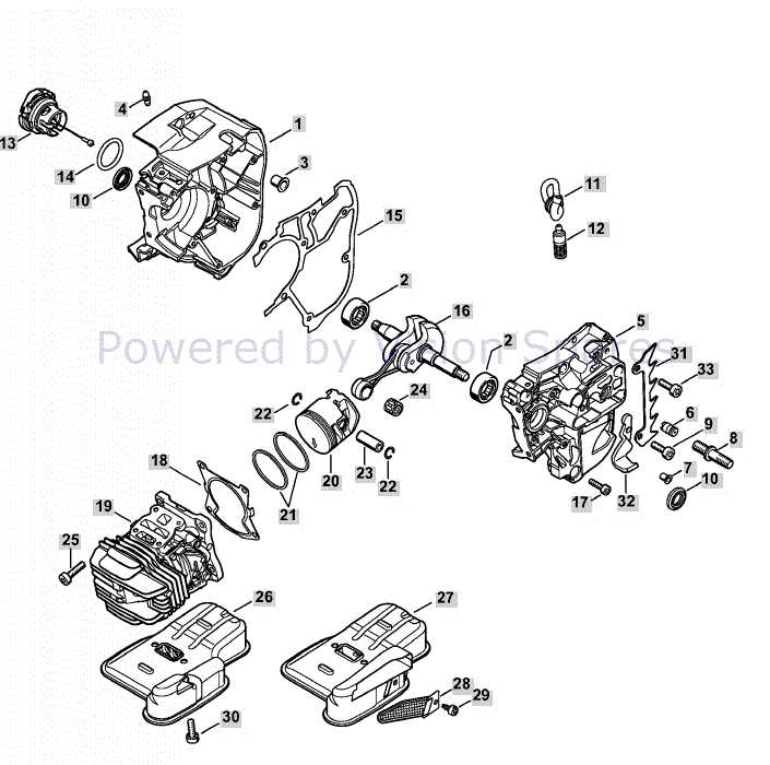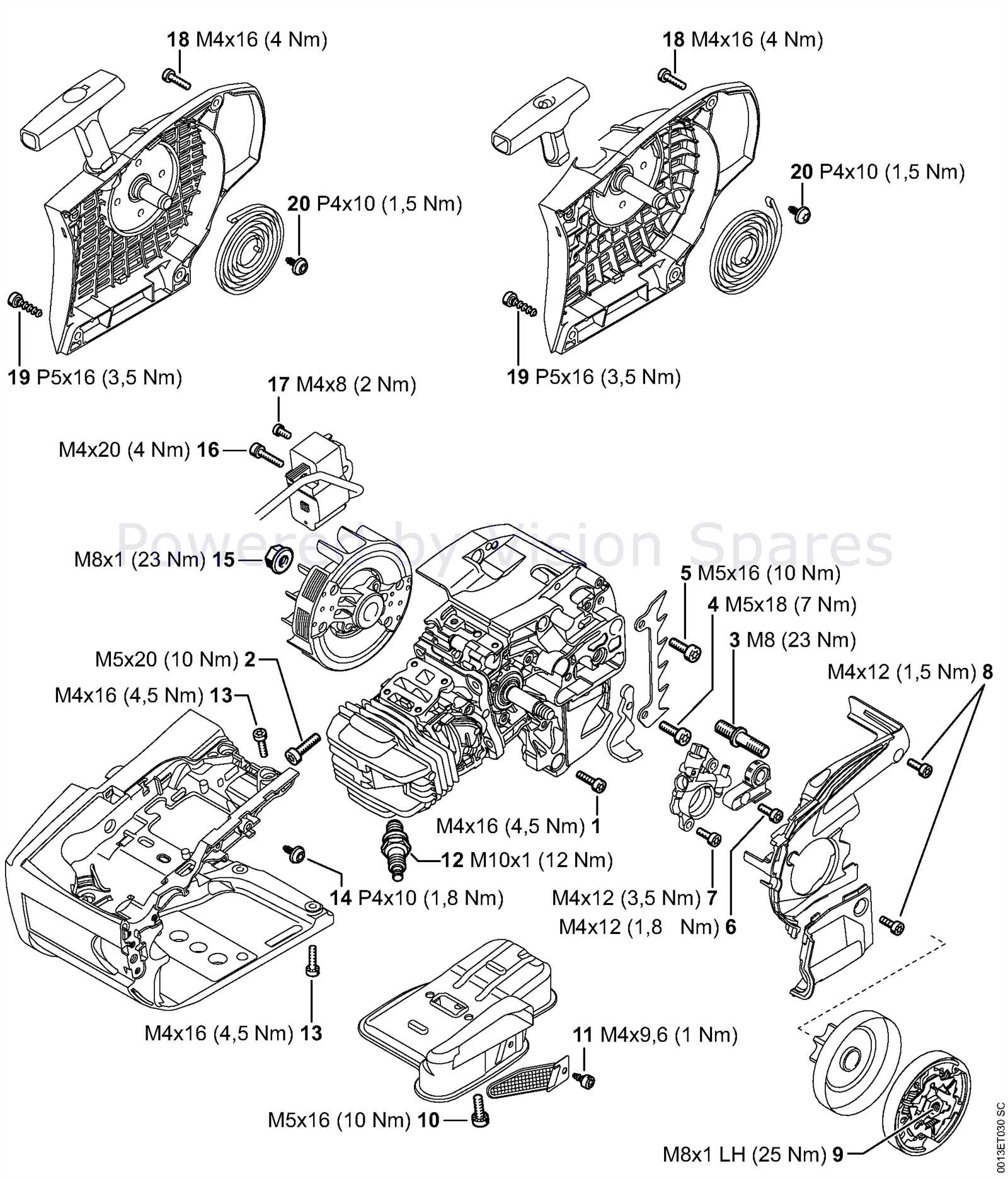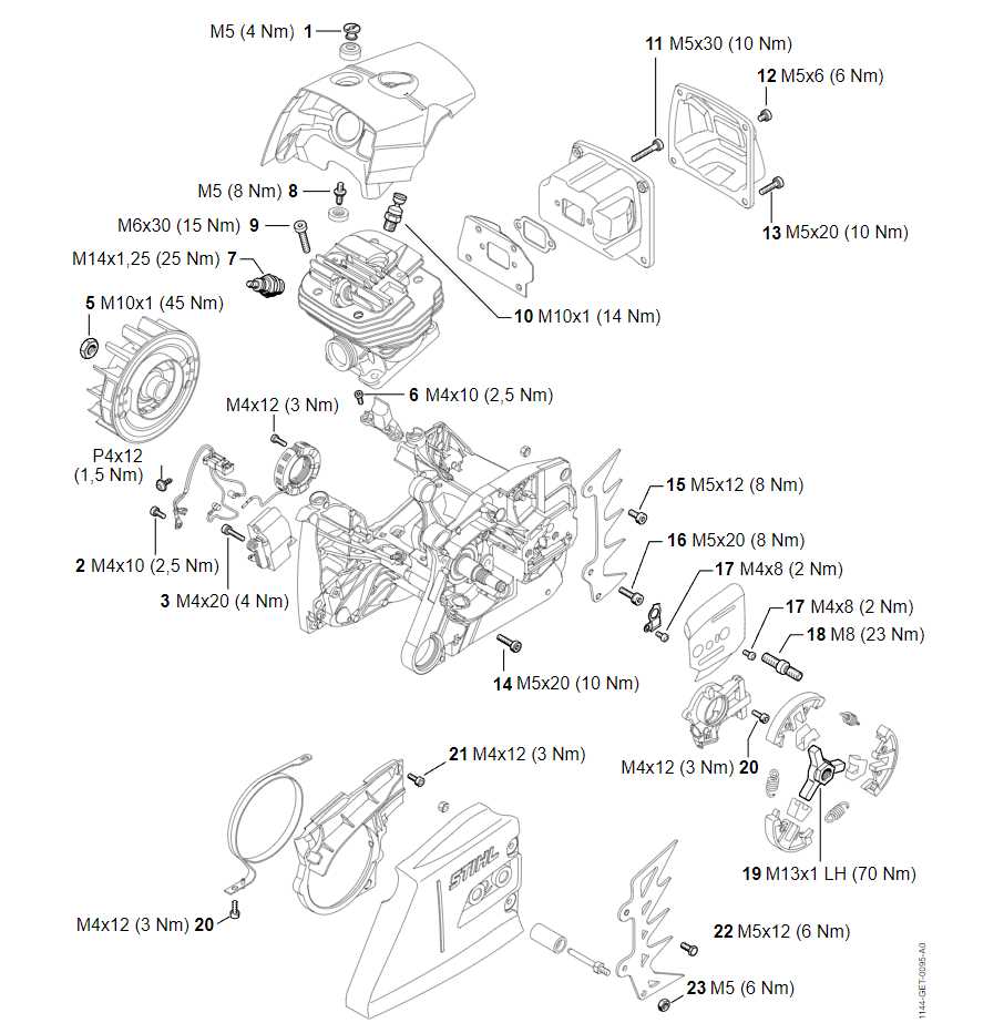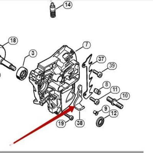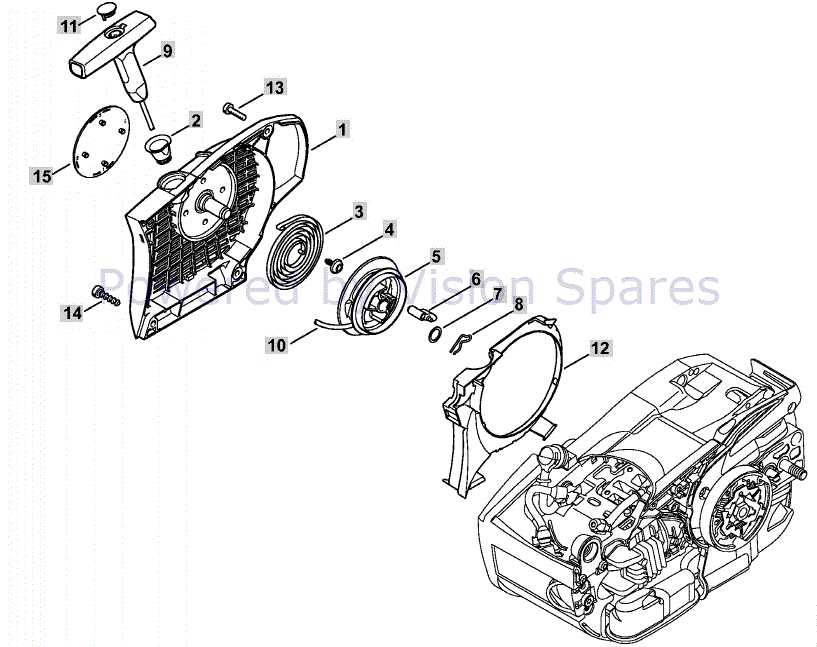
The intricate design of the MS 201 TC showcases a harmonious blend of technology and engineering, essential for its optimal performance. Recognizing the individual elements within this system can significantly enhance one’s ability to maintain and troubleshoot effectively. Each component plays a vital role, contributing to the overall functionality and efficiency of the machine.
For users and enthusiasts alike, a comprehensive exploration of the various elements is invaluable. By familiarizing oneself with the arrangement and characteristics of these components, individuals can ensure better care and longevity of their equipment. This knowledge not only facilitates easier repairs but also empowers users to make informed decisions regarding maintenance practices.
Delving into the specifics of these integral components reveals their distinct functions and interconnections. Whether for routine upkeep or troubleshooting unexpected issues, understanding how each piece interacts with others can lead to a more seamless and productive experience with the MS 201 TC.
Overview of MS 201 TC Components
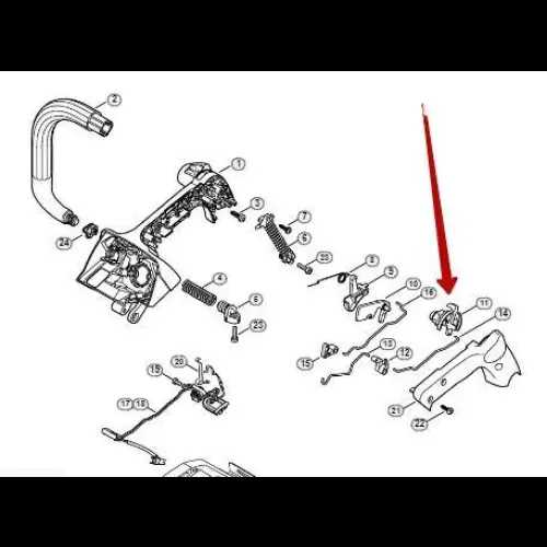
The MS 201 TC is a finely engineered tool designed for efficiency and reliability. Understanding its various elements is essential for optimal performance and maintenance. Each component plays a vital role in ensuring the functionality and durability of the equipment, contributing to its overall effectiveness in the field.
This section outlines the key features of the MS 201 TC, highlighting the significance of each part in the operational process.
| Component Name | Description |
|---|---|
| Engine | The heart of the tool, providing the necessary power for operation. |
| Guide Bar | A crucial element that guides the chain during cutting tasks. |
| Chain | The cutting mechanism that interacts with the material being processed. |
| Air Filter | Protects the engine by preventing dirt and debris from entering. |
| Fuel Tank | Stores the fuel needed for engine operation, ensuring longevity and performance. |
| Handle | Provides control and maneuverability, enhancing user experience. |
| Safety Features | Includes mechanisms designed to protect the user during operation. |
Importance of Parts Diagrams
Visual representations of components are crucial for understanding the structure and functionality of complex machines. They serve as a reference point, enabling users to identify individual elements, their arrangement, and how they interact within the overall system. This clarity aids in maintenance, repairs, and the efficient assembly of equipment.
Enhanced Understanding
These visual aids facilitate a deeper comprehension of mechanical systems by breaking down intricate designs into manageable segments. Users can easily navigate through the various elements, making it simpler to recognize each piece’s role. This understanding is vital for troubleshooting and optimizing performance.
Efficient Repairs and Maintenance
Having access to detailed illustrations allows technicians to pinpoint issues swiftly, minimizing downtime. With clear depictions, repairs can be conducted with precision, ensuring that each component is correctly addressed. This efficiency not only saves time but also reduces the risk of further complications during maintenance tasks.
Key Features of MS 201 TC
The MS 201 TC model stands out in its category due to a combination of advanced engineering and practical functionality. Designed for efficiency, this device incorporates various innovative elements that enhance user experience and overall performance.
- Lightweight Design: Crafted with a focus on portability, the device allows for ease of handling during extended use.
- Powerful Engine: The unit is equipped with a robust motor, providing substantial cutting power for various applications.
- Ergonomic Grip: Features a comfortable handle that minimizes fatigue, making it suitable for prolonged operation.
- Fuel Efficiency: Designed to optimize fuel consumption, ensuring longer operational time between refuels.
- Low Emission Technology: Incorporates environmentally friendly technology, reducing harmful emissions during operation.
Overall, the MS 201 TC exemplifies a blend of durability and user-centric design, making it a reliable choice for both professionals and hobbyists.
How to Interpret Diagrams
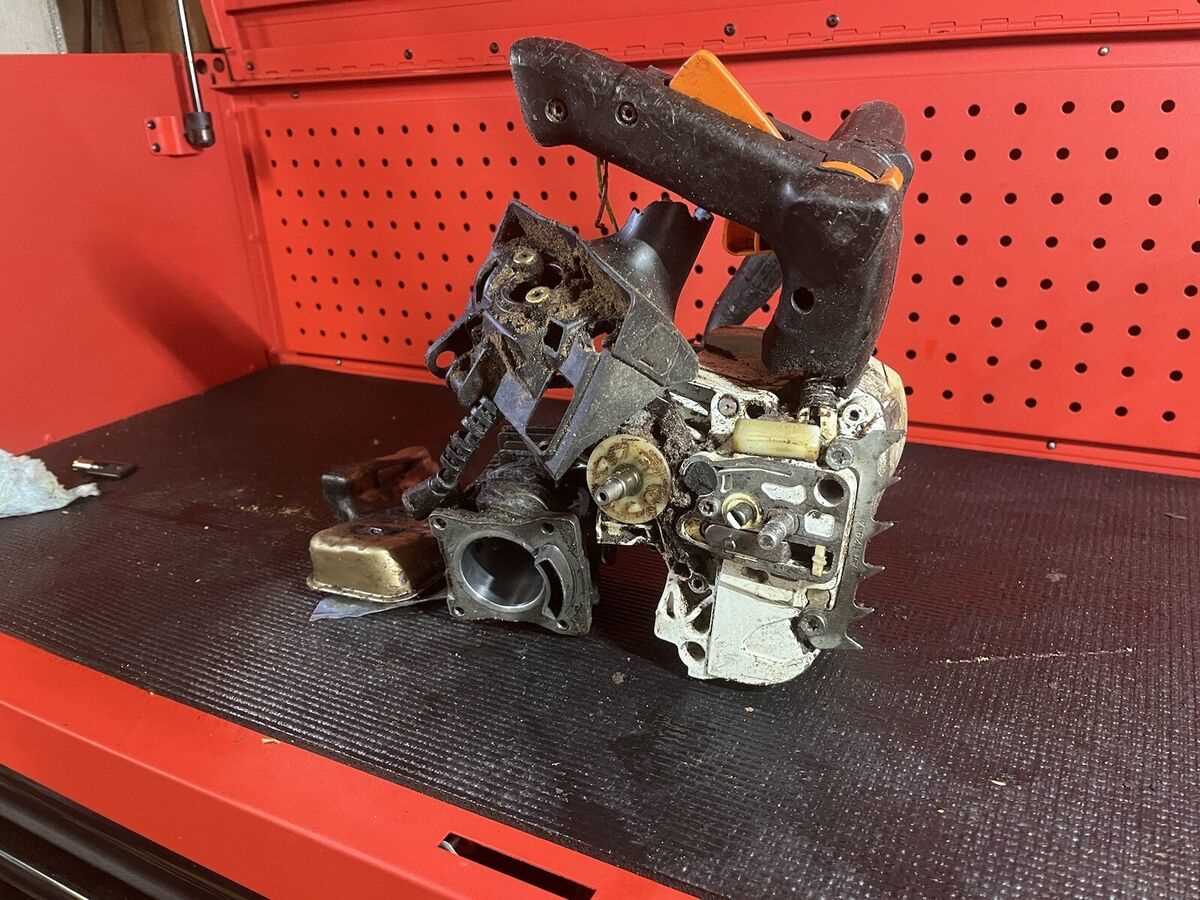
Understanding technical illustrations can significantly enhance your ability to assemble or maintain complex equipment. These visual representations are designed to provide clarity on how components fit together or interact, allowing you to troubleshoot issues or perform repairs effectively.
Key Elements of Technical Illustrations
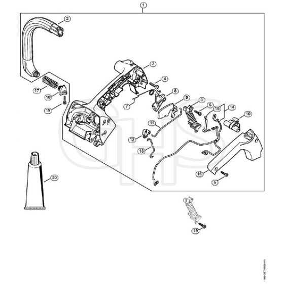
Technical drawings often contain symbols, lines, and labels that represent different aspects of machinery. It is important to familiarize yourself with the common conventions used in these images, such as line types that indicate movement, section views, or hidden components. By grasping these fundamentals, you’ll be able to quickly identify essential details.
Practical Steps for Interpretation
When examining a technical drawing, follow a systematic approach. Begin by reviewing any legends or keys provided, as these will explain the meaning of symbols or line styles used. Next, look at the overall structure to understand the relationships between various components. Focus on the sequence of connections or alignments to avoid misinterpretations.
| Symbol | Meaning |
|---|
| Safety Measure | Description | |||||||||||||||
|---|---|---|---|---|---|---|---|---|---|---|---|---|---|---|---|---|
| Personal Protective Equipment (PPE) | Wear appropriate gloves, goggles, and footwear to protect yourself from potential hazards. | |||||||||||||||
| Power Disconnection | Ensure the equipment is completely powered off and disconnected from any energy sources before beginning work. | |||||||||||||||
| Tool Inspection | Regularly check the condition of your tools to ensure they are safe and in proper working order. | |||||||||||||||
| Clear Work Area | Keep the area clean and free of obstacles that could cause tripping or other accidents. | |||||||||||||||
Foll
Troubleshooting Common IssuesWhen using equipment for demanding tasks, it is common to encounter occasional malfunctions or performance issues. Understanding these problems and knowing how to address them effectively can minimize downtime and prevent further damage. This guide outlines practical solutions for frequent operational difficulties and provides tips to maintain your machine in optimal condition. Engine Fails to StartIf the engine doesn’t start, the issue could be related to fuel supply or ignition components. Begin by checking the fuel level and ensuring there is no blockage in the fuel lines. Inspect the spark plug for wear or damage, and replace it if necessary. Ensure that the choke is properly engaged, especially in cold weather conditions. Reduced Cutting EfficiencyA common challenge is a noticeable decline in cutting performance. This can be due to dull or damaged blades. Regularly sharpen or replace blades to maintain peak efficiency. Also, check for debris build-up around the cutting area, which can hinder smooth operation. Ensuring that all components are properly lubricated can also improve functionality. Benefits of Using Original Parts
When maintaining or repairing equipment, it is crucial to ensure the highest level of performance and durability. Opting for authentic components from the manufacturer offers several key advantages that can enhance the longevity and reliability of your machinery. Precision Fit and Functionality: Original replacements are specifically designed to match the exact specifications of your machine. This ensures seamless integration, minimizing potential issues that could arise from using incompatible alternatives. Enhanced Durability: Genuine components are built to last, as they undergo rigorous testing and quality control. This translates to improved resilience under demanding conditions, reducing the frequency of replacements and repairs. Manufacturer Support: By choosing authentic replacements, you retain the full backing of the manufacturer’s warranty and support network. This gives you peace of mind, knowing that your equipment is protected and serviced by professionals with in-depth knowledge of the product. In conclusion, selecting genuine components guarantees optimal performance, longer service life, and comprehensive support, making it the smartest choice for keeping your equipment running smoothly. Upgrades and Enhancements AvailableThere are various modifications and performance improvements that can be applied to increase the efficiency and durability of your tool. These enhancements allow users to tailor their equipment to meet specific needs, whether for better precision, ease of use, or extending its lifespan in challenging environments.
|
