When maintaining or repairing a tool, it is essential to have a clear understanding of the key elements involved in its construction. Knowing the location and purpose of each part helps ensure that every adjustment or replacement is done correctly, ultimately extending the lifespan of the machine. A breakdown of the system provides a comprehensive view, making the maintenance process more straightforward and efficient.
For those looking to keep their equipment in optimal condition, it’s vital to familiarize oneself with the layout and structure. Each component has a specific function, and understanding how these elements work together can prevent costly mistakes. This guide offers clarity and insight into the intricate workings of the tool’s design, making sure users are well-prepared for any necessary repairs or upgrades.
Component Overview and Layout
The machinery under discussion is composed of several essential elements, each contributing to its overall functionality. Understanding the arrangement and role of these elements is key to ensuring smooth operation and maintenance.
Key Mechanical Elements
The central components include the engine unit, control systems, and structural supports, all working together to deliver efficient performance. The layout is designed for easy access to vital areas, allowing for quick adjustments and servicing.
Internal Structure and Connectivity
The internal framework integrates various systems to ensure optimal power transmission. Strong connections between moving parts enhance durability, while clear pathways for lubrication and cooling maintain the equipment’s longevity.
Detailed Breakdown of Ms230 Engine Components
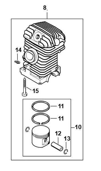
The internal structure of this machine’s motor is a complex assembly of various interconnected elements. Each of these elements plays a vital role in ensuring the smooth operation of the engine, contributing to its overall performance and durability. Understanding the function of each component allows for easier maintenance and troubleshooting.
Cylinder forms the core, where combustion takes place, driving the piston. The piston, in turn, transfers energy through a series of mechanisms, including the connecting rod and crankshaft, ensuring the rotation needed for operation.
Other key elements include the carburetor, which regulates the air-fuel mixture, and the ignition system, which triggers the combustion process. Each piece is finely tuned, ensuring that the engine works efficiently under varying conditions.
Understanding the Fuel System Assembly
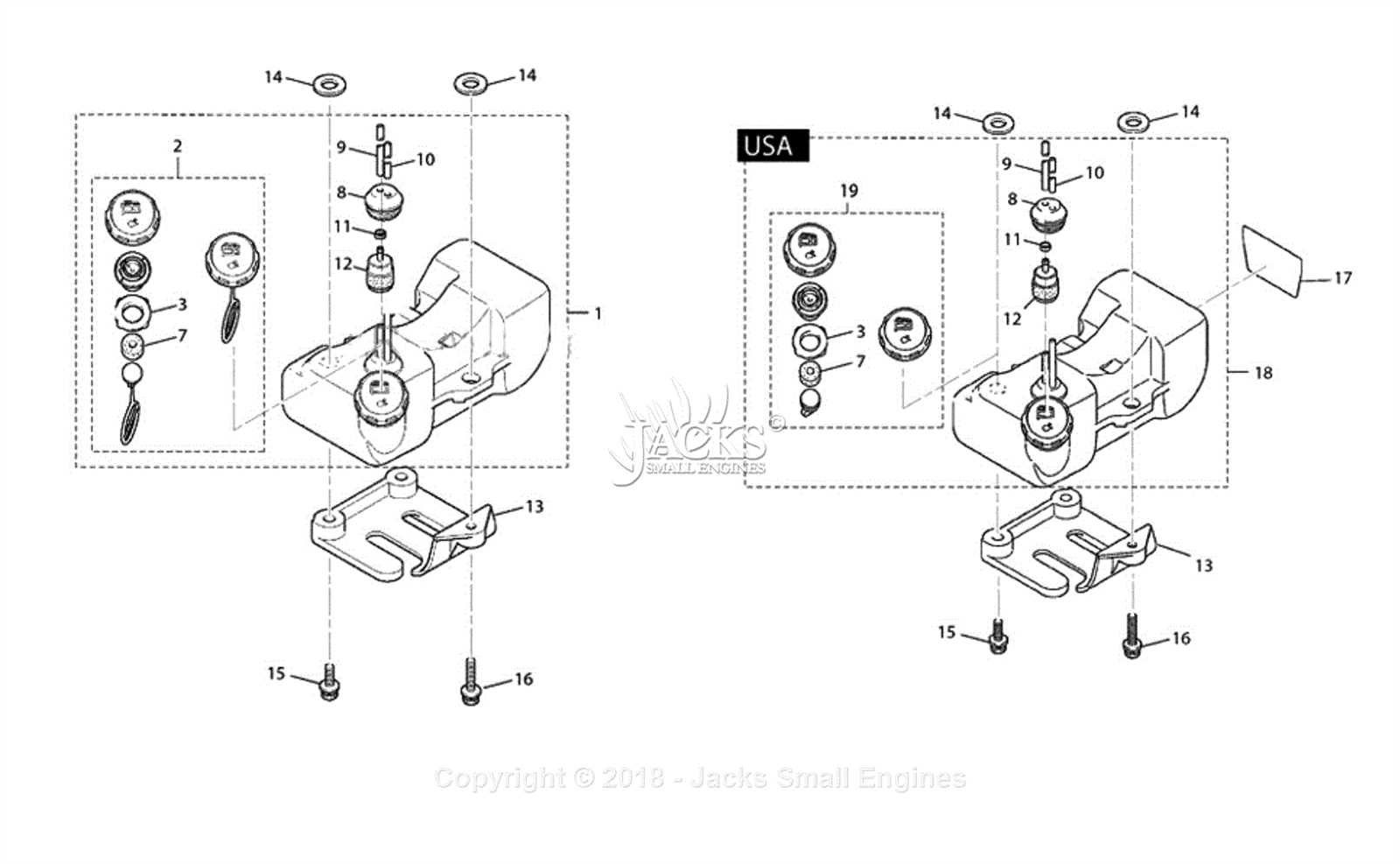
The fuel system is a crucial component responsible for providing the engine with the necessary energy to function efficiently. By carefully delivering fuel to the engine, this system ensures optimal performance, power, and longevity. Understanding how the various elements of this system work together can help in maintaining its effectiveness and preventing potential malfunctions.
The system consists of several interconnected components that manage the flow of fuel from the tank to the engine. These parts collaborate to regulate pressure, control fuel distribution, and maintain the right mixture for efficient combustion. Knowing how each part operates and interacts can aid in troubleshooting issues and performing routine maintenance.
Exploring the Ignition System Components
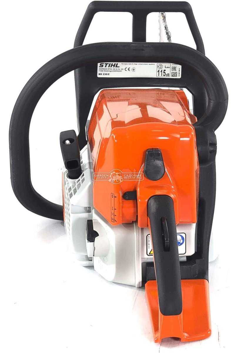
The ignition system plays a crucial role in ensuring efficient engine performance. It consists of various elements that work together to generate the necessary spark for combustion, providing smooth operation and reliability. Understanding how these components interact helps in maintaining the engine and diagnosing issues effectively.
Key Elements of the System
The ignition system includes several vital elements responsible for producing and controlling the spark. These components are designed to work seamlessly, ensuring that fuel ignition occurs at the correct moment for optimal engine function.
Overview of Each Component
| Component | Function |
|---|---|
| Spark Plug | Produces the spark that ignites the fuel-air mixture in the engine cylinder. |
| Ignition Coil | Transforms the low-voltage from the battery into the high-voltage needed by the spark plug. |
| Flywheel | Generates electrical current through its interaction with magnets, aiding in spark creation. |
| Switches and Wiring | Ensure that electrical signals are sent and controlled throughout the system. |
Chain Tensioner Mechanism Explained
The chain tensioner is a critical component that ensures the optimal operation of the cutting system. Proper tension allows for efficient performance and prolongs the lifespan of the tool. This mechanism is designed to maintain the correct tension of the cutting chain, preventing issues like slippage or uneven cuts.
How It Works: The tensioner adjusts the position of the guide bar, which in turn alters the tightness of the chain. This adjustment is made through a screw-based system that tightens or loosens the chain depending on the direction of rotation. Ensuring the right amount of tension prevents excessive wear and enhances safety during operation.
Maintenance Tip: Regularly checking the tensioner mechanism is essential to prevent malfunctions. Over time, the system may require cleaning or minor adjustments to keep it functioning smoothly.
Ms230 Starter Assembly and Function
The starting mechanism is a crucial component in the functionality of any engine. It ensures the initial ignition and operation by providing the necessary force to start the combustion process. Understanding the assembly and working principles of this mechanism helps in maintenance and troubleshooting, ensuring optimal performance.
Components of the Starting Mechanism
The starting assembly consists of several key elements that work together harmoniously. Each part plays a significant role in facilitating a smooth start.
| Component | Function |
|---|---|
| Starter Handle | Used to manually engage the starting mechanism. |
| Spring | Stores energy to assist in the recoil process. |
| Pawl | Engages with the flywheel to initiate engine rotation. |
| Starter Cup | Houses the starter components and connects to the flywheel. |
Working Principle
When the starter handle is pulled, the spring is tensioned, storing energy. As the handle is released, the pawl engages with the flywheel, causing it to rotate. This rotation ignites the fuel-air mixture in the engine, allowing it to start. The design ensures a reliable and efficient starting process, vital for the overall performance of the machinery.
Carburetor Parts and Operation
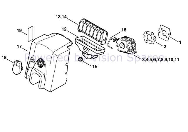
The carburetor is a vital component in many combustion engines, responsible for mixing air and fuel to create a combustible mixture. Understanding its construction and functionality is essential for efficient engine performance and maintenance. Various elements within the carburetor work together to ensure optimal operation and fuel efficiency.
Key Components
Among the essential elements are the float chamber, needle valve, and jets, each playing a crucial role in regulating fuel flow. The float chamber maintains a consistent fuel level, while the needle valve controls the fuel supply based on the engine’s demands. Jets determine the fuel-air ratio, influencing the engine’s performance under different conditions.
Operational Mechanism
When the engine is running, air enters the carburetor through the air intake, creating a vacuum that draws fuel from the float chamber. The mixture then travels into the engine cylinders, where it ignites, generating power. This process highlights the importance of each part working harmoniously to achieve efficient combustion.
Guide to Air Filter and Housing
The air filtration system plays a crucial role in maintaining optimal engine performance. It ensures that clean air enters the combustion chamber, which is essential for efficient operation. Understanding the components involved and their functions can help in proper maintenance and troubleshooting.
Understanding the Air Filter
The air filter is designed to capture dust, debris, and other contaminants from the air before it reaches the engine. A clean air filter promotes better fuel efficiency and prolongs the life of the engine. Here are some key aspects to consider:
- Function: Prevents harmful particles from entering the engine.
- Types: Available in various materials, including paper, foam, and cotton.
- Maintenance: Regular cleaning or replacement is necessary for optimal performance.
Air Filter Housing
The housing is the protective casing that holds the air filter in place. It ensures a secure fit and helps maintain proper airflow. Key points regarding the housing include:
- Design: Must allow sufficient air intake while preventing dust entry.
- Installation: Proper alignment and sealing are essential to avoid air leaks.
- Inspection: Regular checks for cracks or damage can prevent air intake issues.
Examining the Oil Pump System
The oil circulation mechanism plays a crucial role in ensuring optimal performance and longevity of mechanical systems. It is responsible for delivering lubricant to various components, reducing friction and preventing overheating. Understanding its operation is essential for maintaining efficiency and reliability.
The primary function of the lubrication apparatus involves drawing oil from the reservoir and directing it to critical areas requiring lubrication. This process is facilitated by the action of the pump, which generates the necessary pressure to circulate the fluid effectively. Regular inspection of this system can prevent potential failures and prolong the lifespan of machinery.
Additionally, components such as filters and hoses contribute to the overall efficiency of the lubrication network. Filters help to remove impurities, while hoses transport the oil to various points of need. Ensuring these parts are in good condition is vital for the uninterrupted operation of the entire lubrication system.
Muffler and Exhaust Setup
The exhaust system is crucial for optimizing engine performance and minimizing noise. Proper assembly and maintenance of the components are essential for efficient operation and longevity. This section focuses on the key elements of the muffler and exhaust configuration, ensuring effective emission management and sound control.
Components of the Exhaust System
- Muffler: Reduces noise produced by the engine.
- Exhaust Pipe: Directs harmful gases away from the engine.
- Mounting Brackets: Secure the muffler and pipes in place.
- Gaskets: Provide a seal between connections to prevent leaks.
Installation Steps
- Begin by ensuring all components are clean and free from debris.
- Attach the muffler to the exhaust pipe using appropriate gaskets.
- Secure the assembly with mounting brackets to prevent movement.
- Check for any leaks and ensure all connections are tight.
Clutch and Drive System Breakdown
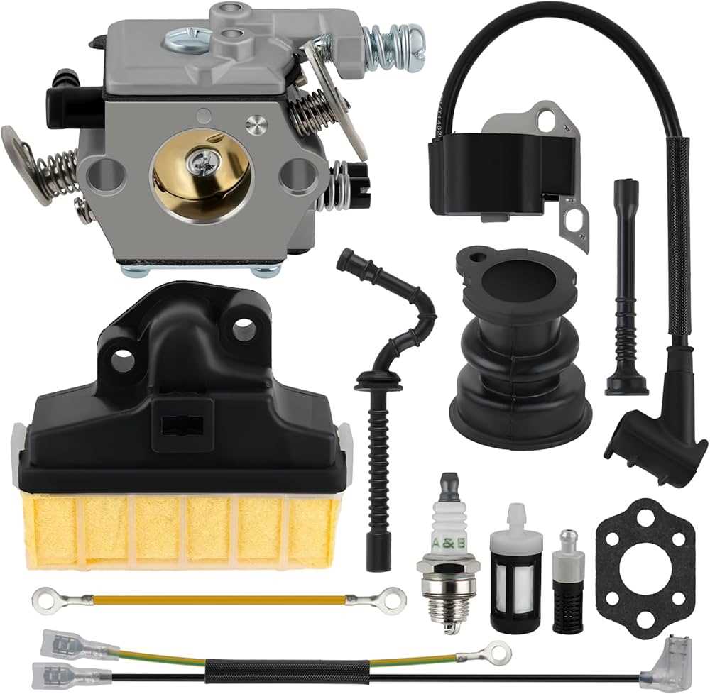
The clutch and drive assembly is essential for transmitting power efficiently from the engine to the operational components of the equipment. Understanding its function and components can enhance maintenance and troubleshooting efforts. This section will delve into the critical elements of the engagement and disengagement mechanism, focusing on how they interact to ensure smooth operation.
Clutch Mechanism: This component is responsible for connecting and disconnecting the engine’s power to the drivetrain. It comprises various parts such as the friction disc, pressure plate, and release bearing, each playing a vital role in the engagement process. When activated, the clutch allows for smooth acceleration and deceleration by modulating power delivery.
Drive System Components: The drive system includes elements such as the transmission, drive shafts, and pulleys. Each of these components works together to translate the engine’s rotational force into usable motion. Regular inspection and maintenance of these parts can prevent premature wear and ensure optimal performance during operation.
Common Issues: Problems within the clutch and drive assembly can manifest as slipping, unusual noises, or difficulty in engaging gears. Identifying these issues early can mitigate further damage and maintain the efficiency of the equipment. Regular checks and replacements of worn components are crucial for long-term reliability.
Recoil Starter Components Explained
The recoil starter system is an essential mechanism that facilitates the initiation of engine operation. Understanding its individual elements can help in diagnosing issues and performing effective maintenance. This section delves into the primary components involved in this assembly, offering insights into their functions and interactions.
| Component | Description |
|---|---|
| Starter Handle | The grip used to pull the starter cord, initiating the starting process. |
| Starter Cord | A strong, flexible line that connects the handle to the recoil spring, allowing for easy pulling. |
| Recoil Spring | This spring stores energy when the cord is pulled, enabling the return action once the handle is released. |
| Clutch Pawls | These are the small levers that engage with the flywheel, transferring energy to start the engine. |
| Flywheel | A heavy wheel that stores rotational energy, crucial for maintaining engine momentum during startup. |