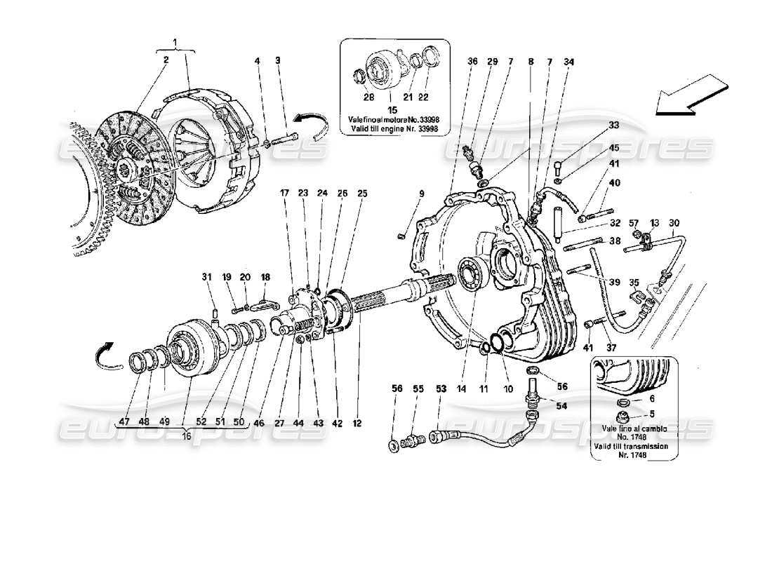
In the realm of machinery and equipment, comprehending the arrangement of individual elements is crucial for effective maintenance and troubleshooting. A visual representation of these components not only aids in identifying each part but also enhances the understanding of how they interact within the overall system. This knowledge empowers users to perform repairs, modifications, and optimizations with confidence.
Analyzing a structured layout allows technicians and engineers to pinpoint issues quickly and ascertain the proper functioning of various elements. By breaking down complex assemblies into manageable sections, one can achieve a clearer perspective on the mechanics at play. Such insights are invaluable for both seasoned professionals and newcomers to the field.
Moreover, having access to a well-organized illustration can significantly improve communication among team members. It serves as a common reference point, ensuring that everyone is on the same page when discussing specific features or troubleshooting steps. This collaborative approach fosters a deeper understanding and can lead to more efficient problem-solving.
Understanding the 026 Parts Diagram
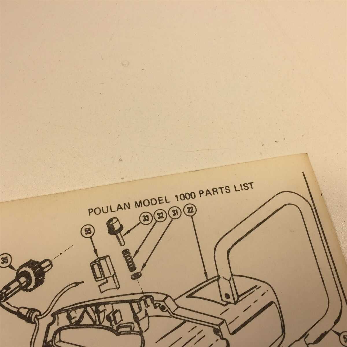
This section aims to enhance your comprehension of the intricate layout that showcases the various components of the equipment. By examining this visual representation, you can gain insights into how each piece interacts within the whole system.
- Identifying each element and its function
- Recognizing the relationships between different sections
- Understanding assembly and disassembly processes
By delving into these aspects, users can effectively troubleshoot issues and perform maintenance tasks, leading to optimal performance.
Key Components of the 026 Diagram
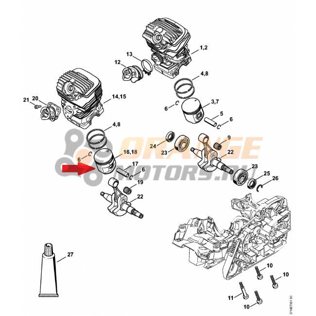
Understanding the fundamental elements of a technical layout is essential for effective analysis and maintenance. Each section plays a critical role, contributing to the overall functionality and efficiency of the system. By exploring these crucial components, one can gain valuable insights into the operation and assembly of the equipment.
1. Power Unit: This segment serves as the heart of the machinery, converting energy into operational force. It is vital to ensure its integrity for optimal performance.
2. Transmission Assembly: This area is responsible for transferring energy from the power source to various moving parts. Its design influences the overall efficiency and responsiveness of the system.
3. Control Mechanism: This component governs the operation of the machine, allowing users to adjust settings and respond to operational demands. A well-designed control unit enhances user experience and functionality.
4. Safety Features: Integral to any mechanical design, these elements provide protection for both the machine and its operator. Regular checks are essential to ensure these features are in place and functioning properly.
5. Structural Framework: This forms the foundation that supports all other elements. A robust and well-engineered structure ensures stability and durability under various operational conditions.
By familiarizing oneself with these key sections, individuals can better appreciate the complexities involved in the machinery’s design and operation, ultimately leading to more effective use and maintenance.
How to Read the 026 Parts Diagram
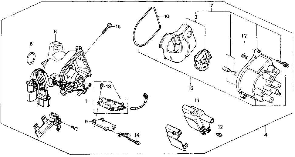
Understanding the intricate layout of components is crucial for effective assembly and maintenance. This guide aims to simplify the process of interpreting the visual representation of elements, enabling users to easily identify and work with each part.
Familiarizing with Symbols
Before diving into the specifics, it’s essential to recognize common symbols used in the illustration. These symbols provide vital information about each component’s function and connection.
- Shapes: Different shapes often indicate varying types of components, such as circular for fasteners and rectangular for housings.
- Lines: Solid lines typically represent direct connections, while dashed lines may indicate optional or alternative paths.
- Labels: Pay attention to labels and numbers associated with each component for easy reference.
Interpreting Layout and Relationships
Once familiar with the symbols, focus on the layout to understand how each part interacts within the system.
- Start with the overview: Examine the entire illustration to get a sense of the overall structure.
- Identify major components: Look for larger sections that house critical elements; these often serve as the backbone of the assembly.
- Trace connections: Follow the lines to see how components are linked, ensuring you understand the flow of operation.
- Refer to the key: Utilize any accompanying legend or key that provides additional context for symbols and connections.
By mastering these techniques, you’ll enhance your ability to work with the visual representation effectively, leading to more successful repairs and maintenance tasks.
Common Issues with 026 Components
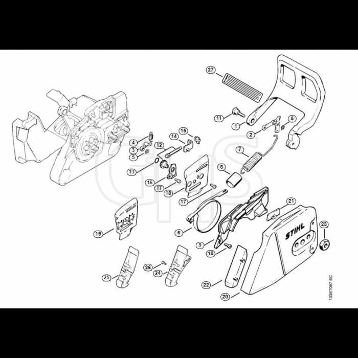
When working with specific machinery components, several recurring challenges may arise, impacting overall performance and efficiency. Identifying these issues early can help in implementing effective solutions and prolonging the lifespan of the equipment.
| Issue | Description | Potential Solutions |
|---|---|---|
| Wear and Tear | Components may degrade over time due to friction and environmental factors. | Regular maintenance and timely replacements are essential. |
| Misalignment | Improper alignment can lead to increased stress and failure. | Routine checks and adjustments can mitigate this issue. |
| Corrosion | Exposure to moisture can cause rust and deterioration. | Use of protective coatings and storing in dry conditions can help. |
| Overheating | Excessive heat can damage sensitive components. | Ensure proper ventilation and monitor operational temperatures. |
Maintenance Tips for 026 Parts
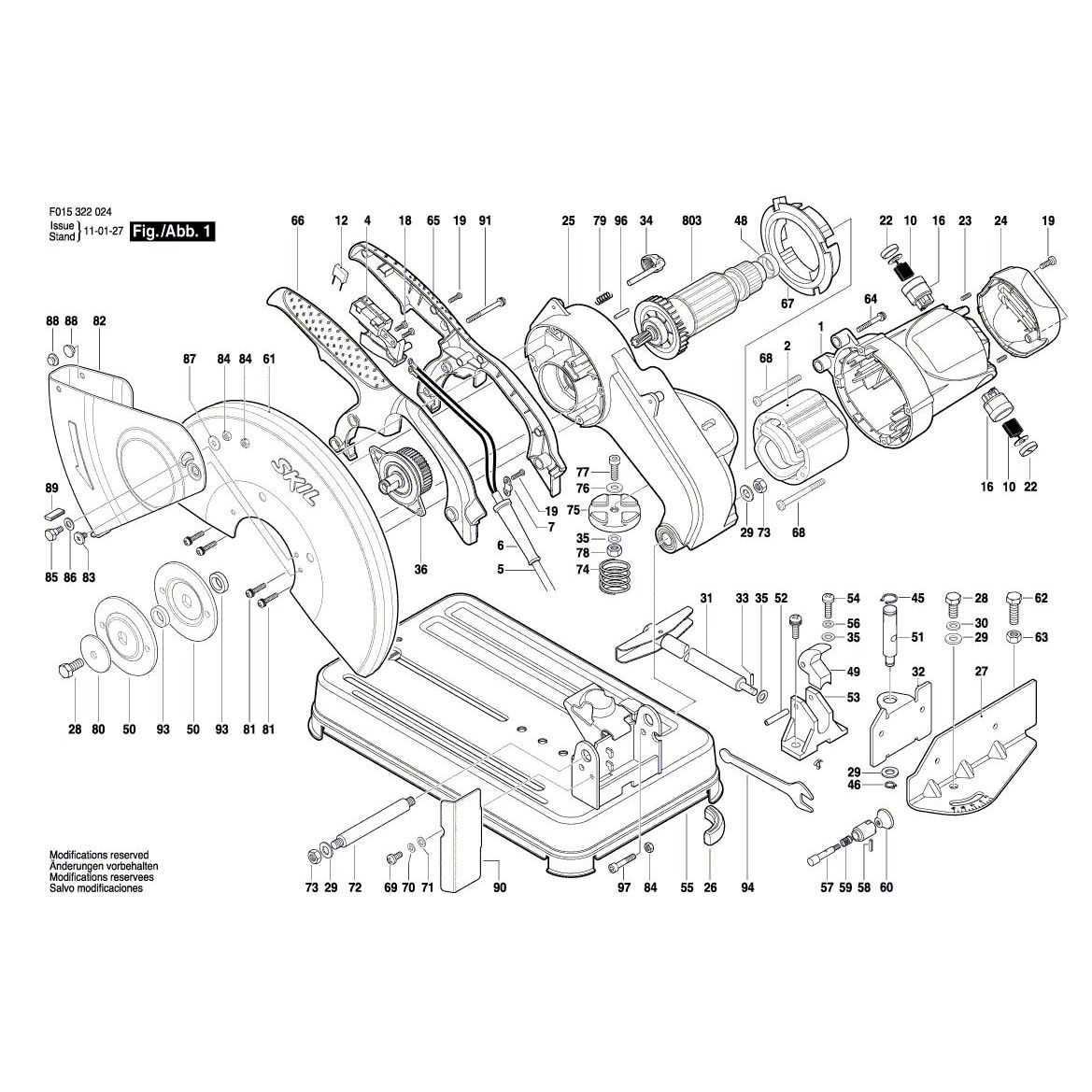
Proper upkeep of your equipment is essential for longevity and optimal performance. Regular checks and timely interventions can significantly enhance functionality and prevent costly repairs.
1. Regular Inspection: Conduct frequent assessments to identify wear and tear. Look for any signs of damage or deterioration that could affect performance.
2. Cleanliness is Key: Ensure that all components are free from dirt and debris. Use a soft brush or compressed air to maintain cleanliness, as buildup can lead to inefficiency.
3. Lubrication: Apply appropriate lubricants to moving parts as specified in the manual. Proper lubrication minimizes friction and extends the life of the equipment.
4. Replacement Schedule: Adhere to a replacement timetable for worn-out elements. Staying proactive helps avoid unexpected breakdowns and maintains reliability.
5. Storage Conditions: Keep the equipment in a suitable environment to prevent corrosion and damage. Protect it from extreme temperatures and moisture.
By following these maintenance strategies, you can ensure that your machinery continues to operate at peak efficiency, providing the ultimate in reliability and performance.
Comparing 026 with Other Diagrams
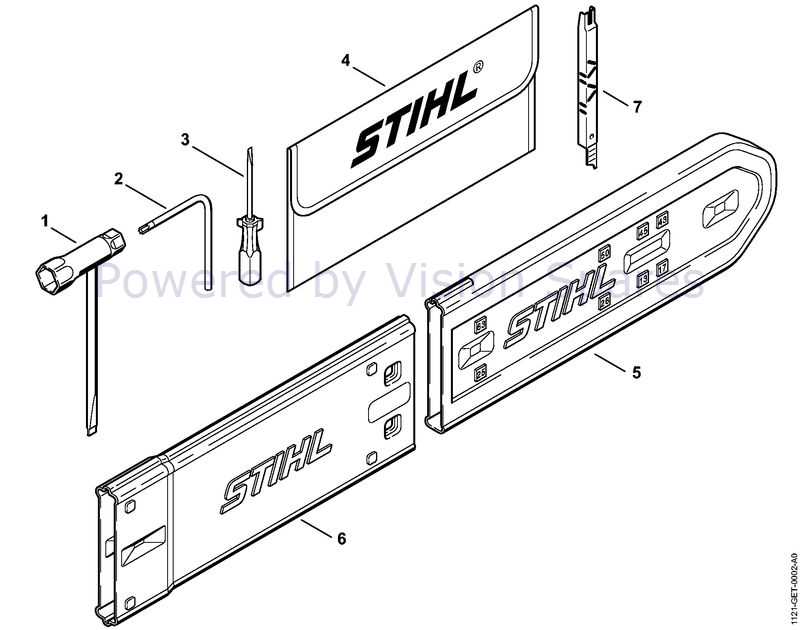
Analyzing the distinctions between various schematics provides valuable insights into their functionality and design intricacies. By understanding how one model contrasts with others, users can make more informed decisions regarding their applications and maintenance strategies.
Key Features to Consider
- Design Complexity
- Ease of Understanding
- Detail Level
- Compatibility with Other Models
Similarities and Differences
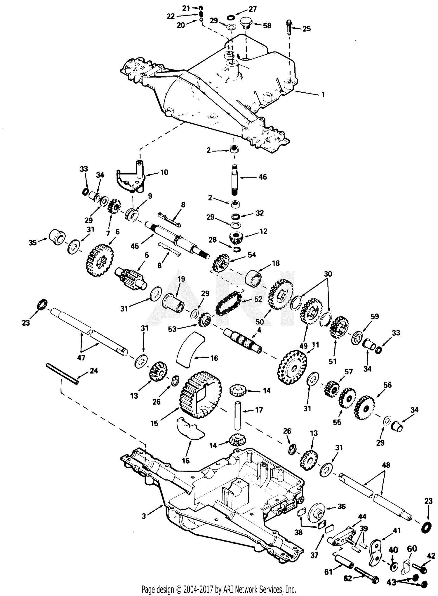
- Both types may serve similar purposes, yet their layout and organization can differ significantly.
- Some may prioritize clarity, while others focus on comprehensive detail.
- Compatibility with various components can vary, influencing user choice.
Applications of the 026 Parts Diagram
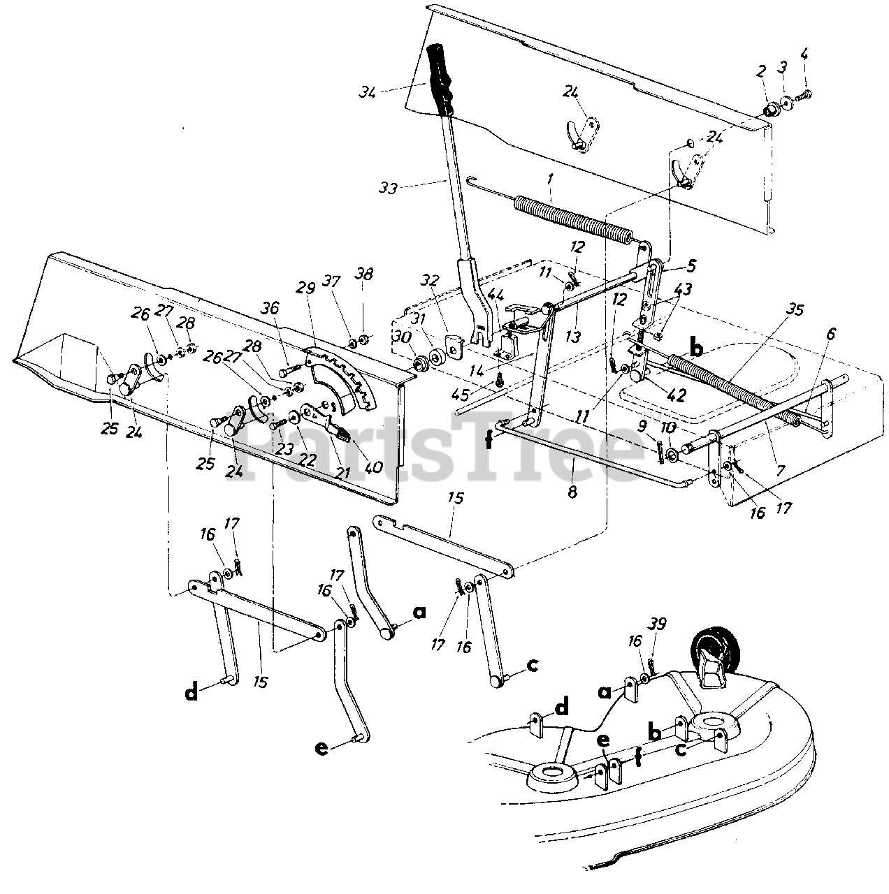
The representation of component layouts serves as a crucial tool across various fields, facilitating understanding and maintenance. By providing a visual guide, it enhances communication among professionals, ensuring clarity in identifying and replacing essential elements.
Industry Utilization
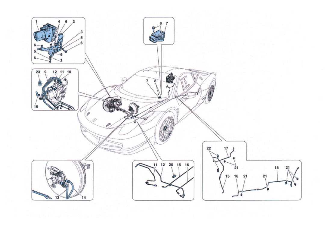
In manufacturing and repair sectors, such visual aids are indispensable. They allow technicians to quickly locate and assess individual elements, leading to efficient troubleshooting and minimized downtime. Additionally, these illustrations support training initiatives, enabling newcomers to familiarize themselves with complex systems.
Research and Development
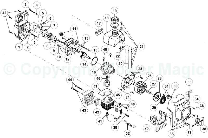
In R&D, detailed layouts are vital for innovation. They assist engineers in analyzing designs, optimizing functionality, and predicting potential issues before implementation. By enabling a comprehensive review, such resources ultimately drive advancements in technology and efficiency.
Tools Required for 026 Repairs
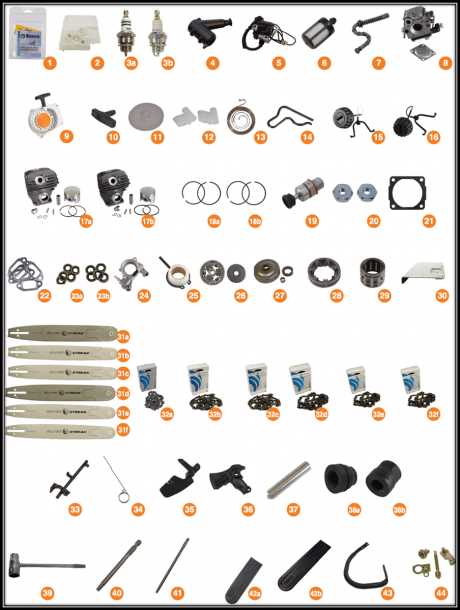
When undertaking maintenance or repairs on specific equipment, having the right tools at your disposal is crucial for efficiency and effectiveness. A well-equipped toolkit not only simplifies the process but also ensures that tasks are completed safely and accurately. Below is a list of essential instruments needed to carry out repairs seamlessly.
Essential Hand Tools
Basic hand tools form the backbone of any repair operation. A set of screwdrivers, pliers, and wrenches will allow you to tackle most tasks with ease. Additionally, a reliable socket set can provide the necessary leverage and reach for those hard-to-access areas, while a pair of sturdy gloves will protect your hands during the process.
Specialized Equipment
In some cases, more specialized equipment is required to address specific issues. Items such as torque wrenches, feeler gauges, and multimeters can be invaluable for precise adjustments and diagnostics. Furthermore, a well-lit work area equipped with a magnifying glass or a headlamp can greatly assist in inspecting intricate components and ensuring that everything is in optimal condition.
Interpreting Symbols in the Diagram
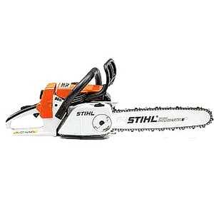
Understanding the representations within technical illustrations is crucial for effective communication and comprehension. These visual cues serve as a universal language, allowing users to decode complex information swiftly and accurately.
Common Symbol Types
Various icons and notations are utilized to convey specific meanings. Recognizing these can enhance one’s ability to navigate through the visual material with ease.
| Symbol | Description |
|---|---|
| ⚙️ | Indicates mechanical components. |
| Represents tools required for assembly. | |
| ⚡ | Denotes electrical connections or components. |
Decoding Complex Representations
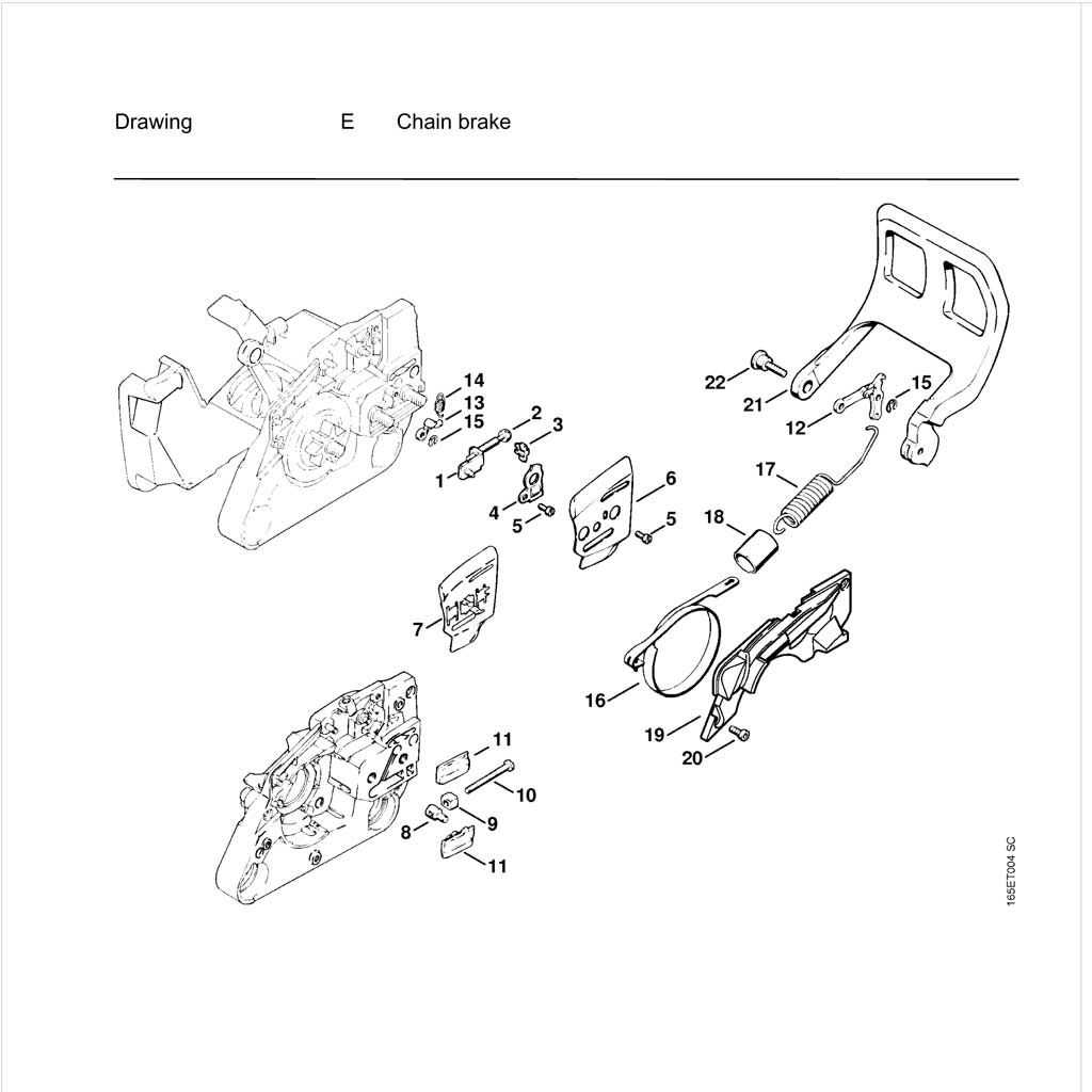
For intricate illustrations, breaking down each symbol step-by-step can facilitate better understanding. Familiarity with these representations ultimately leads to more efficient usage and troubleshooting.
Upgrades for 026 Parts Efficiency
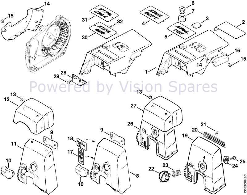
Enhancing the functionality of machinery components can lead to significant improvements in overall performance. By focusing on key modifications, users can maximize the effectiveness and longevity of their equipment.
- Utilize high-quality materials to reduce wear and tear.
- Incorporate advanced lubrication systems to improve friction management.
- Implement precision engineering techniques for better fit and alignment.
Moreover, regular maintenance and timely replacements are crucial for sustaining efficiency. Here are some recommended practices:
- Schedule routine inspections to identify potential issues early.
- Upgrade to modern components that offer enhanced capabilities.
- Invest in training for personnel to ensure proper handling and installation.
These strategies can ultimately lead to a more reliable and efficient operation, saving time and resources in the long run.
Resources for 026 Diagram Support
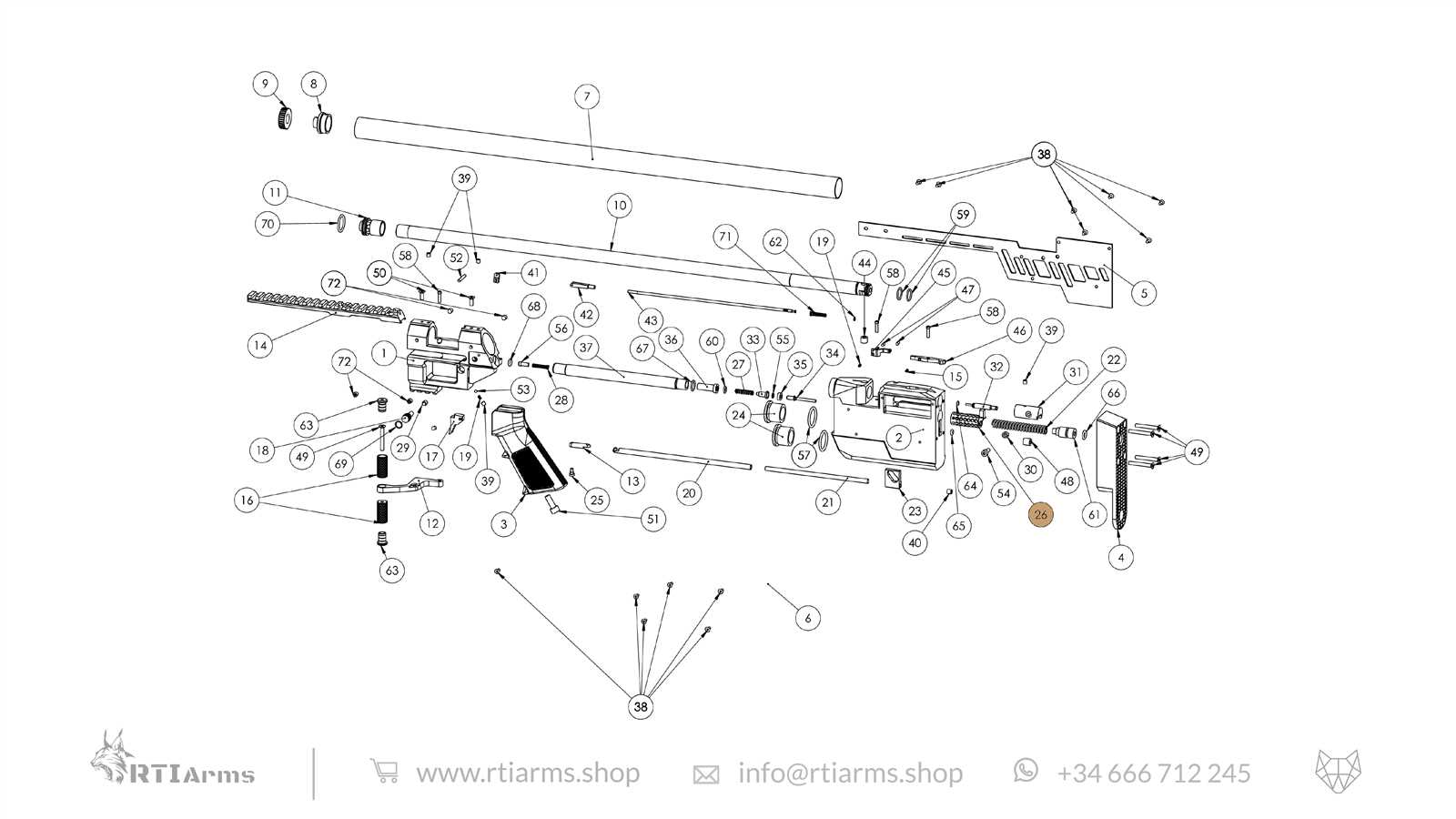
This section aims to provide valuable information and tools to assist users in understanding the intricacies of their specific system layouts. Whether for maintenance or enhancement, having access to accurate resources can significantly streamline the process and improve overall efficiency.
Online Communities
Engaging with online forums and social media groups can offer insights from experienced individuals. These platforms often feature discussions, tips, and shared experiences that can aid in troubleshooting and optimizing the structure.
Official Documentation
Referencing manufacturer manuals and technical guides is crucial for in-depth knowledge. These documents typically contain detailed explanations and illustrations, ensuring that users have the necessary information to navigate their configurations effectively.