| Current Regulation |
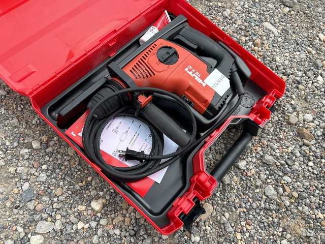
Manages the electrical flow, ensuring safe and stable operation. |
Motor and Drive System Explained
The motor and drive mechanism form the core of any high-performance drilling tool, delivering the necessary power and control for efficient operation. Understanding how these components work together is crucial for maintaining the machine’s optimal performance. Below, we explore the main features of this system, how they contribute to functionality, and what users should be aware of for better tool management.
Core Components of the Motor
- Electric Motor: This component transforms electrical energy into mechanical motion, powering the tool’s essential functions.
- Rotor and Stator: These parts generate rotational force through electromagnetic interaction, driving the machine’s movement.
- Cooling Mechanism: Built-in fans or heat sinks keep the motor from overheating, ensuring durability during extended use.
Drive Mechanism Features
- Transmission Gears: These regulate the torque and speed, providing control over drilling power and precision.
- Impact System: For hammering operations, this system converts rotational energy into a percussive motion, increasing efficiency in tough materials.
- Vibration Dampening: Helps reduce the shock transmitted to the user, improving comfort and safety during heavy-duty tasks.
By keeping these elements in check and ensuring proper maintenance, users can extend the life of their machine and a
Role of the Handle and Grip
The handle and grip are crucial components in the overall functionality and comfort of any power tool. They not only provide control and stability but also enhance user safety by reducing strain and vibration during extended use. By ensuring a firm hold, these elements contribute to precision and reduce the risk of mishandling.
Comfort and Ergonomics
A well-designed handle improves the user’s comfort, especially during long sessions. The ergonomic design plays a vital role in minimizing fatigue, allowing for better handling and accuracy. The materials and contour of the grip ensure that the tool feels natural in the user’s hand, reducing discomfort and improving control over the operation.
Control and Safety
The grip offers critical control over the tool, ensuring that the user can apply the necessary force while maintaining balance. This control helps in preventing slippage and accidents, making the tool safer to operate even in demanding conditions. A firm, secure grip is essential to ensure that the user can perform tasks with accuracy and confidence.
Internal Electrical Wiring and Connections
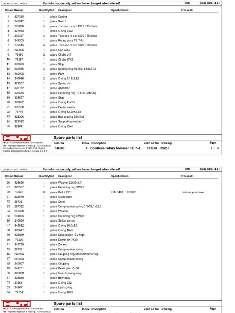
The internal electrical wiring and connections of power tools are crucial for ensuring optimal performance and safety. These internal components provide the necessary pathways for electrical current to flow between key parts, facilitating the smooth operation of the device. Understanding how the wiring is arranged and how each connection functions can help in diagnosing issues or performing repairs when needed.
Most systems rely on a network of insulated cables, connectors, and terminals that work together to supply power to various mechanisms within the tool. Properly installed wiring helps prevent electrical malfunctions, overheating, or potential hazards. This intricate network is designed to maintain a stable flow of electricity while minimizing any risk of short circuits or other electrical failures.
Careful attention to the quality and condition of these connections is essential, as any loose or damaged wiring can lead to inefficiencies or complete breakdowns. Ensuring that the electrical components are securely fastened and protected from wear and tear is key to the longevity and safety of the equipment.
Importance of the Depth Gauge
The depth gauge is a critical feature for precise and consistent drilling. It helps users achieve the exact drilling depth, preventing over-drilling and ensuring the material’s integrity. Whether working on delicate surfaces or tougher materials, the gauge offers control, saving time and resources by eliminating the guesswork.
Ensuring Precision
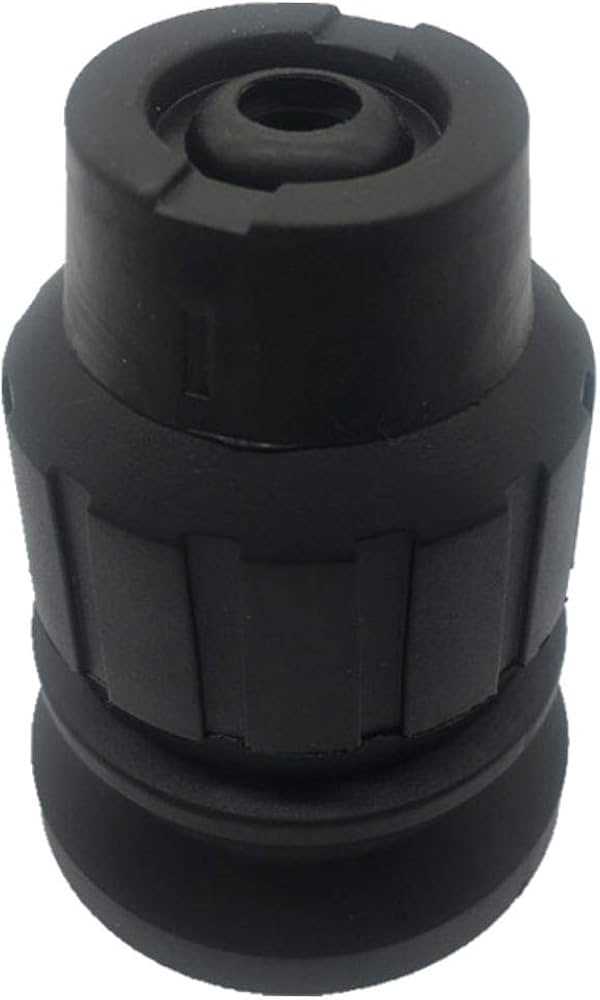
Using a depth gauge guarantees uniformity across multiple holes, especially in projects requiring repetitive drilling. The accuracy it provides is essential for tasks that demand exact hole depths, contributing to the overall quality of the work. Without this tool, it would be challenging to maintain the necessary depth across various points.
Preventing Damage
By setting a maximum depth, the gauge minimizes the risk of accidental damage to the material. It serves as a safeguard, particularly when working with sensitive materials that could be compromised by drilling too deep. The ability to control depth effectively protects both the tool and the material from unnecessary wear or damage.
Impact of the Trigger Mechanism
The trigger mechanism plays a crucial role in ensuring precise control over the tool’s performance. Its design directly influences how the user engages the tool, affecting both speed and accuracy. A well-engineered trigger allows for smooth transitions between power levels, providing the operator with a seamless experience while maintaining optimal control.
Key Functional Elements
The primary components of the trigger mechanism are responsible for initiating the flow of energy to the motor. This flow determines how responsive the tool becomes under varying loads and conditions. Properly calibrated triggers can reduce wear and tear, extend the tool’s operational life, and improve overall efficiency.
Operational Advantages
When designed with precision, the trigger system can significantly enhance user safety by allowing for faster reaction times and reducing strain on the operator. It provides essential feedback during use, enabling the user to
Maintenance of the Gearbox Assembly
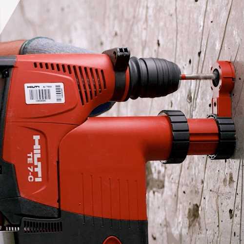
Proper maintenance of the gearbox assembly is essential to ensure optimal performance and longevity of the tool. Regular inspection and servicing can prevent unnecessary wear and damage, which could lead to costly repairs or operational failures. This process involves checking the integrity of key components, such as gears, bearings, and lubrication systems, to maintain smooth operation under various working conditions.
Inspection of the gearbox components should be performed periodically to detect signs of wear, corrosion, or improper alignment. Pay particular attention to the condition of the gear teeth and ensure they are free from cracks or chips. If any irregularities are found, it’s crucial to address them before they compromise the unit’s functionality.
Lubrication plays a critical role in the gearbox’s performance. Over time, the grease or oil can break down, leading to increased friction and potential overheating. It’s recommended to replace the lubricant according to the manufacturer’s guidelines to avoid unnecessary stress on the internal mechanisms. Always use the specified type of lubricant to ensure compatibility with the assembly’s materials.
Reassembly and Testing should be done with precision after cleaning and replacing worn-out parts. After reassembling, test the gearbox to ensure it operates smoothly without unusual noises or vibrations. If any issues arise, it may be necessary to adjust the alignment or replace damaged components.
Replacing Consumable Parts
Maintaining the efficiency of your tool involves replacing key components that wear out over time due to frequent use. These parts are essential for ensuring optimal performance and preventing potential malfunctions. Knowing when and how to replace these elements can greatly extend the life of the equipment and improve overall safety and productivity.
When it comes to replacing these essential components, the following steps should be followed:
- Identify the worn-out items by checking for signs of damage or reduced performance.
- Acquire high-quality replacements that are compatible with your specific model.
- Follow the proper disassembly process to remove the old components safely.
- Install the new parts carefully, ensuring they are securely fitted to avoid any operational issues.
Regularly replacing consumables is a simple yet effective way to keep your tool in top condition and avoid costly repairs. For best results, always refer to the manufacturer’s recommendations regarding replacement intervals and specifications.
Safety Precautions for TE 7-C
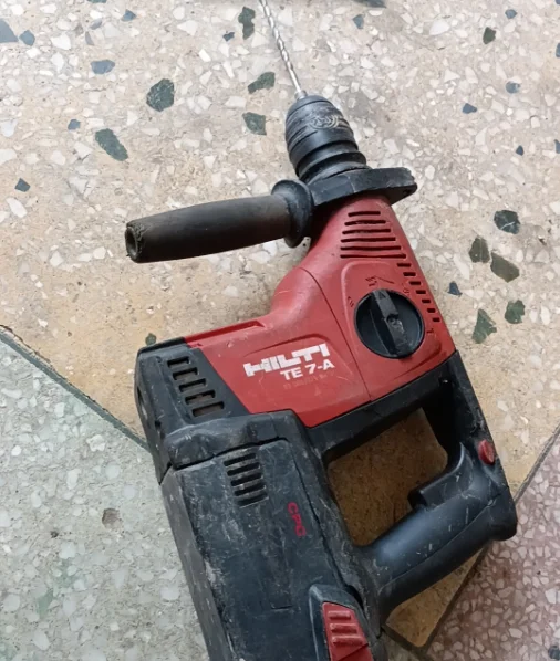
When operating power tools designed for heavy-duty drilling and chiseling, ensuring personal and environmental safety is paramount. Proper use, understanding of the device’s functionality, and adherence to recommended guidelines can significantly reduce risks. Always prioritize safety to prevent accidents and maintain optimal performance.
Before starting any work, it is essential to inspect the equipment thoroughly. This includes checking for any damage, ensuring all components are correctly secured, and verifying that the tool is in good working condition. Wearing protective gear such as goggles, gloves, and ear protection is also highly recommended to guard against potential hazards like debris, noise, and vibrations.
| Precaution |
Description |
| Personal Protective Equipment |
Wear safety goggles, ear protection, and sturdy gloves to safeguard against flying debris, high noise levels, and vibrations. |
| Inspection |
Before use, verify that all components are secure and there are no visible damages to the equipment. Ensure the tool is properly maintained and serviced regularly. |
| Safe Handling |
Always hold the tool firmly with both hands and keep your body stable while working to avoid slips and accidents. |
| Work Environment |
Maintain a clean and clutter-free workspace to minimize the risk of tripping hazards and ensure tools and materials are easily accessible. |
| Power Source |
Make sure the power supply is compatible with the tool’s requirements. Avoid using the equipment in wet or damp environments unless specifically designed for such conditions. |
