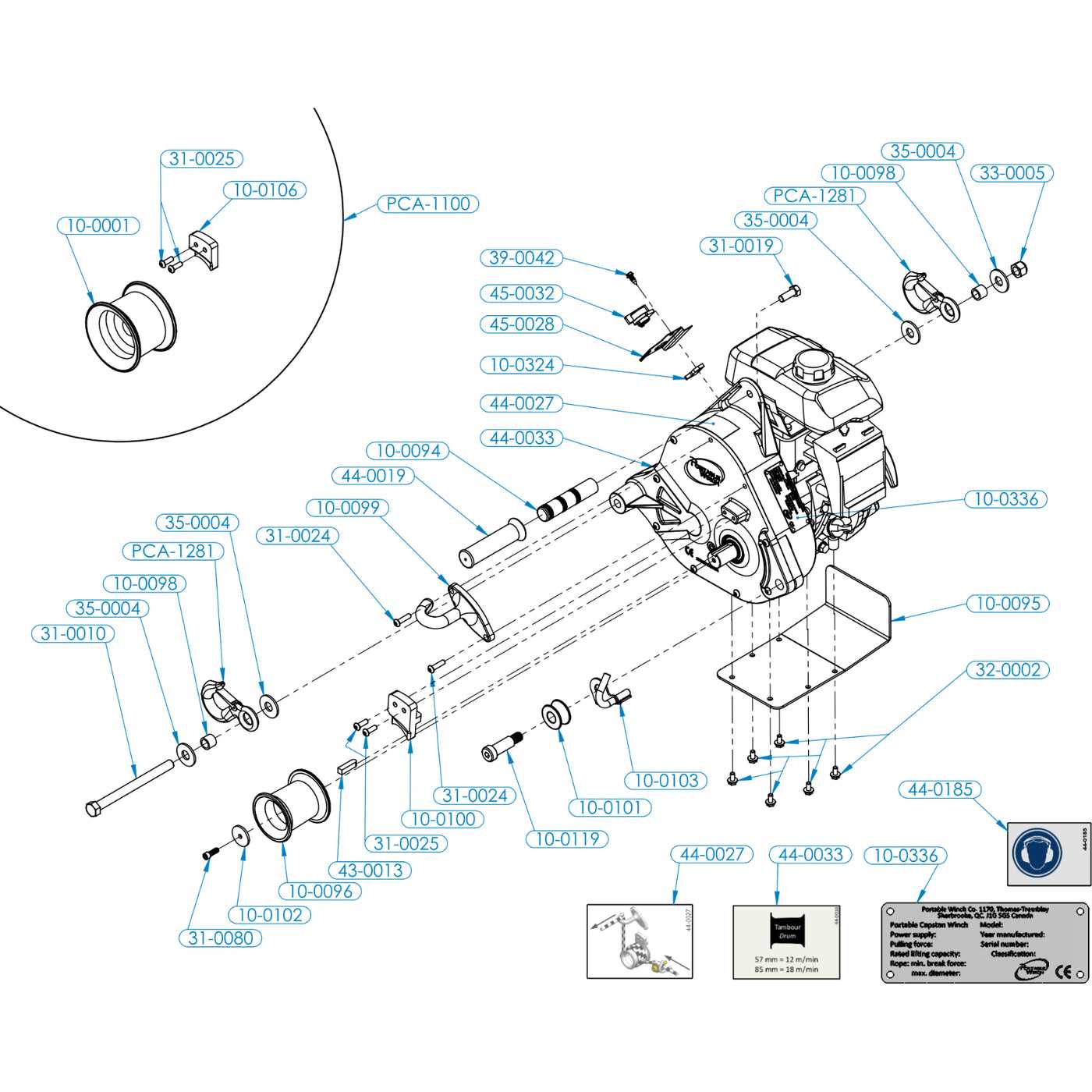
Understanding the configuration and structure of mechanical systems is essential for maintaining and repairing various machinery. A well-organized visual representation helps in identifying different elements and understanding how they work together. This guide provides a detailed look into the layout of critical components in a widely used machine model, making it easier to troubleshoot, service, and optimize performance.
By examining the arrangement and connections between key elements, users can gain insights into the operational flow and ensure that each part functions correctly. This approach simplifies the process of locating specific items during assembly or repair, enhancing both the accuracy and efficiency of mechanical work.
Whether you are looking to improve your knowledge or fix a technical issue, a clear understanding of the structural organization of these mechanical units will be your reliable resource for successful maintenance and repairs.
Honda GX270 Engine Parts Diagram
The structure of this robust power unit is composed of numerous interconnected components. Each element plays a critical role in ensuring the system operates efficiently. The layout is designed for optimal performance and durability, allowing the machine to withstand demanding conditions.
Core Components
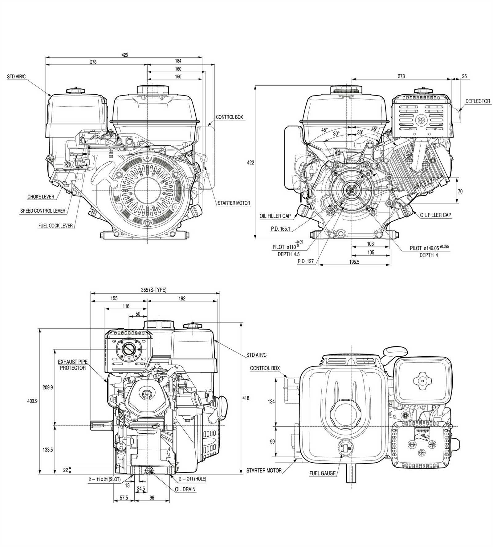
Key elements within the assembly include mechanical and electrical parts responsible for generating power and maintaining stability. These essential components work together, ensuring smooth functionality and consistent output. Proper maintenance of these elements is vital to prevent breakdowns and extend the life of the system.
Functional Interactions
The various components are intricately arranged, creating a balanced interaction. Every piece, from the power source to smaller connectors, is strategically aligned to maximize efficiency. Understanding this arrangement helps in troubleshooting and improving overall performance.
Key Components of the GX270 Engine
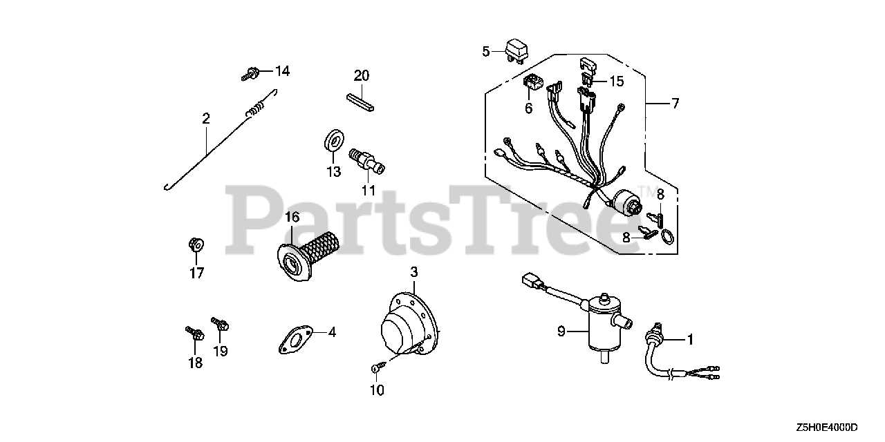
Understanding the essential mechanisms of this power unit is vital for maintaining optimal performance. Each component plays a critical role in ensuring the smooth operation and longevity of the machine.
Main Internal Mechanisms
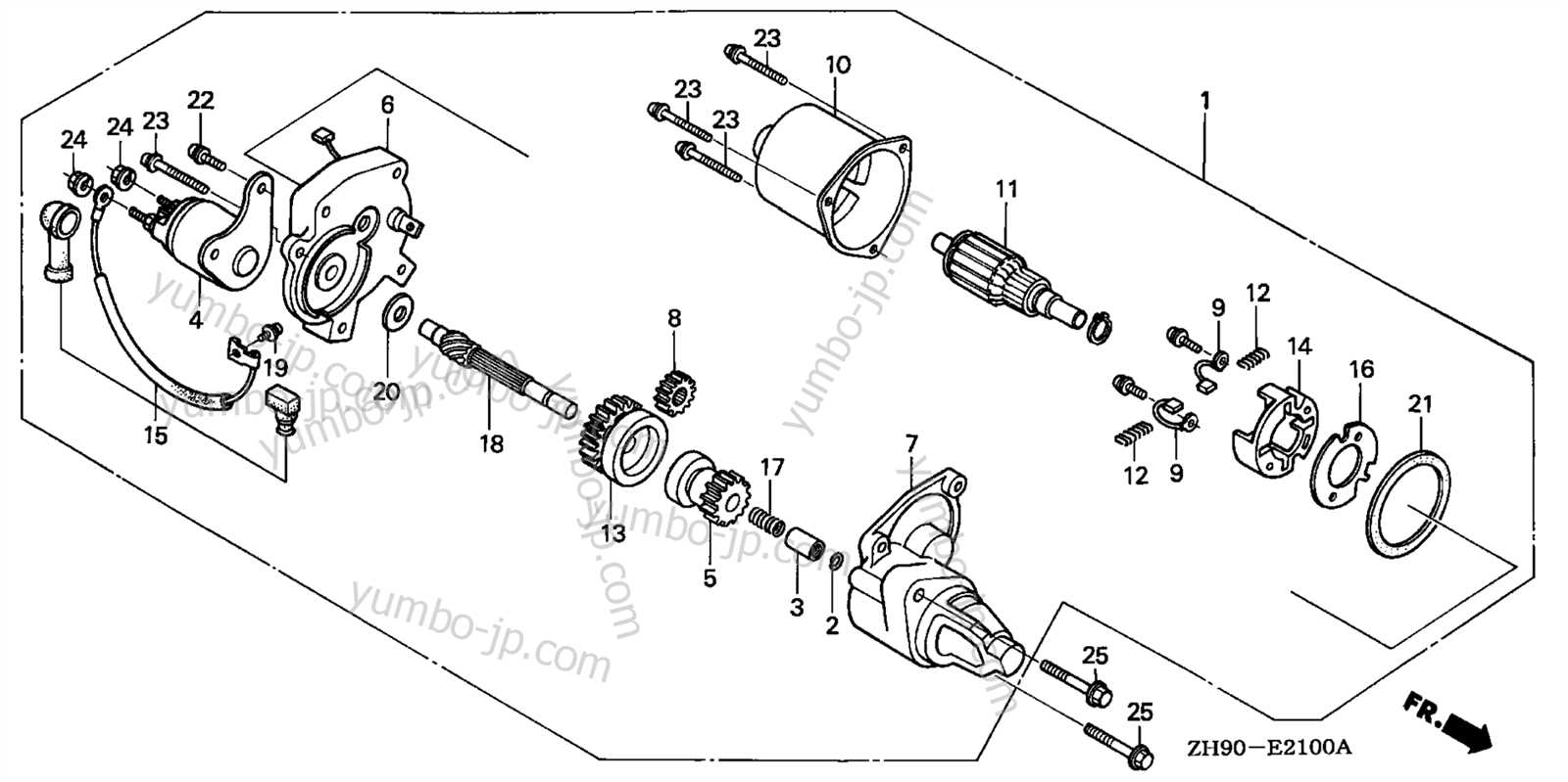
- Cylinder and Piston: The primary elements responsible for combustion, converting fuel into mechanical energy.
- Crankshaft: Transfers the linear motion of the piston into rotational force, powering other systems.
- Camshaft: Controls the opening and closing of valves, ensuring precise timing for air and fuel intake.
External Supporting Systems
- Fuel System: Regulates the flow of fuel into the combustion chamber, ensuring efficient energy production.
- Cooling System: Prevents overheating by circulating coolant, maintaining optimal temperature during operation.
- Ignition System: Initiates combustion with a precise spark, critical for engine startup and sustained performance.
Exploring the Fuel System Layout
The fuel delivery mechanism plays a crucial role in ensuring efficient operation. It comprises several interconnected components that work together to control the flow and combustion of fuel. Understanding this arrangement allows for better maintenance and troubleshooting of performance issues.
| Component | Function |
|---|---|
| Fuel Tank | Stores the fuel and supplies it to the system. |
| Fuel Line | Transports the fuel from the tank to the carburetor. |
| Carburetor | Mixes fuel with air in proper proportions for combustion. |
| Fuel Filter | Removes impurities from the fuel before it reaches the carburetor. |
Understanding the Ignition System Assembly
The ignition system is crucial for ensuring smooth operation of the machinery, as it provides the initial spark necessary to ignite the air-fuel mixture. Proper functioning of this system directly impacts overall performance and efficiency.
Key components of the system include a device that generates high voltage, allowing for a spark to form. This spark is timed precisely to ensure the optimal firing sequence. A series of connectors and wiring transfers energy to the combustion chamber, where the controlled explosion occurs, powering the mechanical movement.
Understanding how each part of the assembly interacts is essential for maintaining reliability and preventing issues. Regular checks can prevent misfires and ensure that the power source remains consistent.
Air Intake and Exhaust Flow
The efficiency of a combustion system depends heavily on how air enters and exits the system. By managing airflow correctly, the overall performance and fuel consumption can be optimized, ensuring smoother operation and better longevity of mechanical components.
| Component | Function |
|---|---|
| Air Filter | Prevents debris from entering the combustion chamber, ensuring clean air intake. |
| Carburetor | Regulates the mixture of air and fuel, balancing power output and efficiency. |
| Exhaust Valve | Releases combustion gases, maintaining pressure balance for optimal operation. |
| Muffler | Reduces noise and controls the flow of exhaust gases, preventing backpressure. |
Detailed View of the Cylinder Block
The cylinder block serves as the fundamental structure within an internal combustion system, housing several critical components. It plays a vital role in ensuring the proper functioning of various mechanisms while supporting the overall integrity of the unit. Understanding its design and features is essential for anyone involved in maintenance or repairs.
Key Features of the Cylinder Block
This structure typically consists of durable materials capable of withstanding high pressures and temperatures. Its design often includes machined surfaces for precise sealing and alignment, facilitating effective combustion and minimizing the risk of leaks. Additionally, the cylinder block integrates various channels and passages for coolant and lubrication, promoting efficient thermal management.
Maintenance Considerations
Regular inspections of the cylinder block are crucial to identify wear and tear that may affect performance. Ensuring proper sealing and checking for cracks or corrosion can prevent significant issues down the line. Routine cleaning of coolant passages and adherence to lubrication specifications also contribute to the longevity and reliability of the overall assembly.
Oil System Path and Components
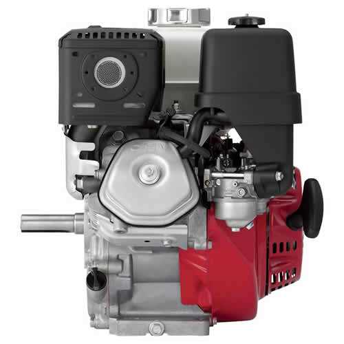
The lubrication system plays a crucial role in maintaining the performance and longevity of a power unit. It ensures that vital components receive the necessary lubrication to minimize friction and prevent wear. Understanding the flow and key elements of this system is essential for effective maintenance and troubleshooting.
Flow of Lubricant
The lubricant circulates through various channels and components, starting from the reservoir. It is then pumped through filters to remove impurities before reaching critical areas. This continuous flow not only lubricates but also helps in cooling and cleaning the internal components, ensuring smooth operation.
Key Components
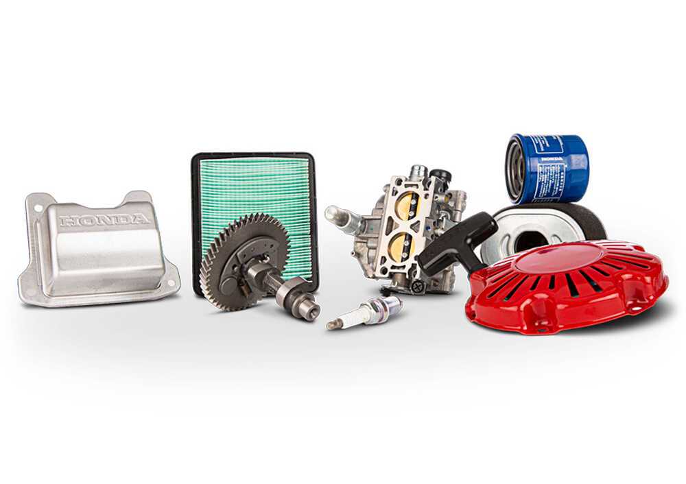
Several critical elements contribute to the efficiency of the lubrication system. The primary components include:
- Oil Pump: Responsible for creating pressure to circulate the lubricant.
- Oil Filter: Removes contaminants from the lubricant to protect internal surfaces.
- Lubrication Channels: Pathways that direct the flow of lubricant to various parts.
- Reservoir: Holds the lubricant until it is needed for circulation.
Regular inspection and maintenance of these components are vital for optimal performance and reliability.
Carburetor Structure and Function
The carburetor plays a crucial role in the operation of a combustion system by mixing air and fuel in the correct ratio. This device ensures that the internal components receive the right amount of combustible mixture, allowing for optimal performance and efficiency.
Key Components
Several essential components make up the structure of a carburetor. These include the float chamber, main jet, and throttle plate. The float chamber maintains a constant fuel level, while the main jet regulates the amount of fuel delivered to the airflow. The throttle plate controls the engine’s airflow, directly impacting power output and speed.
Operational Mechanism
When the system operates, air flows through the carburetor, creating a vacuum that draws fuel from the float chamber. This mixture of air and fuel is then atomized and delivered to the combustion chamber. The precise control of this mixture is vital for efficient combustion and overall system performance. Any imbalance can lead to issues such as poor fuel efficiency or increased emissions.
Crankshaft and Connecting Rod Mechanism
The crankshaft and connecting rod assembly plays a pivotal role in transforming linear motion into rotational energy, which is essential for the overall functionality of a mechanical system. This mechanism efficiently converts the back-and-forth movement of the pistons into the circular motion needed to power various applications, ensuring smooth operation and performance.
The crankshaft, typically crafted from durable materials, is designed to withstand significant stress while facilitating the rotation required for motion transmission. It features several throws that correspond to the connecting rods, which link it to the pistons. The connecting rods themselves are engineered for flexibility and strength, enabling them to manage the forces generated during operation while maintaining alignment and balance within the assembly.
Understanding the intricacies of this mechanism is crucial for diagnosing issues, performing maintenance, and optimizing performance. Regular inspections and proper lubrication are essential to ensure longevity and efficiency, allowing the system to operate effectively under various conditions.
Cooling System Overview for the GX270

The cooling system plays a vital role in maintaining the optimal operating temperature of a small power unit. Its primary function is to prevent overheating, which can lead to severe damage and reduced efficiency. Understanding the components and operation of this system is essential for ensuring the longevity and reliability of the machinery.
Components of the Cooling System
This system comprises several key elements that work together to regulate temperature. The main components include:
| Component | Function |
|---|---|
| Radiator | Dissipates heat from the coolant |
| Water Pump | Circulates coolant throughout the system |
| Thermostat | Regulates coolant flow based on temperature |
| Coolant Reservoir | Stores excess coolant and maintains pressure |
Operating Principle
The cooling mechanism relies on the circulation of a fluid that absorbs heat from the internal components. As the unit operates, the coolant is heated and flows to the radiator, where it releases heat to the environment. The cooled fluid then returns to the unit, ready to absorb more heat. This continuous cycle ensures that the operating temperature remains within safe limits, promoting efficiency and extending the life of the machinery.
Piston and Combustion Chamber Insights
The piston and combustion chamber are critical components that play a vital role in the overall performance and efficiency of a power unit. Understanding their functions and interactions can help in optimizing operation and maintenance, ensuring longevity and reliability.
Functionality of the Piston
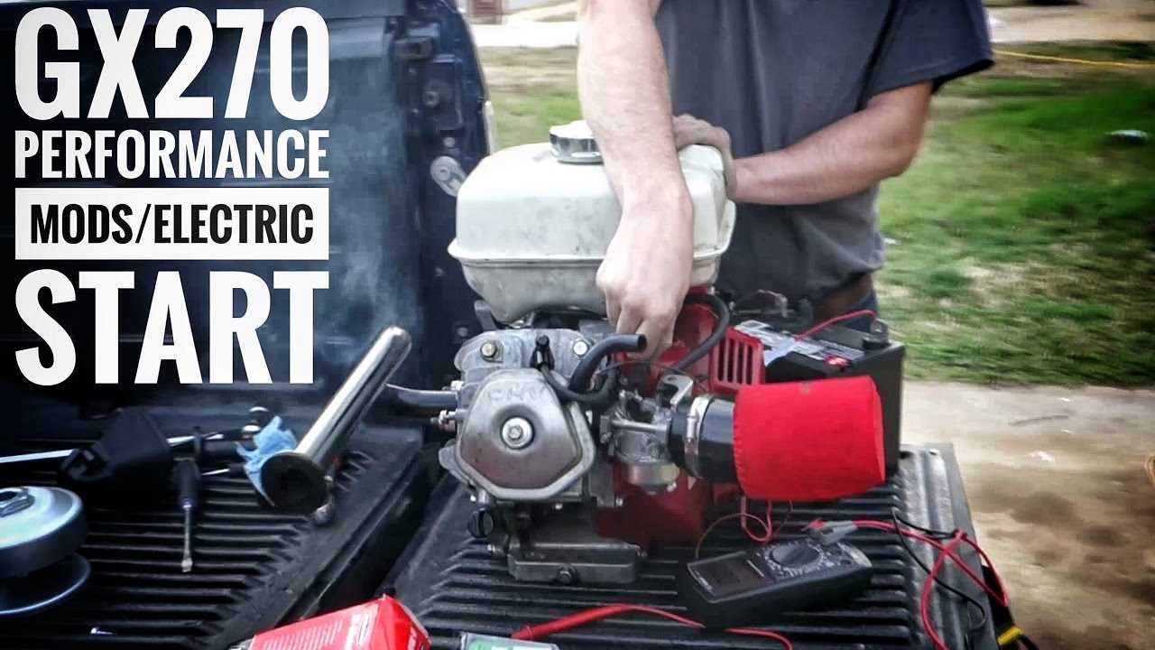
The piston serves several essential functions within the combustion space:
- Converts the energy produced by fuel combustion into mechanical work.
- Maintains a seal to prevent gases from escaping during the combustion process.
- Moves in a reciprocating motion, driving the crankshaft.
Importance of the Combustion Chamber
The design and configuration of the combustion chamber significantly influence performance characteristics:
- Facilitates optimal fuel-air mixing for efficient combustion.
- Enhances the pressure and temperature conditions necessary for effective power generation.
- Affects the emissions produced, impacting environmental compliance.
Understanding these elements is essential for anyone looking to maintain or enhance the functionality of their power units.
Valve System Configuration and Maintenance
The valve mechanism is crucial for the effective operation of internal combustion machinery, controlling the flow of air and fuel into the combustion chamber while allowing exhaust gases to exit. Understanding the layout and upkeep of this system is essential for optimal performance and longevity.
Regular maintenance of the valve system ensures smooth functionality and helps prevent costly repairs. Key aspects include monitoring the alignment, checking for wear, and ensuring that components are properly lubricated.
| Component | Function | Maintenance Tips |
|---|---|---|
| Valves | Regulate air and fuel intake, and exhaust flow | Inspect for damage and replace if worn |
| Valve Springs | Maintain pressure on the valves to ensure proper sealing | Check tension and replace if weak |
| Push Rods | Transmit motion from the rocker arms to the valves | Inspect for bends and lubrication |
| Rockers | Open and close the valves in synchronization | Ensure proper adjustment and lubrication |