When it comes to maintaining and servicing various machinery, a clear understanding of component schematics plays a vital role. These illustrations offer a detailed look at the arrangement and connections of different elements, helping technicians identify how each piece functions within the system.
Interpreting these layouts can streamline troubleshooting and repairs, reducing the time spent on diagnostics. With a comprehensive view of each element’s role and positioning, maintenance becomes more precise, leading to efficient solutions for mechanical issues.
Using these visual guides, technicians can quickly pinpoint potential issues and take proactive measures to prevent larger problems. This approach not only ensures a smoother workflow but also enhances the longevity and performance of the equipment.
Identifying Key Elements in Drawings
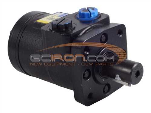
Understanding the critical components within technical illustrations is essential for interpreting their details accurately. These visual representations often serve as blueprints, guiding users through the structural and functional aspects of various assemblies. Identifying specific features within these sketches helps in comprehending how each segment interacts with others in a larger system.
When examining such illustrations, it is vital to focus on the distinct symbols and notations that highlight essential sections. Recognizing these markers can reveal important insights into the object’s operation and its individual segments. A systematic approach to reviewing these visual elements ensures a clear grasp of their practical relevance.
Reading Technical Illustrations Effectively
Interpreting technical visuals requires a structured approach that helps to extract the right information quickly and accurately. These images are designed to convey complex details in a simplified manner, making it essential to understand the components and their relationships within the visual representation.
- Identify Key Elements: Focus on recognizing the main symbols and markers used within the illustration. Knowing the standard notations will allow you to connect visual data with the related specifications.
- Follow the Sequence: Many technical illustrations are organized in a logical flow. Following this sequence step-by-step aids in comprehending how different sections interact with each other.
- Use Reference Guides: Complement your analysis with any available reference materials that can provide further insights into specific areas. These guides often include explanations that clarify the visual elements.
- Analyze Annotations: Carefully review all labels and notes within the illustration. These annotations are crucial for understanding details that might not be immediately visible in the drawing itself.
- Begin with an overview to get a general sense of the layout.
- Zoom in on each section to explore detailed information.
- Cross-check your observations with the accompanying text if available.
- Verify the visual data by comparing it with real-world counterparts if possible.
Effective analysis of technical illustrations is a skill that improves with practice, enabling clearer communication and more precise implementation of the depicted instructions.
Common Symbols in Equipment Blueprints
Understanding the symbols used in equipment blueprints is essential for correctly interpreting technical schematics. These symbols serve as a universal language, allowing anyone to quickly grasp the details of complex mechanical layouts without needing extensive explanations.
Circuit Elements are frequently depicted through standardized icons, representing various components like switches, connectors, and fuses. Recognizing these illustrations helps to trace electrical paths and identify potential issues in the layout.
Mechanical Components are marked using distinct shapes and patterns, indicating items such as gears, levers, and fasteners. Familiarity with these symbols is crucial for analyzing the interactions between different mechanical parts.
Fluid systems are often shown with symbols that describe valves, pumps, and pipelines. These icons make it easier to follow the flow of liquids or gases through a system, ensuring proper operation and maintenance of the equipment.
Exploring Mechanical System Layouts
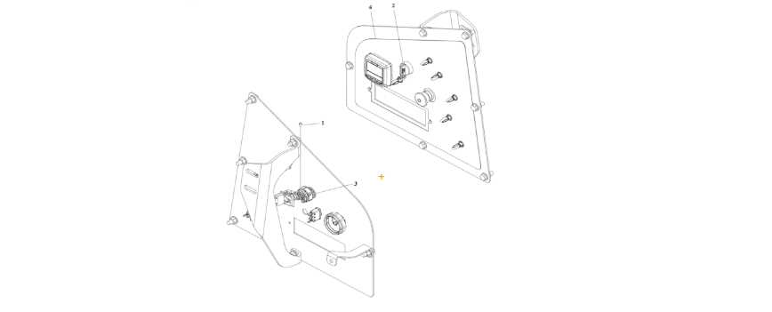
Understanding the arrangement of various components within a mechanical system is crucial for effective maintenance and performance optimization. By examining the configuration of interconnected elements, one can identify the relationships and dependencies that ensure smooth operation.
- Component Positioning: Analyzing the precise placement of each element is key to grasping how they interact within the setup.
- System Integration: Recognizing how individual parts work together helps in identifying potential areas for efficiency improvements.
- Flow Dynamics: Observing the sequence in which mechanical actions occur provides insights into the overall workflow and system performance.
Exploring these layouts allows for a deeper appreciation of the engineering principles involved, guiding both troubleshooting and enhancement efforts.
Decoding Electrical Circuit Representations
Understanding the visual symbols and connections within an electrical schematic is essential for analyzing various systems. These graphical illustrations serve as a guide, helping to interpret the flow of electricity through different components without needing to see the physical setup. By studying these representations, one gains the ability to troubleshoot issues and enhance system performance.
Breaking Down the Symbols
Each symbol within a circuit design holds a specific meaning, representing different elements like resistors, capacitors, or switches. Knowing how to identify and translate these symbols into real-world components enables a deeper insight into the system’s behavior and potential issues.
Tracing the Flow of Electricity
Tracing the electrical path is crucial in comprehending how energy moves from one section to another. By following these routes, it’s possible to pinpoint interruptions or inconsistencies in the connections, making it easier to locate the source of malfunctions or inefficiencies within the system.
Troubleshooting With Schematic References
Understanding technical illustrations is crucial when diagnosing issues in equipment systems. These visual representations provide a clear overview of the connections and components, facilitating efficient problem-solving. By utilizing these references, operators can pinpoint faults and identify the necessary repairs more effectively.
Identifying Common Issues
When issues arise, the first step is to consult the appropriate technical illustrations. Electrical failures, for instance, can often be traced back to a specific connection or component. By following the visual cues, technicians can isolate problems and determine the best course of action.
Implementing Repairs
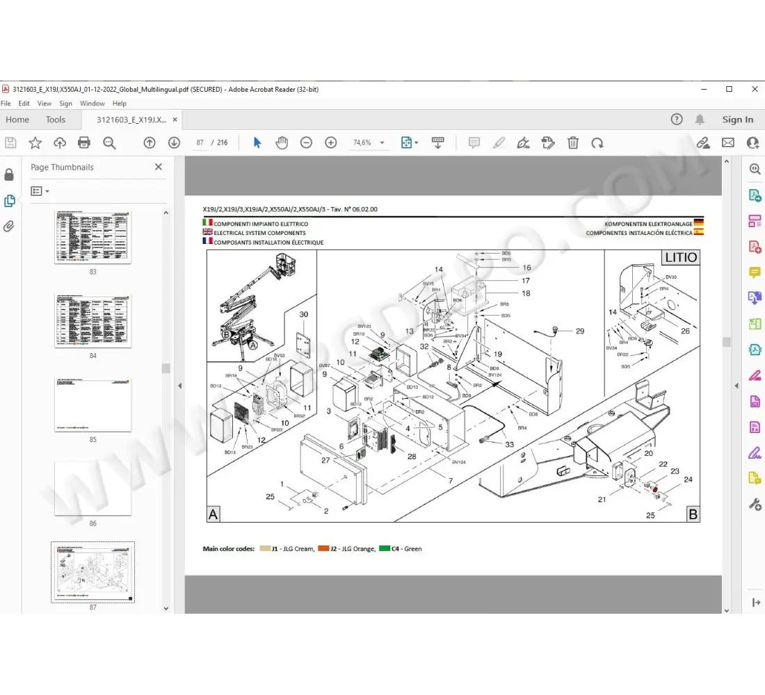
Once a fault has been identified, the schematic becomes an invaluable resource for executing repairs. With a comprehensive understanding of the layout, technicians can ensure that replacements or adjustments are made correctly. Adhering to the layout helps maintain the integrity of the system and reduces the likelihood of future complications.
Optimizing Part Identification Techniques
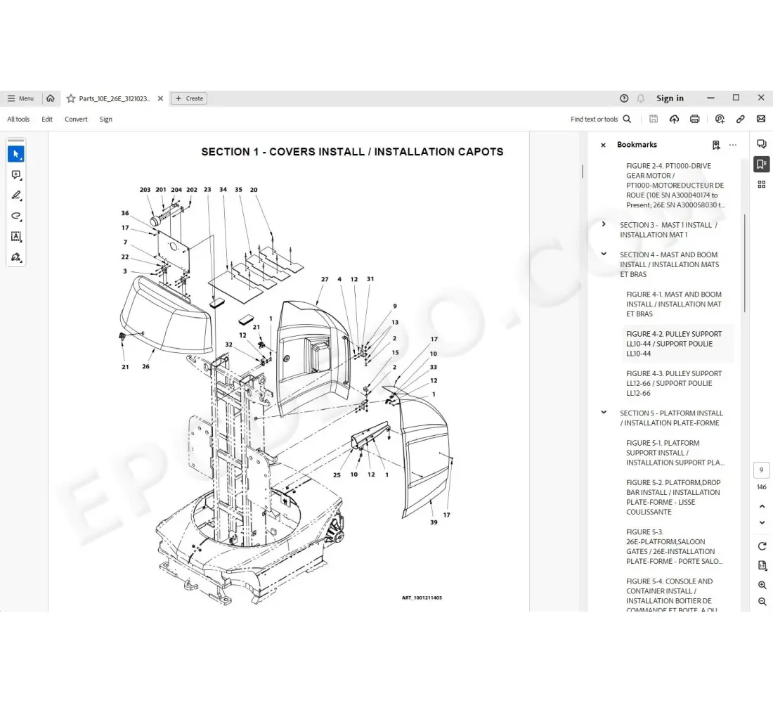
Efficient identification of components is crucial for maintenance and repair processes. By employing systematic approaches, users can enhance their ability to locate and recognize essential elements in machinery. This section explores methods that streamline component recognition, ensuring accuracy and speed during service tasks.
Effective Strategies for Component Recognition
Implementing a structured approach to identify elements can significantly improve workflow. Utilizing digital tools, reference materials, and visual aids can facilitate the identification process. Additionally, creating a database of common components and their specifications can serve as a valuable resource for technicians.
Utilizing Visual References
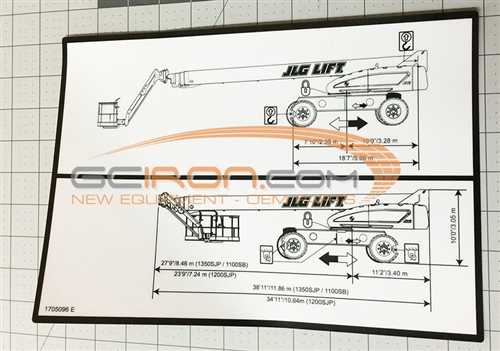
Visual aids play a pivotal role in component identification. High-quality images, diagrams, or schematic representations allow for quick reference, reducing errors in recognition. By integrating these visual tools into standard operating procedures, organizations can enhance overall efficiency and accuracy.
| Technique | Description | Benefits |
|---|---|---|
| Digital Catalogs | Online databases featuring detailed specifications and images. | Quick access and comprehensive information. |
| Color Coding | Assigning specific colors to categories of components. | Facilitates rapid visual identification. |
| Mobile Apps | Applications designed for on-the-go access to identification tools. | Increases flexibility and accessibility. |
Efficient Navigation Through Technical Sheets
Understanding and maneuvering through complex technical documentation is essential for effective maintenance and repair tasks. By mastering the layout and structure of these documents, users can quickly locate vital information, facilitating a smoother workflow.
Key Strategies for Navigation
- Familiarize Yourself with the Layout: Take time to explore the document’s structure, noting the sections and their purposes.
- Utilize Indexes and Tables of Contents: These tools are invaluable for quickly finding specific information without scrolling through entire pages.
- Leverage Search Functions: If available, use the search feature to jump directly to relevant sections or keywords.
- Highlight Important Sections: Mark key areas for easy reference during future consultations.
Effective Reading Techniques
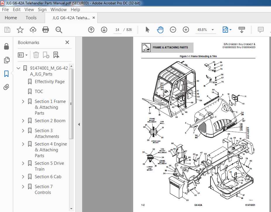
- Skim for Overview: Before diving deep, skim the document to grasp the overall context and major points.
- Focus on Visuals: Diagrams and illustrations can provide quick insights and enhance understanding.
- Take Notes: Jot down critical details or questions that arise during your review to clarify later.
By employing these techniques, individuals can significantly enhance their efficiency when navigating through technical documents, ultimately leading to improved productivity and better outcomes in their tasks.
Organizing Replacement Part Numbers
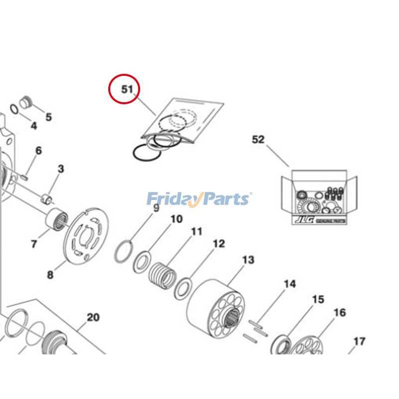
Efficiently managing the identifiers for spare components is crucial for maintaining operational continuity in various machinery. A well-structured system enables users to quickly locate necessary items, minimizing downtime and enhancing productivity. By categorizing these identifiers systematically, users can streamline their maintenance processes and ensure that the correct components are readily accessible when needed.
Establishing a clear naming convention is essential. This involves grouping identifiers based on specific criteria, such as function, size, or compatibility. Utilizing a consistent format helps in avoiding confusion and simplifies the retrieval of information. Additionally, integrating digital tools or databases can significantly enhance the organization of these identifiers, allowing for easy updates and tracking.
Regular audits of the identifier inventory can further improve the efficiency of the system. By reviewing the organization periodically, users can identify outdated or redundant identifiers, facilitating necessary updates. This practice not only keeps the inventory current but also supports effective decision-making when ordering new components.
Analyzing Fluid Systems in Diagrams
The examination of fluid systems within schematics is crucial for understanding the interconnections and functionalities of various components. By studying these visual representations, one can identify how fluids move through systems, the relationships between different parts, and the overall efficiency of the setup. This analysis allows for troubleshooting and optimization, leading to improved performance and reliability.
Identifying Key Components
Recognizing essential elements in the schematic is the first step in understanding the fluid dynamics at play. Each component serves a specific purpose, from pumps to valves, and their arrangement often dictates the system’s efficiency. Effective analysis involves not only identifying these parts but also comprehending their roles and interactions.
Evaluating Flow Patterns
After pinpointing the critical components, the next focus should be on the flow patterns depicted in the schematic. Observing how fluids navigate through the system reveals potential bottlenecks and areas for enhancement. Understanding these flow dynamics is vital for ensuring optimal performance and addressing any inefficiencies that may arise.
Comparing Different Drawing Standards
In the realm of technical illustrations, various standards exist to guide the creation and interpretation of visual representations. Each standard has its unique set of rules and conventions, impacting how information is conveyed and understood by professionals across different industries. Understanding these distinctions is crucial for effective communication in engineering and design practices.
Industry-Specific Standards
Different fields often adopt specific drawing protocols tailored to their particular requirements. For instance, architectural designs typically follow guidelines that emphasize spatial relationships and materials, while mechanical engineering sketches focus on dimensions and tolerances. These standards ensure that practitioners within each sector can interpret drawings consistently and accurately, fostering collaboration and reducing the likelihood of errors.
International vs. National Standards

There is also a notable contrast between international and national standards in technical drawing. International standards aim to provide a unified approach that can be understood globally, promoting cross-border collaboration. Conversely, national standards may incorporate local practices and preferences, reflecting regional nuances in design and manufacturing. This divergence can influence how drawings are developed and utilized across different markets.