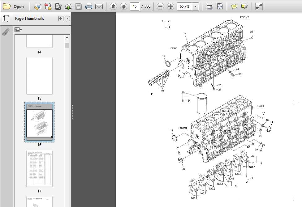
The intricate web of machinery relies heavily on a clear representation of its various elements. This visual aid serves as an essential tool for users, providing clarity on the arrangement and function of each piece. By delving into these illustrations, one can enhance their comprehension of how each segment interconnects, ensuring efficient operation and maintenance.
For technicians and enthusiasts alike, grasping the configuration of equipment is crucial for troubleshooting and repairs. With an accurate visual reference, individuals can pinpoint issues swiftly and implement effective solutions. This clarity not only streamlines the repair process but also contributes to the longevity of the machinery in question.
Moreover, such visual representations facilitate better training and onboarding for new team members. A well-structured overview of the equipment’s composition allows for a smoother learning curve, empowering newcomers to become proficient in their roles. Ultimately, understanding the layout of these components fosters a culture of safety and efficiency in any operational setting.
Understanding Doosan Parts Diagrams
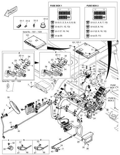
Comprehending the intricacies of technical illustrations is essential for effective machinery maintenance and repair. These visual representations serve as invaluable resources, providing detailed information about individual components and their interconnections within various systems.
To fully grasp the significance of these illustrations, it is vital to familiarize oneself with the key elements that they encompass:
- Identification: Each component is typically labeled, allowing for quick reference and easy identification.
- Placement: The positioning of parts in relation to one another is illustrated, showcasing how each piece fits within the larger assembly.
- Functionality: Annotations may explain the purpose of specific components, clarifying their roles in the overall operation.
Utilizing these visual guides effectively can enhance understanding and streamline the troubleshooting process. Here are some essential tips for interpreting these illustrations:
- Start with the overall layout to gain context on how components interact.
- Pay attention to the labels, as they provide critical information about each element.
- Refer to the accompanying documentation for additional insights and instructions.
- Cross-reference with actual machinery to reinforce learning and application.
By mastering the ability to interpret these visual aids, operators and technicians can improve their efficiency and accuracy when working with complex machinery.
Importance of Accurate Parts Diagrams
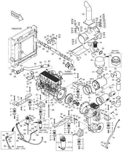
Precision in visual representations of components is crucial in various industries. These illustrations serve as essential guides for assembly, maintenance, and troubleshooting. Clear and detailed depictions enable users to quickly identify necessary elements, ensuring effective repairs and replacements. Without such accuracy, the likelihood of errors increases, leading to potential operational inefficiencies and costly downtime.
Enhancing Efficiency and Reducing Errors
Well-crafted visual guides streamline workflows by providing clear instructions on component arrangement and functionality. This clarity minimizes misunderstandings and errors during repairs, allowing technicians to complete tasks more efficiently. In industries where time is money, reducing mistakes and enhancing productivity is paramount.
Facilitating Training and Knowledge Transfer
Accurate illustrations are invaluable for training new employees. They offer a visual learning tool that simplifies complex concepts, making it easier for trainees to grasp intricate systems. As knowledge is passed down, these resources become essential for maintaining consistency and quality across teams, contributing to overall organizational success.
Common Components in Doosan Machinery
The machinery designed for heavy-duty applications is comprised of a variety of essential elements that work cohesively to ensure optimal performance and reliability. Each component plays a vital role in enhancing the efficiency of operations, providing durability, and facilitating maintenance.
Engine: The heart of any machine, the engine is responsible for generating power. Its efficiency directly influences the overall productivity and operational costs.
Hydraulic System: This system utilizes pressurized fluid to perform various functions, enabling lifting, steering, and other critical operations. Its reliability is paramount for smooth functionality.
Transmission: This component transmits power from the engine to the wheels or tracks, allowing for controlled movement and speed adjustments based on operational needs.
Chassis: The frame serves as the foundation, supporting all other elements and ensuring structural integrity. A robust chassis contributes to the machine’s stability and load-bearing capacity.
Control System: Modern machinery features sophisticated control systems that provide operators with enhanced functionality and precision. These systems include displays and sensors to monitor performance and facilitate adjustments.
Cooling System: To prevent overheating, the cooling system dissipates heat generated during operation, ensuring longevity and preventing damage to critical components.
Electrical System: This system powers various electrical components, from lighting to advanced diagnostic tools, enhancing both usability and safety during operation.
Understanding these fundamental elements is crucial for effective maintenance, troubleshooting, and maximizing the lifespan of heavy machinery, ensuring reliable performance in demanding environments.
How to Read Parts Diagrams
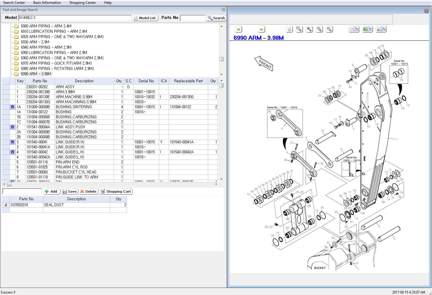
Understanding the visual representations of components is essential for efficient maintenance and repair tasks. These illustrations provide crucial insights into the assembly and structure of various mechanical systems. By familiarizing oneself with the elements depicted, users can identify necessary replacements and troubleshoot issues effectively.
1. Familiarize Yourself with Symbols: Each illustration uses specific symbols to denote different elements. Spend time studying these icons to understand their meanings. This knowledge will help you navigate the image with ease.
2. Pay Attention to Numbering: Components are often labeled with unique numbers. Cross-referencing these labels with accompanying documentation will enable you to locate the correct pieces quickly. Make sure to follow the sequence to avoid confusion.
3. Examine the Layout: The arrangement of elements can indicate how they interact within the assembly. Observe how components connect and their relative positions. This perspective is crucial when reassembling or disassembling parts.
4. Utilize Reference Guides: Many illustrations come with detailed reference guides or legends. These documents provide additional context and specifications. Always consult these resources for accurate information regarding dimensions and compatibility.
5. Practice with Real Examples: Hands-on experience can enhance your comprehension significantly. Use real components alongside the illustrations to reinforce your understanding. This practical approach can solidify your knowledge and improve your confidence in handling repairs.
By mastering these techniques, you will gain proficiency in interpreting visual representations of mechanical systems, ensuring efficient and accurate maintenance processes.
Identifying Part Numbers and Symbols
Understanding component identifiers and their corresponding symbols is essential for effective maintenance and repairs. These identifiers provide critical information about each individual element, ensuring proper selection and compatibility during replacement or service. Familiarity with these conventions can significantly enhance the efficiency of troubleshooting and repair processes.
When navigating the documentation for equipment, it is important to recognize the common formats and notations used to represent each item. Here are some key aspects to consider:
- Part Numbers: Typically consist of a combination of letters and numbers that convey specific details about the component, such as its size, type, and material.
- Symbols: Visual representations used to denote functions, connections, or specifications of different parts. Understanding these can aid in comprehending the assembly and operation of equipment.
To effectively interpret identifiers and symbols, users should familiarize themselves with the following guidelines:
- Refer to the provided manuals or reference materials for the correct identification of components.
- Pay attention to the format of the identifiers, as they often follow specific conventions that can indicate the type and purpose of the component.
- Consult with experienced technicians or refer to online resources for clarification on ambiguous symbols or notations.
By mastering the identification of component numbers and symbols, operators can ensure they select the correct items for maintenance tasks, thereby optimizing performance and longevity.
Benefits of Using Diagrams for Repairs
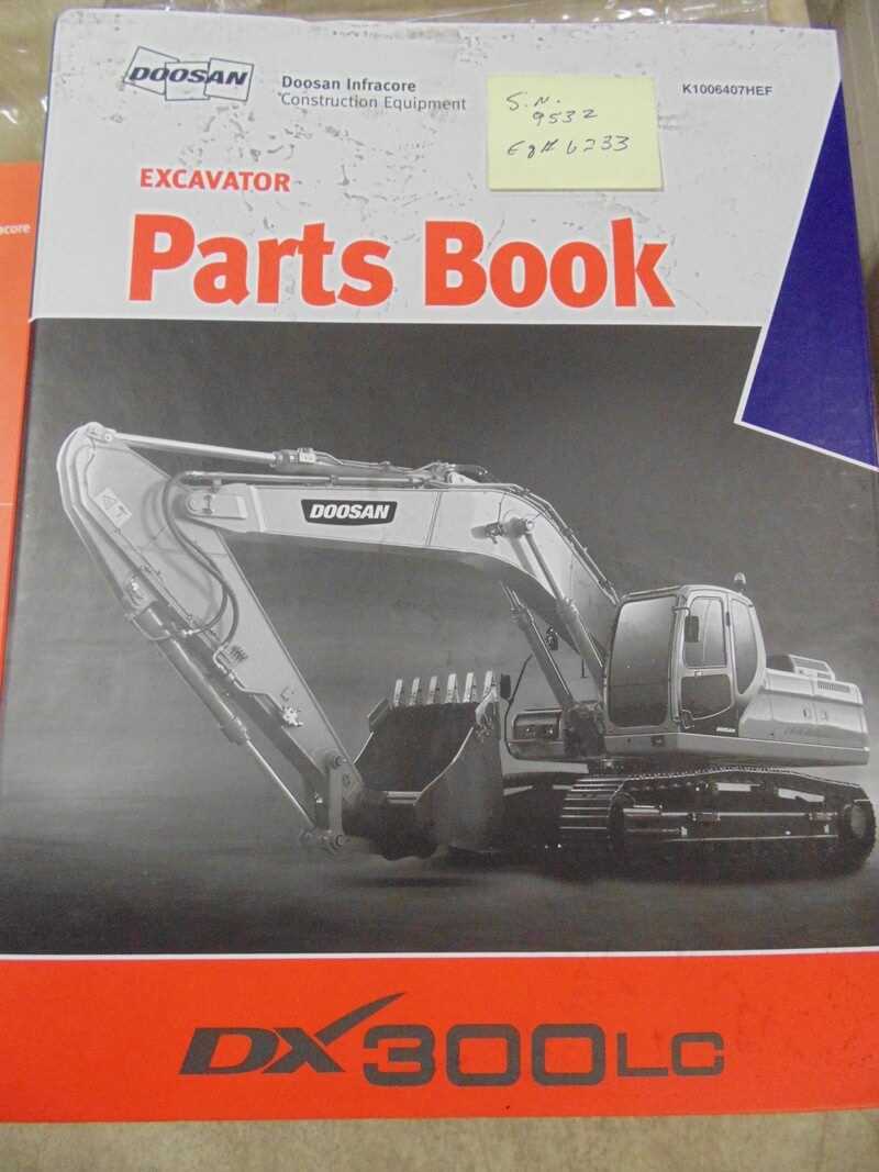
Utilizing visual representations during maintenance tasks can significantly enhance the efficiency and effectiveness of the repair process. These illustrations serve as invaluable tools, simplifying complex information and guiding technicians through intricate procedures. By relying on these resources, repair professionals can minimize errors, save time, and achieve higher-quality outcomes.
Enhanced Clarity and Understanding
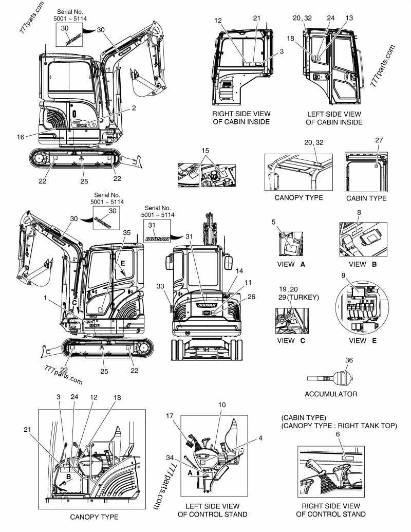
Visual aids provide clear representations of components and assemblies, making it easier to comprehend their functions and relationships. This clarity contributes to more accurate diagnostics and effective problem-solving. Key advantages include:
- Simplification of intricate processes
- Reduction of misinterpretations
- Visual guidance for assembling or disassembling units
Time and Cost Efficiency
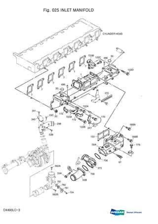
Implementing visual resources can lead to significant savings in both time and money. The benefits of time efficiency include:
- Quicker identification of issues
- Streamlined repair procedures
- Decreased need for repeated repairs due to improved accuracy
Incorporating these visual aids into the maintenance workflow not only fosters a more organized approach but also empowers technicians to work with greater confidence and precision.
Doosan Parts Diagram for Maintenance
Understanding the layout and components of heavy machinery is essential for effective upkeep and optimal performance. A well-organized visual representation of the various elements facilitates maintenance tasks, ensuring that operators can quickly identify and address issues as they arise. By familiarizing oneself with this schematic, one can streamline procedures, reduce downtime, and enhance the longevity of equipment.
Regular maintenance relies on an in-depth comprehension of each component’s role within the larger system. This knowledge allows technicians to execute repairs and replacements efficiently. Furthermore, recognizing the interconnectedness of parts aids in diagnosing potential problems before they escalate into significant failures.
Utilizing a detailed illustration not only promotes a proactive approach to service but also empowers personnel with the confidence to tackle challenges independently. Such resources serve as valuable references, guiding users through complex processes and ensuring all tasks are performed accurately.
In conclusion, leveraging comprehensive schematics significantly enhances maintenance efforts, fostering a culture of care and diligence in machinery operation. Proper understanding and application of these resources contribute to a safer and more efficient working environment.
Where to Find Doosan Diagrams Online
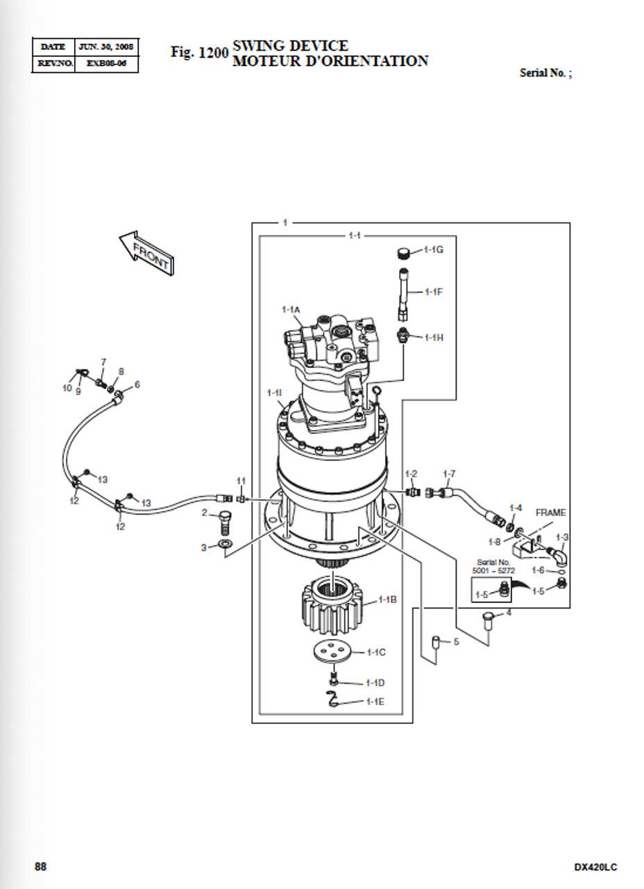
Locating technical illustrations and schematics can be crucial for understanding machinery and equipment functionality. The availability of detailed visual references can aid in maintenance, repair, and troubleshooting processes. Here are some reliable resources to help you find these essential documents online.
- Official Manufacturer Websites: Many manufacturers host a library of illustrations on their official platforms. Look for sections dedicated to resources or support.
- Online Forums and Communities: Participating in industry-specific forums can connect you with other users who may share valuable resources or links to visual aids.
- Third-Party Retailers: Various online retailers that specialize in equipment parts often provide access to schematics as part of their service.
- Technical Documentation Websites: Websites dedicated to technical documents frequently house a collection of diagrams and other useful references.
By exploring these avenues, you can effectively access the necessary illustrations to support your equipment maintenance and repair efforts.
Comparing Doosan Diagrams with Competitors
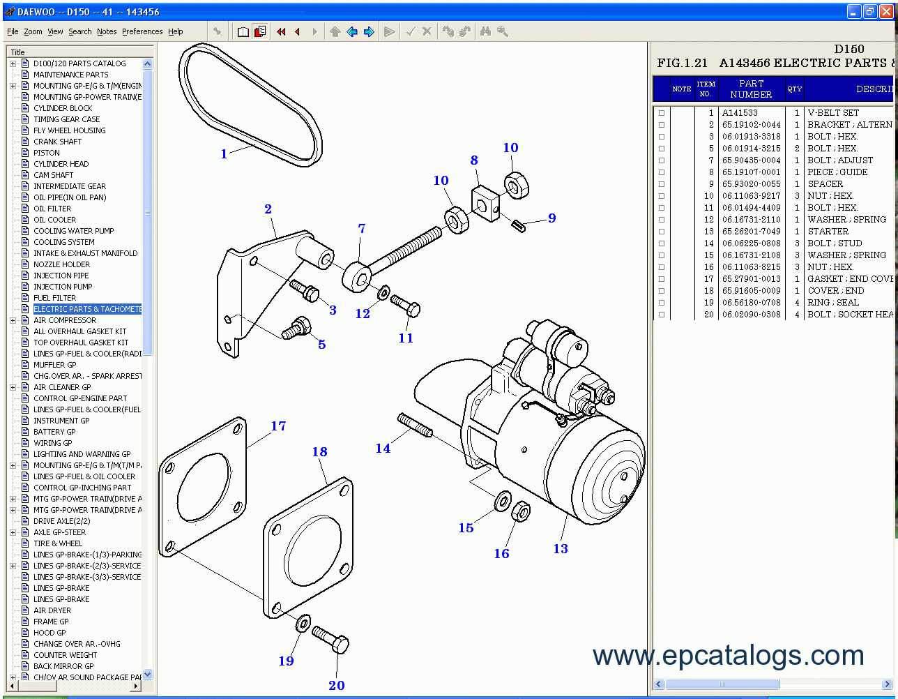
The analysis of visual representations in machinery can reveal significant insights into design efficiency and functionality. When examining the schematics provided by different manufacturers, it becomes clear that variations in clarity, detail, and organization can impact the user experience and operational effectiveness.
Clarity is a crucial factor when evaluating these visual aids. Some brands excel in presenting straightforward illustrations that facilitate quick understanding, while others may present complex layouts that require extensive familiarity with the equipment. This clarity can influence maintenance times and the ease with which technicians can navigate repair processes.
Detail plays another vital role. Certain manufacturers offer comprehensive breakdowns, highlighting every component, whereas others may provide only essential parts, leaving out minor yet important elements. A more detailed illustration allows for better troubleshooting and enhances the overall service experience.
Furthermore, the organization of these visuals varies widely. Some companies prioritize logical grouping and intuitive layouts, making it easier for users to locate specific components. In contrast, less organized formats can lead to confusion and extended downtime during maintenance, ultimately affecting productivity.
In summary, a thorough comparison of visual representations across various brands reveals that not only the quality of the visuals but also their clarity, detail, and organization are essential factors that can significantly affect user experience and operational efficiency.
Common Mistakes in Parts Identification
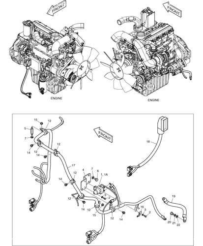
Accurate identification of components is crucial in various fields, particularly in machinery maintenance and repair. However, professionals often encounter pitfalls that can lead to errors, resulting in delays and increased costs. Understanding these common errors can significantly improve efficiency and reduce misunderstandings in the process.
One prevalent mistake involves relying solely on visual characteristics. While appearance can provide valuable clues, it may not always reflect the precise specifications or functionality required. Thus, comprehensive knowledge of technical details is essential for correct identification.
Another frequent issue is the failure to consult up-to-date reference materials. Outdated information can lead to misidentification of components, particularly as manufacturers release new models or updates. Ensuring access to the latest manuals and resources is vital for accurate assessments.
In addition, overlooking compatibility is a significant error. Two components may seem similar but may not function interchangeably due to subtle differences in design or performance criteria. Always verifying compatibility with the specific model is essential to avoid malfunctions.
Lastly, neglecting the importance of context in identification can lead to misunderstandings. A component’s role may vary depending on its application within a system. Understanding the overall operation and purpose of each element is crucial for accurate recognition and utilization.
Future Trends in Machinery Parts Documentation
The evolution of documentation for machinery components is poised to undergo significant transformation driven by technological advancements and changing industry demands. This shift will not only enhance accessibility and efficiency but will also promote better collaboration among stakeholders. Embracing innovative approaches will allow for streamlined processes and improved maintenance practices.
Integration of Digital Technologies

The future of documentation will increasingly rely on digital solutions to facilitate real-time updates and easy access to information. Key trends include:
- Cloud-based Systems: Storing data in the cloud ensures that all relevant parties can access the latest information from anywhere, improving coordination and reducing downtime.
- Augmented Reality (AR): Utilizing AR applications will allow technicians to visualize components in 3D, enabling more efficient troubleshooting and maintenance procedures.
- Blockchain Technology: This will provide a secure and transparent method for tracking the history of components, enhancing trust among manufacturers and users.
Enhanced User Experience
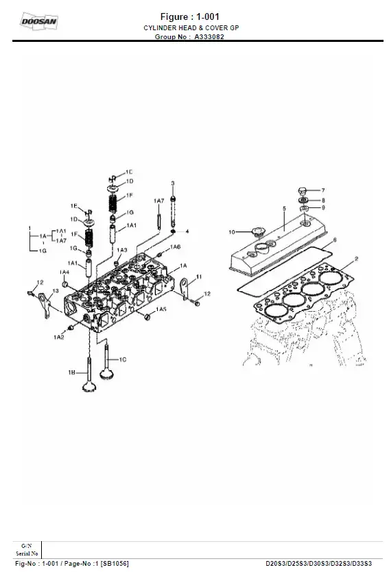
To cater to the evolving needs of users, documentation will focus on creating intuitive and user-friendly interfaces. Important elements include:
- Interactive Manuals: Incorporating multimedia elements such as videos and animations to provide comprehensive guidance on assembly and repair.
- Customization Options: Allowing users to tailor the information they receive according to their specific needs and preferences.
- Artificial Intelligence: AI-driven tools will assist users in quickly finding relevant information and troubleshooting issues, significantly reducing response times.
These trends highlight the importance of adapting documentation practices to meet the demands of a rapidly changing environment, ensuring that all stakeholders can effectively collaborate and maintain machinery with ease.