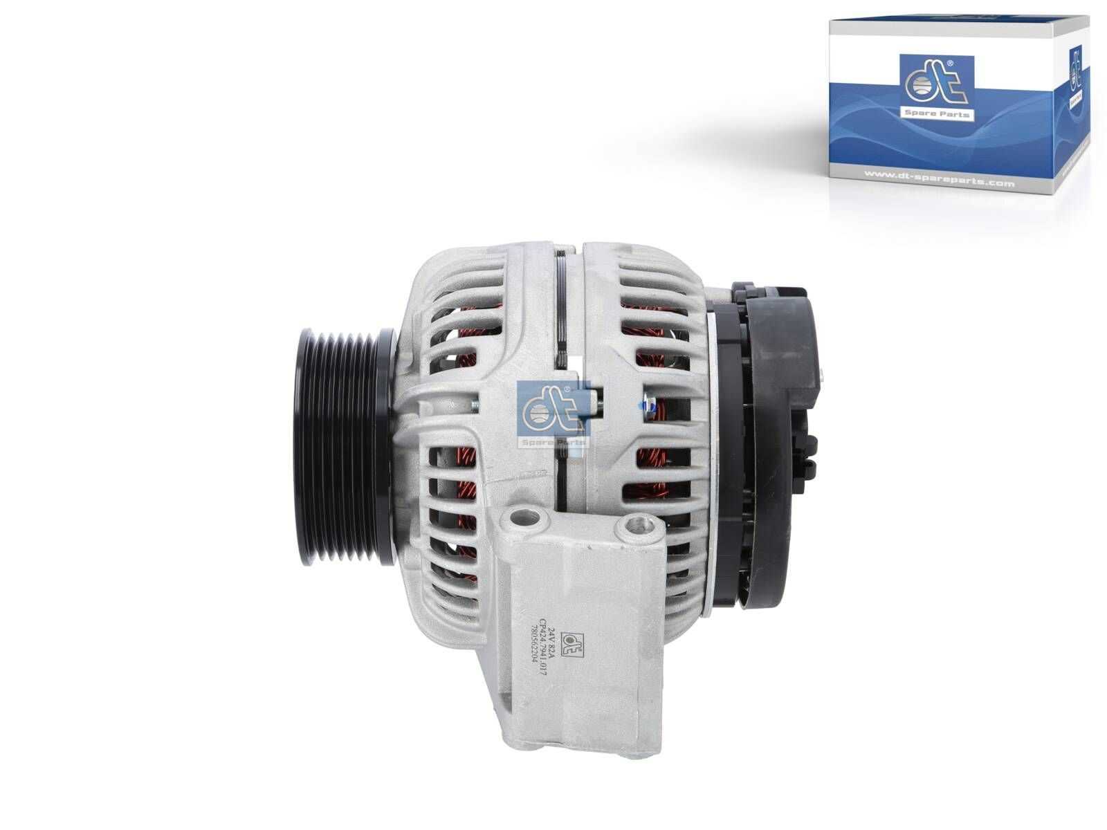
Understanding the structure and function of essential elements within automotive electrical systems is crucial for ensuring optimal performance. Each unit plays a specific role, working together to manage and distribute electrical energy throughout the vehicle. By exploring these interconnected elements, we gain a clearer picture of how energy flow is maintained, and how to troubleshoot common issues effectively.
One of the critical units in a vehicle’s power management system is responsible for converting mechanical motion into electrical energy. This energy is then used to support various electrical functions, from powering lights to keeping the battery charged. Knowing the internal workings of this system, including the identification and purpose of each internal part, is key to diagnosing performance issues and maintaining efficiency.
In this guide, we will walk through the main components of this essential device, breaking down each element and explaining its role within the larger system. Whether you’re looking to repair or simply understand how this mechanism operates, this detailed breakdown will provide you with the knowledge needed for proper maintenance and troubleshooting.
Bosch Alternator Component Breakdown
The mechanism at hand consists of various interconnected elements, each serving a specific function to ensure efficient energy conversion and system reliability. By understanding how these individual elements interact, we can grasp how the entire assembly works as a cohesive unit. This breakdown will help clarify the role of each part within the system.
Key Internal Elements
- Rotor: This central piece rotates within the assembly, generating a magnetic field that drives the electrical process.
- Stator: Surrounding the rotor, this stationary component harnesses the magnetic field to produce electric current.
- Diode Assembly: Converts alternating current (AC) generated by the stator into direct current (DC), which is essential for charging and powering electrical components.
Supportive Components
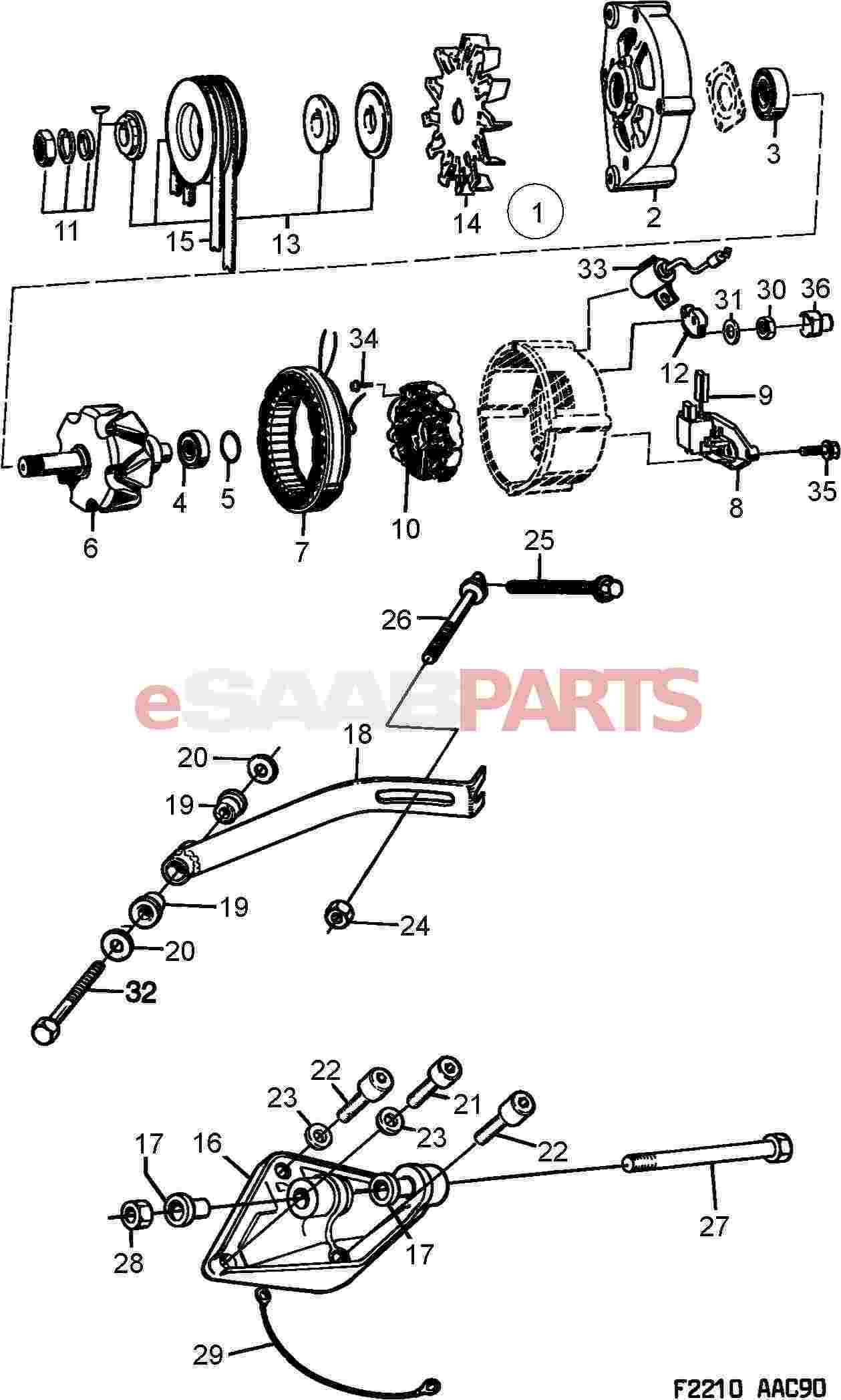
- Voltage Regulator: Maintains output consistency by regulating the electrical flow
Understanding the Internal Parts of a Bosch Alternator
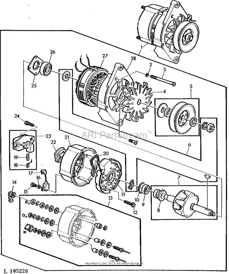
To comprehend how this essential automotive component functions, it’s crucial to familiarize oneself with the various elements that make up its inner workings. Each part plays a significant role in converting mechanical energy into electrical power, ensuring that the electrical systems operate efficiently. The collaboration of these components allows for the smooth operation of vehicles by maintaining a steady supply of current.
At the heart of this system lies the rotor, which rotates to create a magnetic field. Surrounding it is the stator, a stationary coil where electrical energy is induced. These two key elements interact to produce the necessary current. The voltage regulator ensures that the generated power is consistent and doesn’t fluctuate excessively, protecting the electrical system from damage.
Another integral element is the rectifier, responsible for converting alternating current (AC) into direct current (DC), which is necessary for most vehicle electronics. Cooling fans are also present
How Bosch Alternators Generate Electrical Power
The process of converting mechanical energy into electricity relies on the interaction between magnetic fields and electrical conductors. This system is designed to transform rotational motion into a continuous flow of electrical current, which is essential for powering various components. The principles of electromagnetic induction ensure that the generated electricity is both efficient and reliable, meeting the demands of modern electrical systems.
At the heart of this energy conversion process lies a rotating coil situated within a magnetic field. As the coil spins, it cuts through the magnetic lines of force, inducing an electrical current in the winding. This current is then captured and directed through a set of conductive paths, ultimately supplying energy to the system’s electrical needs.
The rotation of the coil is typically driven by the mechanical power from an engine, ensuring that the system operates continuously while the engine is running. A set of rectifiers is used to convert the generated alternating current (AC) into direct current (DC), which is required for most electronic components. Voltage regulation is another critical aspect, ensuring that the output remains stable and consistent despite varying operating conditions.
By using durable materials and precise engineering, the overal
Key Differences in Bosch Alternator Designs
Electrical generation systems for vehicles have evolved over time, with different manufacturers focusing on unique aspects of performance, efficiency, and reliability. Variations in design have resulted in several configurations that cater to distinct needs, including power output, durability, and application-specific features. Understanding these differences is crucial for choosing the right system for your vehicle’s requirements.
One of the primary distinctions lies in the structural layout. Some designs prioritize compactness to accommodate smaller engine compartments, while others are engineered for larger, high-output systems, often used in industrial or heavy-duty settings. Additionally, the cooling mechanisms vary significantly, with some models employing air-cooling and others utilizing liquid-based systems for enhanced thermal management under demanding conditions.
Electrical regulation also presents key variations. Certain models feature built-in regulators for maintaining consistent output, regardless of engine speed or load conditions, while others rely on external components for this function. These differences impact not only the overall efficiency but also the lifespan of the unit.
Finally, the materials used in construction can vary, influencing both the durability and weight of the unit. From lightweight aluminum housings to more robust steel frameworks, the choice of materials aff
Common Signs of Bosch Alternator Wear
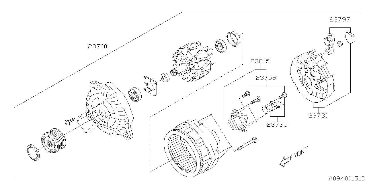
When a key electrical component in a vehicle begins to deteriorate, it can manifest in various noticeable ways. Being aware of these symptoms helps prevent further damage to other systems and avoids potential breakdowns. Recognizing early indicators of wear can lead to timely maintenance, extending the life of the entire charging system.
Dim or Flickering Lights – One of the first signs of trouble often involves the vehicle’s lights. If headlights or dashboard indicators appear weaker than usual, or flicker intermittently, it may indicate that the power generation system is struggling to meet the electrical demands of the car.
Slow Engine Crank – A weakening power source can cause difficulty when starting the vehicle. The engine might crank slower than normal, especially during colder weather, due to insufficient energy delivery to the starter.
Strange Noises – Unusual sounds, such as grinding or whining, can signal internal damage. These noises may stem from worn bearings or
How to Identify Bosch Alternator Models
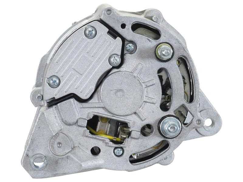
Understanding the various models of electrical generators is essential for effective maintenance and repair. Each unit comes with distinct features and specifications that can aid in identifying its model. Knowing these characteristics can streamline the process of selecting compatible components and ensure optimal performance.
First, examine the identification numbers found on the generator’s casing. These alphanumeric codes are crucial for determining the model and can often be located near the mounting brackets or on a label. It is advisable to document these numbers as they can simplify the search for replacements or technical support.
Next, analyze the physical attributes of the device. Take note of the overall size, shape, and design of the housing. Variations in these aspects can be indicative of specific models. Additionally, check the number of terminals and their arrangement, as different versions may feature distinct configurations.
Furthermore, consult the manufacturer’s catalog or online resources to cross-reference the gathered information. Many suppliers offer databases that allow for the identification of models based on the previously mentioned details. Utilizing these tools can significantly reduce the time spent on identifying the correct unit.
Finally, if uncertainty remains, consider reaching out to professionals or forums specializing in electrical equipment. Experienced individuals in these communities can provide insights or additional resources that may facilitate accurate identification.
Detailed Overview of Voltage Regulation in Bosch Alternators
The functionality of a generator relies heavily on its ability to maintain a consistent output level despite fluctuations in demand. The voltage control mechanism plays a pivotal role in ensuring that the electrical system remains stable and efficient, thus preventing potential damage to connected components. This overview delves into the intricacies of how voltage regulation is achieved in these systems, focusing on the components and principles involved in the process.
Key Components of Voltage Regulation
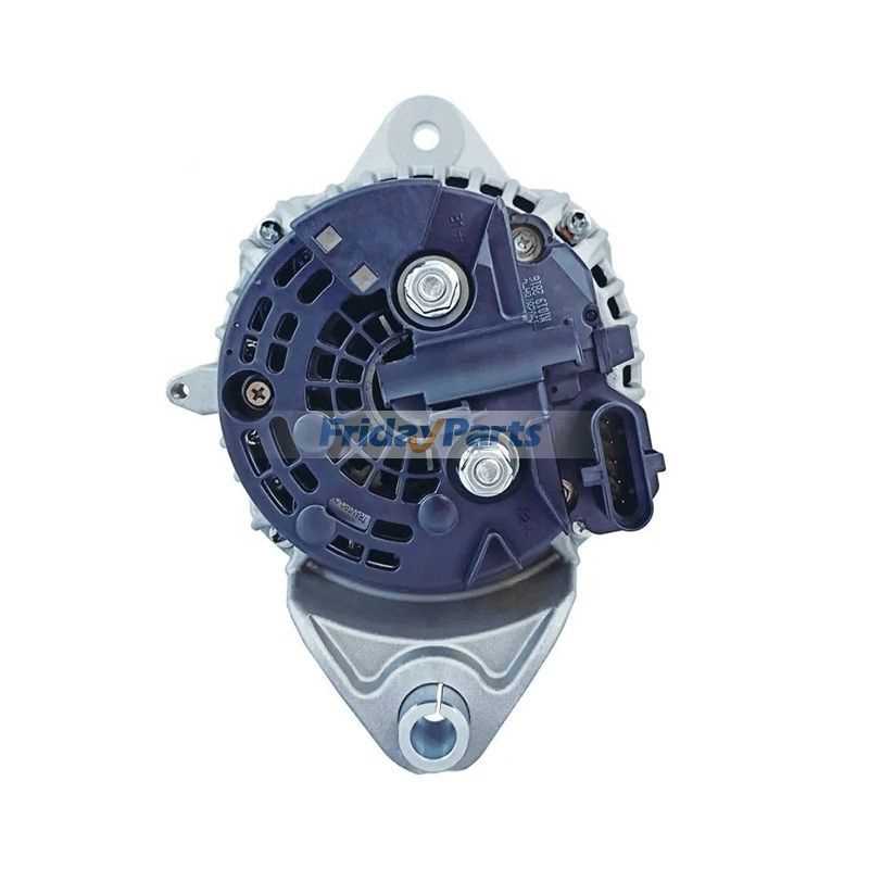
At the heart of the voltage management system lies the regulator, which continuously monitors and adjusts the output. Typically, this device operates by comparing the actual voltage level to a predetermined setpoint. When deviations occur, the regulator makes real-time adjustments to rectify the situation. The primary components involved include the voltage sensor, which detects voltage levels, and the control unit, which processes this information and modifies the excitation current accordingly.
Regulation Mechanism and Functionality
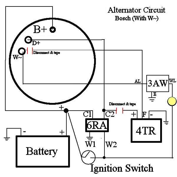
The regulation mechanism operates through a feedback loop, where the sensor relays data to the control unit. This unit determines whether the output is above or below the desired threshold. If the voltage is too high, the regulator decreases the excitation current, reducing the magnetic field strength and subsequently lowering the voltage output. Conversely, if the output is insufficient, the regulator increases the excitation, thereby enhancing the magnetic field and elevating the voltage. This dynamic adjustment ensures a reliable and efficient power supply, vital for optimal performance.
In conclusion, understanding the voltage regulation process is crucial for maintaining the reliability of electrical systems. The interplay of various components ensures that voltage levels are kept within safe limits, protecting the integrity of the entire electrical infrastructure.
Functions of the Bosch Alternator Rotor and Stator
The inner workings of a generator rely on two key components: the rotating element and the stationary element. Each plays a crucial role in the generation of electrical energy, contributing to the overall efficiency and functionality of the system. Understanding their specific functions provides insight into how they convert mechanical energy into electrical power, which is vital for the operation of various devices.
Role of the Rotating Element
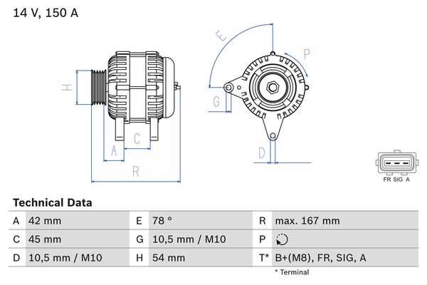
The rotating element is responsible for creating a magnetic field as it spins within the assembly. This movement induces an electromotive force (EMF) in the stationary component through electromagnetic induction. The speed of rotation directly affects the strength of the generated current, making this component essential for optimal performance. Additionally, the rotor is often equipped with windings that enhance its magnetic properties, further improving energy production.
Role of the Stationary Element
The stationary element acts as the main site for energy conversion. It contains windings that capture the magnetic field produced by the rotating part and convert it into electrical energy. This component’s design is crucial, as it must efficiently transfer the induced current to the electrical system while minimizing losses. Furthermore, the stationary element often includes rectifiers to ensure that the current produced is suitable for the intended applications, thereby maintaining system stability and reliability.
The Role of Rectifiers in Bosch Alternators
Rectifiers serve a critical function in converting alternating current into direct current, ensuring the effective operation of electrical systems in vehicles. This process is essential for maintaining consistent power supply, which supports various electronic components.
In automotive applications, the significance of rectifiers can be understood through several key aspects:
- Current Conversion: Rectifiers transform the AC generated by the rotor into DC, making it suitable for powering batteries and other electrical circuits.
- Efficiency: High-quality rectifiers enhance the overall efficiency of the power generation system, minimizing energy loss and heat production.
- Stability: By providing a steady voltage output, rectifiers help stabilize the electrical system, preventing fluctuations that could damage sensitive components.
There are two main types of rectifiers used in these systems:
- Half-wave Rectifiers: These devices allow only one half of the AC cycle to pass through, resulting in less efficient conversion.
- Full-wave Rectifiers: These are more common, as they utilize both halves of the AC cycle, offering improved performance and reliability.
In summary, rectifiers are indispensable components that facilitate the efficient and stable operation of vehicle electrical systems, highlighting their importance in modern automotive technology.
Guide to Replacing Bosch Alternator Brushes
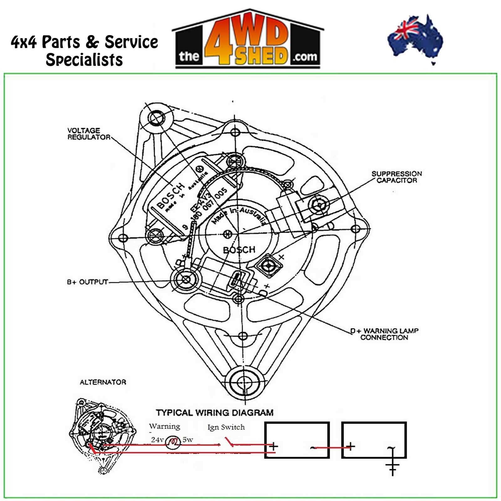
Maintaining the efficiency of your electrical charging unit is essential for the overall performance of your vehicle. Over time, the contact components can wear out, leading to reduced functionality and potential failure. This guide provides a detailed overview of the steps involved in replacing the brushes in your electrical device, ensuring optimal operation and longevity.
Understanding the Importance of Brushes

The brushes play a critical role in the operation of your device by conducting electricity between the stationary and rotating parts. When they become worn or damaged, they can lead to poor performance, including intermittent power loss or complete failure to charge. Regular inspection and timely replacement of these components are vital to prevent more significant issues.
Steps for Replacement
1. Gather Your Tools: You will need a screwdriver, a set of replacement brushes, and a multimeter to test the functionality.
2. Disconnect the Battery: Safety first; always disconnect the power source before performing any maintenance.
3. Access the Unit: Remove the housing carefully, ensuring not to damage any other components.
4. Remove Old Brushes: Identify the worn brushes and carefully detach them from their holders. Take note of their positioning for accurate reinstallation.
5. Install New Brushes: Position the new components in the same orientation as the old ones, ensuring a secure fit.
6. Reassemble and Test: After replacing the brushes, reassemble the unit and reconnect the battery. Use a multimeter to verify proper functionality before finalizing the installation.
By following these steps, you can effectively replace the brushes, contributing to the reliability and efficiency of your vehicle’s electrical system.
How to Troubleshoot Bosch Alternator Malfunctions
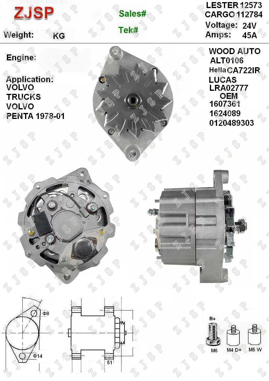
Identifying issues with your vehicle’s electrical system can be a daunting task. It is essential to recognize signs of dysfunction to ensure optimal performance. This section outlines effective strategies for diagnosing problems associated with the charging unit, helping you to pinpoint the root cause of malfunctions and restore efficiency.
Common Symptoms of Electrical System Issues
- Dim or flickering lights
- Difficulty starting the engine
- Unusual noises when the engine is running
- Warning lights on the dashboard
- Frequent battery drain
Step-by-Step Troubleshooting Guide
- Visual Inspection: Begin with a thorough examination of the electrical components. Look for signs of wear, loose connections, or corrosion.
- Check Battery Condition: Ensure the battery is in good condition and properly charged. A weak battery can mimic issues with the charging system.
- Test Voltage Output: Use a multimeter to measure the voltage at the terminals. A reading below the expected range indicates potential issues.
- Examine Connections: Inspect all wiring and connectors for damage or disconnection, as these can significantly impact functionality.
- Seek Professional Help: If the problem persists after basic troubleshooting, consider consulting a specialist for a detailed inspection and repair.
Maintenance Tips for Extending Bosch Alternator Lifespan
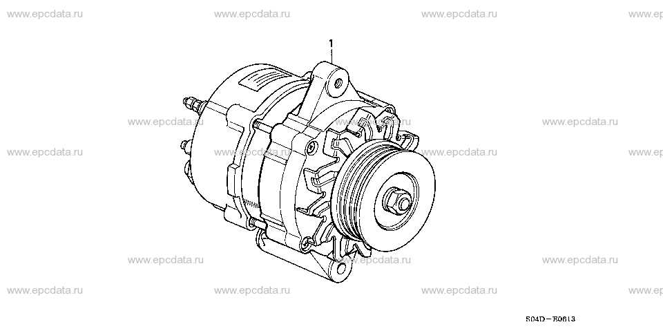
Regular care and attention are essential for maximizing the operational lifespan of critical electrical components in vehicles. By following best practices and conducting routine inspections, you can significantly enhance their durability and performance. This section provides actionable strategies for ensuring your electrical systems remain efficient and reliable.
1. Keep It Clean: Accumulation of dirt and debris can lead to overheating and decreased efficiency. Regularly inspect and clean the exterior of the device to prevent contaminants from entering its internal components.
2. Monitor Electrical Connections: Loose or corroded connections can hinder performance and create unnecessary strain. Periodically check all electrical links, ensuring they are tight and free from oxidation.
3. Check Voltage Output: Maintaining the correct voltage is crucial for optimal functionality. Use a multimeter to regularly measure the output voltage and ensure it falls within the recommended range.
4. Avoid Overloading: Ensure that the electrical load does not exceed the recommended specifications. Overloading can cause premature failure, so be mindful of the number of devices powered simultaneously.
5. Address Issues Promptly: Any signs of malfunction–such as unusual noises or flickering lights–should be investigated immediately. Early detection of problems can prevent more extensive damage and costly repairs.
6. Schedule Professional Inspections: Regular assessments by a qualified technician can identify potential issues before they escalate. Schedule these inspections to maintain overall system health and longevity.
7. Ensure Proper Ventilation: Adequate airflow is essential to dissipate heat generated during operation. Ensure that the installation area is well-ventilated and free from obstructions.
Implementing these maintenance strategies will help prolong the lifespan of your electrical components, ensuring they continue to function effectively over time.
Steps to Install a New Bosch Alternator
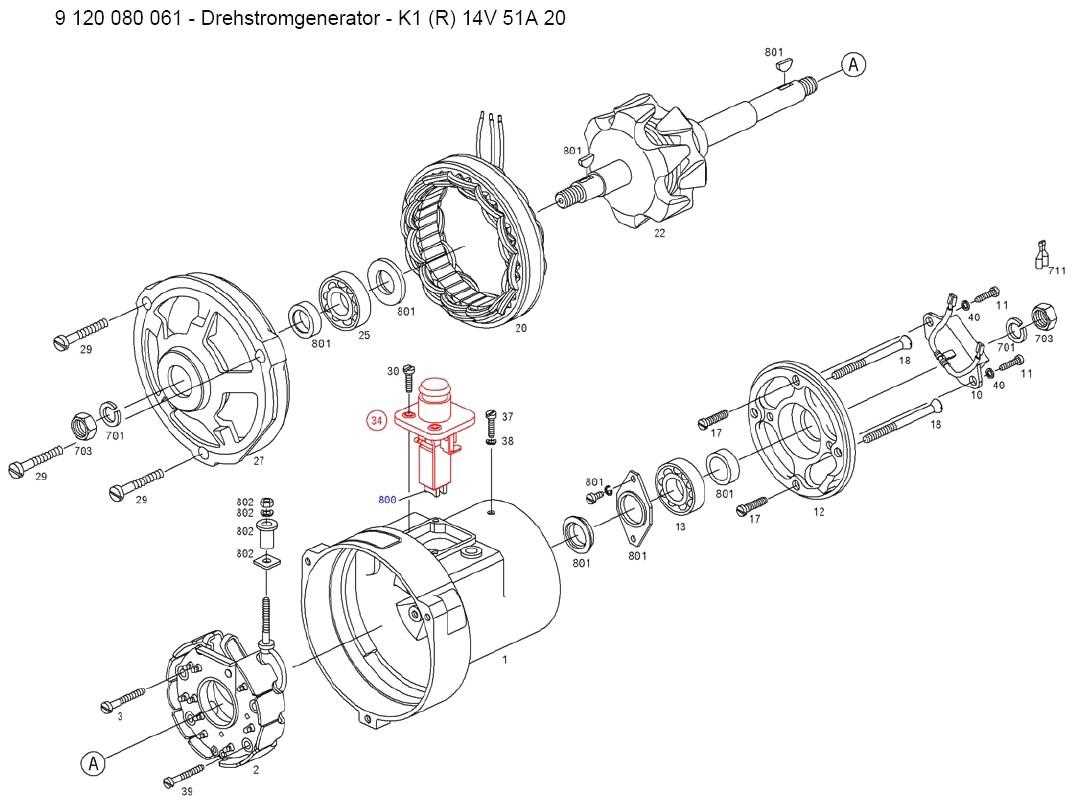
Replacing a vital component of your vehicle’s charging system can seem daunting, but with careful preparation and attention to detail, the process can be straightforward. This guide outlines the essential steps to ensure a smooth installation, helping you restore your vehicle’s electrical functionality.
Preparation Before Installation
Before you begin, it’s crucial to gather the necessary tools, including wrenches, screwdrivers, and a socket set. Additionally, consult your vehicle’s manual to understand the specific requirements for the component being replaced. Ensure the engine is turned off and cooled down to prevent any injuries. Disconnect the negative battery terminal to eliminate any risk of electrical shock.
Installation Process
Start by removing the old unit. Loosen the mounting bolts and carefully detach any connecting wires. Once the component is out, inspect the mounting area for any debris or damage. Next, position the new unit in place, aligning it with the mounting brackets. Secure it with the appropriate bolts, ensuring it is firmly attached. Reconnect the electrical connections, taking care to match each wire to its corresponding terminal. Finally, reattach the negative battery terminal and run the engine to test the new component’s functionality.
Tips: Double-check all connections and ensure there are no loose wires. If the unit does not function as expected, revisit each step to confirm proper installation.