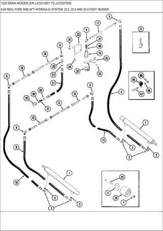
When working with agricultural machinery, it’s essential to have a clear overview of how each element interacts. Knowing the layout and configuration of various mechanical elements is crucial for efficient operation and timely maintenance. This understanding allows for smooth workflow and the prevention of potential breakdowns.
Every machine is composed of several key sections, each playing an important role in its overall functionality. By becoming familiar with these individual components, operators can ensure the longevity and reliability of their equipment. Detailed knowledge of the internal structure enables faster repairs and adjustments.
Additionally, being able to recognize the connections between these elements helps in planning regular servicing, ensuring peak performance in the field. With a well-maintained system, efficiency is maximized, and costly downtime can be avoided.
Understanding the Structure of the 1020 Header
The header is a crucial component designed to ensure efficient crop harvesting. Its primary function is to gather and direct the produce smoothly into the machinery, minimizing losses and enhancing performance. To fully understand its operation, it’s important to look at the various sections and how they work together to handle different types of crops and terrains.
Main Functional Areas
Each section of the header has a specific role. The gathering mechanism ensures that the crops are collected evenly, while the cutter bar works to efficiently trim plants close to the ground. Adjustable features allow the unit to adapt to varying field conditions, ensuring an optimal harvest in all scenarios.
Key Mechanical Components
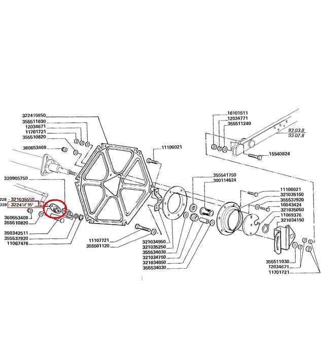
Several moving parts work in unison to achieve a smooth operation. The drive systems, along with rotating elements, ensure a consistent flow of material. These features reduce the need for manual intervention and contribute to the overall reliability of the equipment.
Main Components of the 1020 Series

The agricultural equipment in this series is known for its efficiency and durability, ensuring a smooth operation in various field conditions. The machinery is equipped with several key elements that work together to optimize harvesting performance, offering users both precision and reliability.
Key Structural Elements
- Cutting Platform: This section handles the initial phase of harvesting, carefully cutting crops with sharp, durable blades.
- Auger System: After cutting, the crops are efficiently transported for further processing through a well-designed rotating mechanism.
- Reel Mechanism: Assisting in the collection process, this component helps guide and position crops for smooth transition into the platform.
Support and Adjustment Features
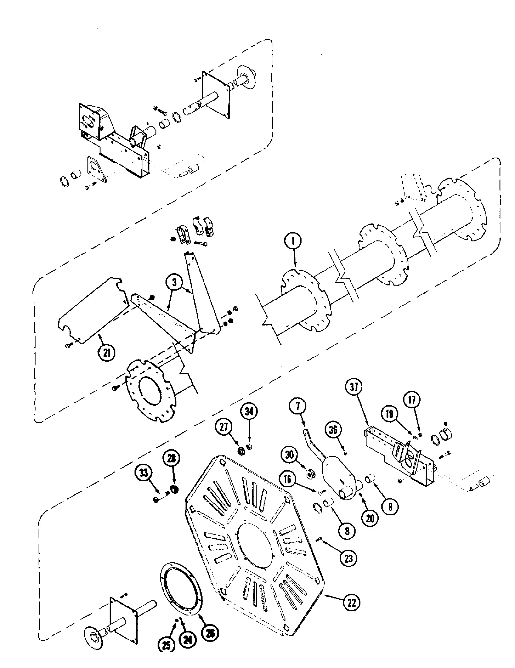
- Height Control: Adjustable systems allow for precise height regulation of the cutting platform to match varying field conditions.
- Skid Plates:
Drive System Overview for the IH 1020
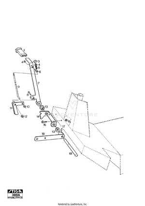
The drive system of this model is responsible for ensuring smooth and efficient operation. It powers key components that are crucial for proper functionality during harvesting. This section will provide insights into how the drive mechanism is structured, its main elements, and how it contributes to overall performance.
- Main Drive Mechanism: The primary drive transmits power from the engine to the operational parts, ensuring a steady flow of energy throughout the system.
- Belt and Pulley Arrangement: A series of belts and pulleys transfer power between different sections, helping to manage speed and torque for optimal functionality.
- Hydraulic System: Hydraulic components assist in adjusting and maintaining the correct pressure for the machinery’s moving parts, allowing for smooth transitions and adjustments.
Understanding the structure and key elements of this drive system helps operators maintain and troubleshoot it efficiently.
Cutting Mechanism and Its Parts
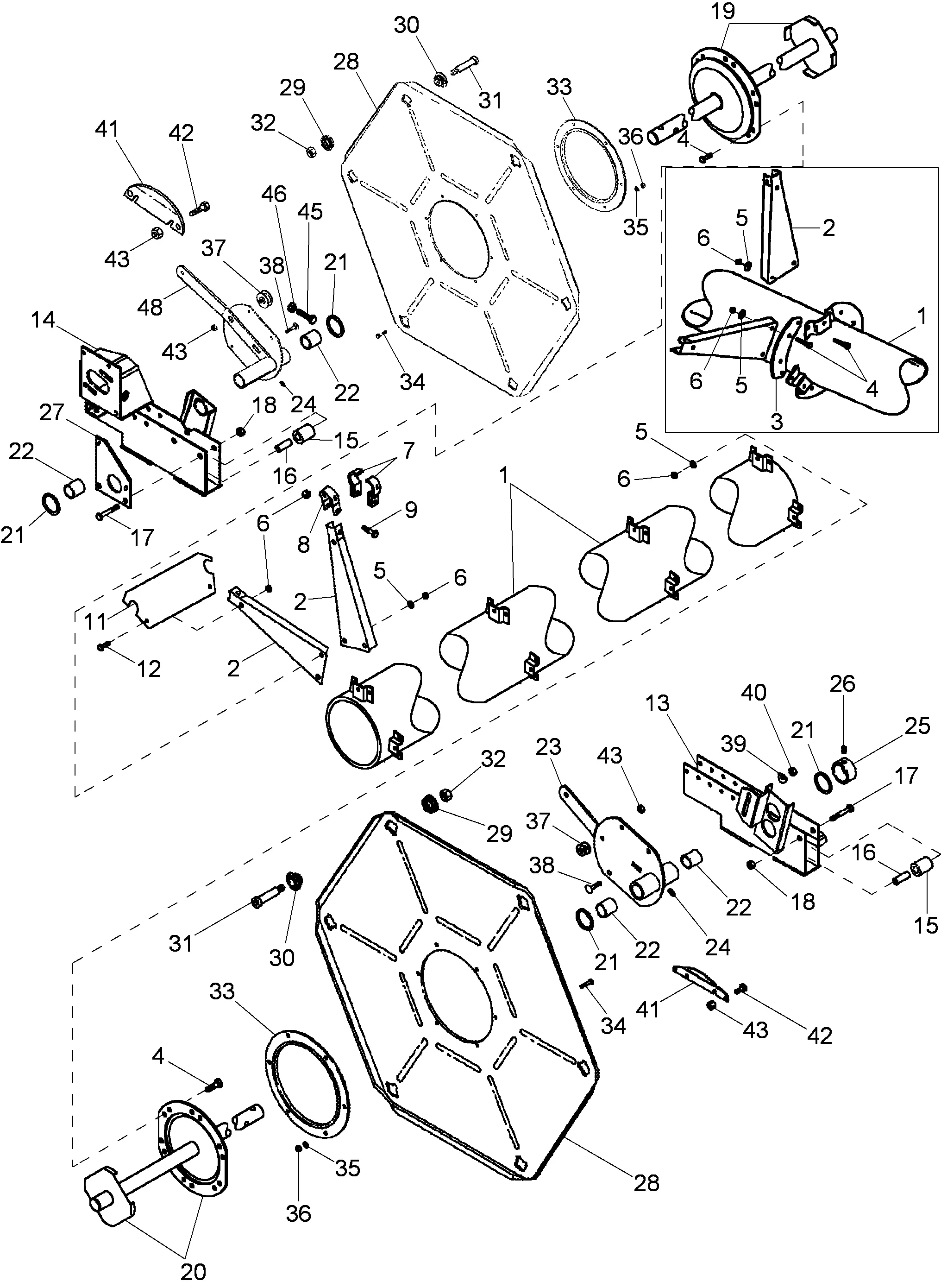
The cutting mechanism is a crucial component designed to efficiently manage the process of slicing through various materials during fieldwork. Its function revolves around ensuring smooth and continuous operation, which ultimately leads to enhanced productivity and precision in harvesting operations.
Key Elements of the Cutting System
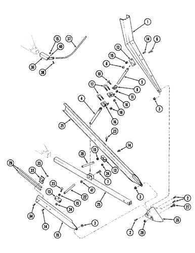
The main elements of this system are designed to work in harmony, offering both strength and flexibility. The blades are sharp and durable, allowing for precise cutting. Other components ensure the correct movement and alignment of the blades, facilitating smooth operation. Each part contributes to minimizing wear and ensuring the longevity of the mechanism.
Maintenance and Adjustments
Regular maintenance is essential to keep the system in top condition. Proper lubrication, periodic inspections, and timely replacements of worn-out elements help maintain efficiency. Adjustments might be required over time to ensure optimal performance and minimize potential breakdowns during heavy usage.
Component Auger Assembly Breakdown
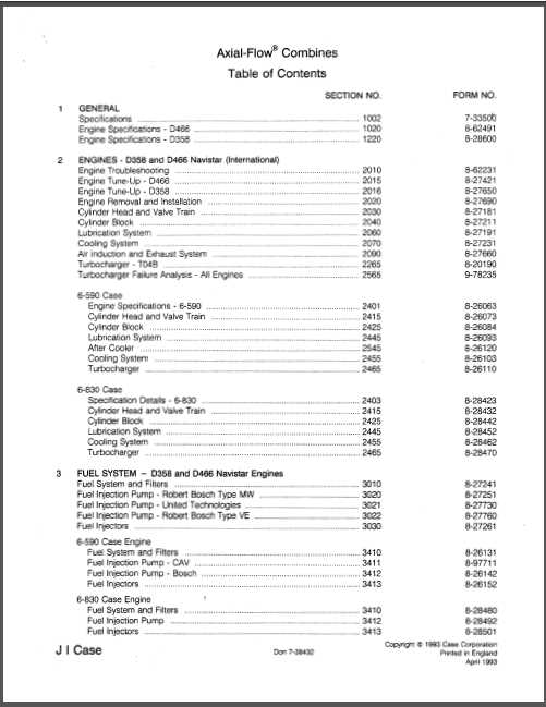
The auger mechanism plays a crucial role in the overall efficiency of harvesting equipment. It ensures smooth material flow, directing crops effectively to further processing. Understanding the various components within the auger system can aid in proper maintenance and optimal performance.
Main Components
- Auger shaft: The central axis that rotates, enabling the movement of materials.
- Flighting: The helical structure wrapped around the shaft, responsible for propelling the crop.
- Bearings: Positioned at key points to reduce friction and support rotation.
- Supports: Provide stability to the entire assembly, ensuring smooth operation.
Key Maintenance Tips
- Regularly inspect the flighting for wear or damage that could affect efficiency.
- Ensure bearings are well-lubricated to prevent overheating and reduce wear.
- Check the shaft alignment to avoid unnecessary strain on the auger components.
- Secure
How the Reel Functions in the 1020
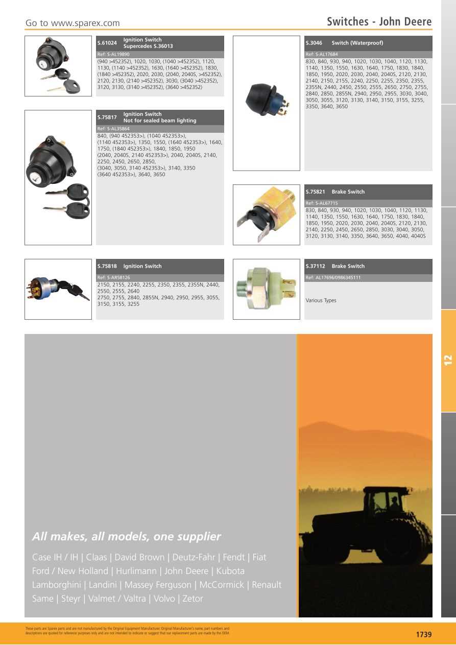
The reel plays a crucial role in the harvesting process, ensuring that crops are effectively gathered and fed into the machine. Its design and operation are tailored to optimize performance, contributing to the overall efficiency of the harvesting system. Understanding its mechanics is essential for maintaining smooth operation and enhancing productivity.
Components of the Reel
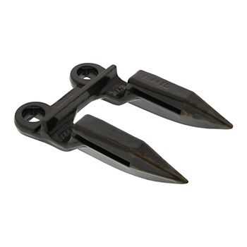
The assembly consists of several key elements that work together seamlessly. Each part is designed to perform a specific function, ensuring that the crop is drawn in efficiently and evenly. Here are the main components:
Component Function Fingers Help in grabbing the crop and directing it towards the cutter bar. Reel Arms Support the fingers and allow for height adjustments based on crop conditions. Drive Mechanism Provides motion to the reel, enabling it to rotate and engage the crop. Bearings Ensure smooth rotation of the reel arms and overall stability of the assembly. Operational Mechanics
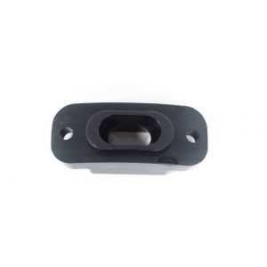
When the reel is engaged, it rotates in a manner that captures the crop as it approaches the cutting mechanism. The fingers extend and retract, allowing for an efficient gathering action. This dynamic movement ensures that the crop is not only collected but also aligned properly for optimal cutting and processing.
Hydraulic System Key Elements
The hydraulic system plays a crucial role in the efficient operation of agricultural machinery, providing the necessary power for various functions. Understanding its fundamental components is essential for ensuring optimal performance and maintenance.
Hydraulic Pump: This device converts mechanical energy into hydraulic energy, creating the pressure required to move fluid throughout the system. It is vital for initiating the hydraulic cycle.
Hydraulic Cylinders: These components are responsible for converting hydraulic energy back into mechanical energy, facilitating linear motion. They are commonly used for lifting and lowering equipment.
Hydraulic Hoses and Fittings: These elements transport hydraulic fluid between components, ensuring a seamless flow and maintaining system integrity. Proper selection and installation are critical to prevent leaks and ensure safety.
Control Valves: These devices regulate the flow and pressure of hydraulic fluid, allowing operators to control the speed and direction of movement. Their functionality directly impacts the overall efficiency of the system.
Fluid Reservoir: This component stores hydraulic fluid, ensuring a constant supply to the system. It plays a vital role in maintaining the required fluid levels and cooling the hydraulic fluid during operation.
Adjustment Points for Efficient Operation

Optimizing the performance of agricultural machinery involves careful consideration of various adjustment areas. These points play a crucial role in ensuring that the equipment operates at peak efficiency, ultimately enhancing productivity and reducing wear on components. Understanding how to fine-tune these settings can significantly impact overall effectiveness.
First and foremost, it is essential to regularly assess the calibration of the machine. Proper alignment and settings allow for smooth operation, which directly influences the quality of work. Ensuring that all moving parts are correctly adjusted prevents unnecessary strain and can lead to longer service intervals.
Moreover, regular inspections of critical components, such as the cutting mechanism and feed rate, are vital. Adjusting these elements based on specific operational conditions not only enhances performance but also optimizes fuel efficiency. Monitoring these factors closely helps to maintain consistent output and reduces operational costs.
In conclusion, paying attention to adjustment points can lead to substantial improvements in the functionality of the machinery. A proactive approach to managing these aspects is key to maximizing productivity and ensuring the longevity of the equipment.
Electrical Components and Their Placement
This section delves into the crucial aspects of electrical elements found within the machinery, focusing on their configuration and positioning. Understanding the arrangement of these components is essential for efficient operation and maintenance. Proper placement ensures optimal functionality and reliability during usage.
The electrical system typically includes various elements such as wiring harnesses, connectors, relays, and switches. Each component serves a specific purpose, contributing to the overall performance of the equipment. For instance, connectors facilitate seamless communication between different sections, while relays play a pivotal role in controlling power flow. Careful attention to their layout can prevent malfunctions and enhance safety during operation.
Moreover, recognizing the location of these electrical parts aids in troubleshooting and repair efforts. Familiarity with the arrangement allows technicians to quickly identify issues, ensuring minimal downtime. It is vital to refer to the manufacturer’s documentation for detailed insights into the specific positioning and specifications of these components, as variations may exist among different models.
Troubleshooting Common Part Failures
Understanding typical component malfunctions is essential for maintaining optimal functionality in agricultural machinery. Recognizing signs of wear or failure can prevent costly repairs and ensure smooth operations during critical periods.
Here are some common issues and their potential causes:
- Unusual Noises:
- Check for loose or damaged components.
- Inspect bearings for signs of wear.
- Poor Performance:
- Evaluate if any parts are obstructed or blocked.
- Ensure all connections are secure and functioning correctly.
- Leaking Fluids:
- Identify the source of the leak.
- Replace any worn seals or gaskets.
Regular maintenance can significantly reduce the risk of these failures. Implementing a routine inspection schedule allows for early detection of potential issues, ensuring longevity and efficiency of equipment.
- Unusual Noises: