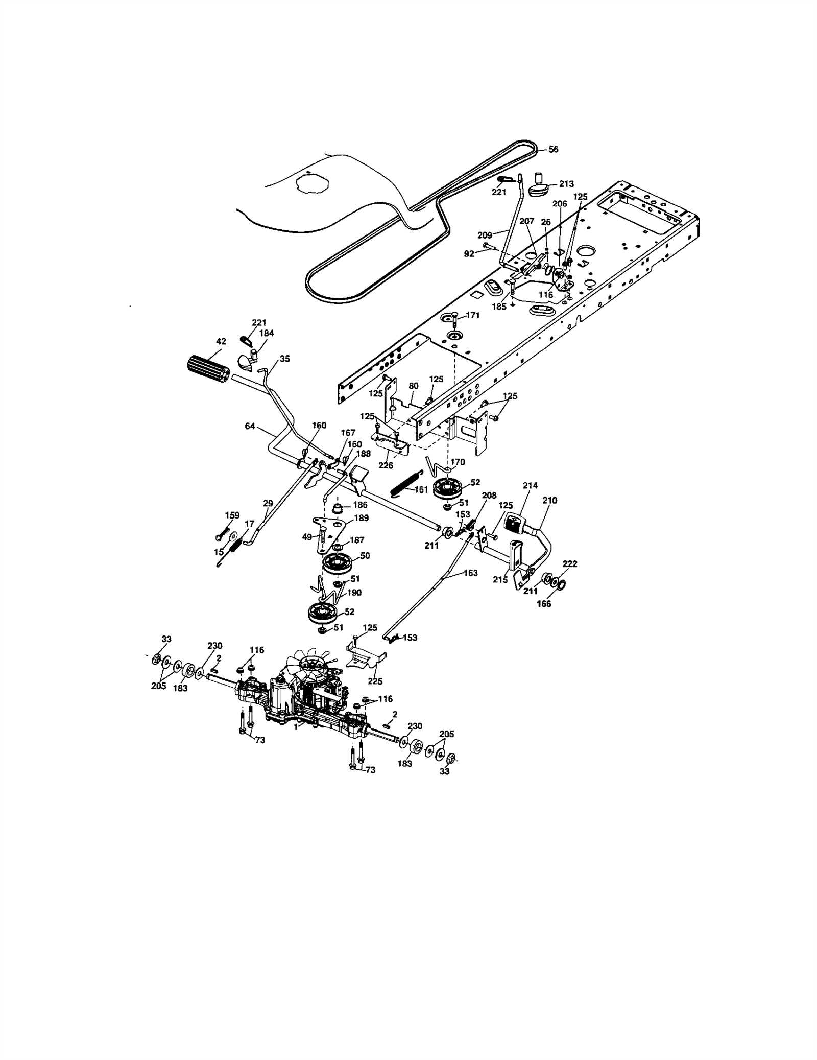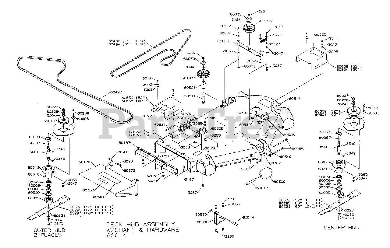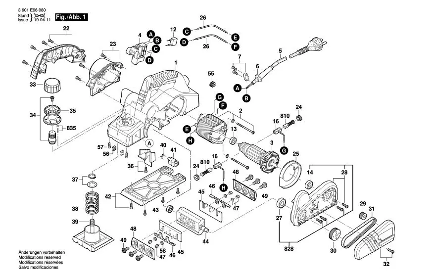
The detailed breakdown of various mechanical elements is essential for maintaining and repairing any machinery. Understanding how individual elements fit together and function as part of a larger system helps to ensure smooth operation and extend the equipment’s lifespan. This section offers an in-depth look at the assembly and structure of key components, enabling better insight into their roles and interactions.
Each part plays a crucial role in ensuring the overall performance and efficiency of the machine. Recognizing the purpose of each element and how they work in harmony is vital for troubleshooting and maintenance. This guide serves as a resource for identifying and understanding the primary components, facilitating smoother repairs and upgrades when needed.
Through this structured approach, we aim to provide clear and accessible information about the key elements involved in the overall operation. This will empower users to handle their machinery with greater confidence and precision, whether for general upkeep or in response to specific issues.
Understanding the Craftsman DGS 6500 Components
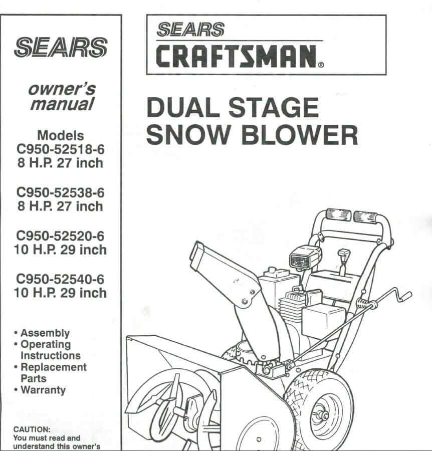
In this section, we will explore the essential components that make up this high-performance riding mower. Each part plays a crucial role in ensuring smooth operation, durability, and efficiency. By breaking down the main elements, you’ll gain a clearer understanding of how these pieces function together to maintain optimal performance in various conditions.
Engine and Transmission
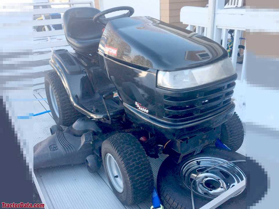
The power source is key to ensuring consistent performance. The engine provides the necessary force to drive the mower, while the transmission system allows for smooth adjustments in speed and direction. This interaction ensures that the machine can handle diverse terrains with ease.
Cutting Deck and Blades
The cutting deck houses the blades responsible for trimming grass to the desired height. Its design and material are critical for achieving an even cut, while the blades themselves must remain sharp and well-maintained to provide clean, efficient mowing. Together, these elements deliver precision and uniformity across your lawn.
| Component | Function | ||||||||||||
|---|---|---|---|---|---|---|---|---|---|---|---|---|---|
| Engine | Supplies power
Key Features of the DGS 6500 MowerThis mower is designed to provide an exceptional experience in lawn maintenance, offering durability, efficiency, and user-friendly operation. It stands out for its powerful capabilities and intuitive controls, making it a reliable choice for large areas. Below is an overview of its essential features, which ensure optimal performance and ease of use.
Engine Specifications and Performance OverviewIn this section, we will explore the essential features and capabilities of the engine, highlighting its efficiency and output. Understanding how these components work together ensures optimal performance, making the machine reliable and powerful in a variety of conditions. Power Output and CapacityThe engine is designed to deliver consistent power across various workloads. Its capacity allows for efficient fuel consumption while maintaining high levels of torque, ensuring smooth operation even under challenging tasks. The balance between power and fuel economy is a key factor that contributes to its long-lasting performance. Durability and MaintenanceThe engine’s construction incorporates high-quality materials that promote durability and longevity. Regular maintenance is straightforward, ensuring that key components remain in excellent working condition over time. This attention to detail not only extends the lifespan of the engine but also enhances its reliability in demanding environments. Exploring the Transmission System LayoutThe transmission system is a vital component that ensures efficient power transfer from the engine to the wheels. Its layout plays a crucial role in how the machine operates, controlling both speed and direction. Understanding this arrangement helps to maintain optimal performance, providing smooth transitions between various operational modes. By examining the system’s key elements, we can better appreciate how mechanical energy is distributed to achieve the desired movement. Key Components of the TransmissionThe primary elements within the transmission structure include the gearbox, which moderates speed, and the drive belts that link the power source to the wheels. These components work together to create a seamless flow of energy. Proper alignment of these parts ensures that the machine moves effectively, avoiding unnecessary strain on the system. The placement of the gearbox and belts significantly affects how smoothly the machine accelerates and decelerates. Energy Flow and ControlAt the core of the transmission’s operation is the ability to control power distribution. Speed variation is achieved through shifting gears, which alters the ratio between the input and output forces. Additionally, clutch mechanisms provide the necessary separation between the engine and the drive system, allowing for precise control over motion. By maintaining this flow, the system supports a variety of tasks, adapting to different terrains and workloads. Steering Mechanism and Control FunctionsThe steering mechanism plays a crucial role in guiding the movement of the vehicle, ensuring precise control and maneuverability. This system connects the operator’s inputs with the wheels, allowing for responsive navigation in various conditions. Effective steering ensures that the vehicle can make accurate turns and adjustments while maintaining stability. Control functions are responsible for translating the driver’s actions into smooth handling, ensuring that the machine responds reliably to different types of terrains and speeds. Maintaining these controls in proper working condition is essential for safety and efficiency, preventing excessive wear or damage during operation. Blade System Configuration and MaintenanceThe efficiency of any cutting tool heavily relies on the proper setup and upkeep of its cutting mechanism. Understanding the configuration and maintenance of the blade system ensures optimal performance and longevity, contributing to seamless operation. This section focuses on best practices for managing the blade assembly, emphasizing regular checks and adjustments to maintain peak functionality. Configuration GuidelinesSetting up the cutting mechanism correctly is crucial for achieving desired results. Here are some key points to consider:
Maintenance PracticesRegular maintenance of the blade system not only enhances performance but also extends the lifespan of the tool. Follow these maintenance tips:
How the Electrical System is OrganizedThe electrical framework of a machine is a crucial component that ensures its proper functionality. It comprises various elements working in harmony to facilitate efficient operation and control. Understanding how this system is structured provides insight into its reliability and performance. Furthermore, the organization of the electrical system includes protective features that safeguard against overloads and faults. Fuses and circuit breakers are essential elements that ensure the safety of the entire setup. By preventing excessive current from damaging sensitive components, these safeguards enhance the durability and longevity of the machine. In addition to safety, the arrangement also encompasses control mechanisms that allow users to operate the device effectively. Switches and relays facilitate the management of power flow, enabling seamless transitions between different operational states. This intuitive control enhances user experience and ensures that the machine can adapt to various tasks as needed. Drive Belt Routing and Tension AdjustmentsProper routing and tension of the drive belt are essential for optimal performance and longevity of the equipment. Ensuring that the belt is correctly positioned and adequately tensioned can prevent slippage, reduce wear, and enhance overall efficiency. This section provides guidance on how to achieve the right setup for your machinery. Belt RoutingTo ensure effective operation, the drive belt must follow the correct path through the various pulleys and components. Refer to the manufacturer’s specifications for the recommended routing configuration. It is crucial to inspect the alignment of the belt as it moves over the pulleys, ensuring it is not twisted or misaligned, which could lead to premature wear or failure. Tension AdjustmentsMaintaining the correct tension on the drive belt is vital for preventing slippage and ensuring efficient power transfer. To adjust the tension, locate the tensioning mechanism, which may involve a spring-loaded system or manual adjustment points. Check the manufacturer’s guidelines for the appropriate tension level and make adjustments as necessary, ensuring that the belt has the proper amount of give when pressed. Seat and Comfort Adjustments for Operators
Proper seating and comfort adjustments are essential for enhancing the operator’s experience during prolonged usage. A well-designed seating arrangement allows users to maintain focus and efficiency while reducing fatigue. Understanding the various adjustment options available can significantly impact overall productivity and comfort levels. Importance of Proper SeatingComfortable seating plays a vital role in the performance of any operator. Here are some key benefits:
Adjustment FeaturesMany modern seating arrangements come equipped with a variety of adjustable features. Below are common adjustment options:
Understanding and utilizing these features can lead to a more enjoyable and productive operating experience. Fuel System Layout and CapacityThe arrangement of the fuel delivery system is crucial for ensuring optimal performance in engine operation. This system encompasses various components that work together to transport fuel from the tank to the engine, facilitating combustion. Understanding the layout and capacity of this system can aid in troubleshooting and maintenance, ensuring a seamless operation. Component OverviewThe fuel delivery mechanism typically consists of a fuel tank, pump, filter, and injector assembly. The tank serves as the storage unit, while the pump actively moves the fuel towards the engine. A filter is integrated to prevent impurities from entering the system, safeguarding the engine’s functionality. Finally, the injectors precisely deliver the fuel into the combustion chamber, contributing to efficient fuel utilization. Capacity Considerations
Capacity within the fuel system refers to both the volume of fuel that can be stored and the flow rate of fuel delivery. A larger tank allows for extended operational periods between refueling, while the pump’s flow rate determines how quickly fuel can be supplied to meet the engine’s demands. Balancing these elements is essential for achieving optimal performance and preventing interruptions during use. Deck Height Adjustment Mechanism OverviewThe mechanism responsible for modifying the cutting height of a lawn care machine plays a crucial role in maintaining optimal grass length and overall lawn health. This system allows users to easily change the height at which the blades operate, accommodating various grass types and user preferences. Understanding this mechanism is essential for achieving the desired results while mowing. Functionality of the Adjustment SystemThis adjustment system typically employs a combination of levers and linkages that work together to raise or lower the cutting deck. By manipulating a central control, the operator can influence the height settings with precision. This design ensures that the user can quickly adapt to changing conditions or preferences without requiring extensive effort or technical knowledge. Maintenance and CareProper maintenance of the height adjustment mechanism is vital for its longevity and effectiveness. Regular inspection for wear and tear, lubrication of moving parts, and ensuring all connections are secure will enhance the performance of this system. By prioritizing care, users can ensure consistent cutting results and prolong the life of their mowing equipment. Wheels and Tires: Structure and SizesThe wheels and tires play a crucial role in the overall functionality and performance of various machines. Understanding their composition and dimensions is essential for ensuring optimal operation and safety. Each component is designed to meet specific requirements, making it vital to choose the right size and structure for different applications. Structure refers to the materials and design elements that comprise wheels and tires. Typically, wheels consist of a metal rim, which provides strength and durability, and a hub that allows for attachment to the vehicle or device. Tires, on the other hand, are constructed from a combination of rubber and fabric, which offer flexibility and traction on various surfaces. This combination ensures that both components work harmoniously to provide stability and support during operation. When it comes to sizes, they are determined by several factors, including the intended use and the type of machinery involved. Common measurements include diameter, width, and aspect ratio, all of which influence performance. Selecting the appropriate size is critical, as it affects not only the machine’s efficiency but also its handling and maneuverability. In summary, a comprehensive understanding of the structure and dimensions of wheels and tires is fundamental for anyone involved in maintenance or operation. This knowledge helps ensure that the right components are chosen, leading to improved performance and longevity of the equipment. Safety Features and Sensor LocationsUnderstanding the safety mechanisms and sensor placements in equipment is crucial for ensuring optimal operation and preventing accidents. These components work together to monitor performance, detect anomalies, and protect users from potential hazards. This section outlines the various safety features integrated into the machinery and highlights the strategic locations of sensors designed to enhance operational safety. Among the key safety elements are emergency stop buttons, which allow for immediate cessation of operation during critical situations. These buttons are typically located in easily accessible areas, enabling quick responses to emergencies. Additionally, safety guards and shields are positioned around moving parts to minimize the risk of injury while ensuring that the equipment can function effectively. Sensor locations play a pivotal role in monitoring the machine’s health and performance. Proximity sensors, for example, are strategically placed near critical components to detect any abnormalities, such as overheating or unusual vibrations. These sensors continuously relay information to the control system, facilitating timely interventions and preventing potential failures. Overall, the integration of these safety features and the thoughtful placement of sensors significantly contribute to the reliable and safe operation of the machinery, safeguarding both users and equipment alike. |
