Understanding the structure and function of various mechanical assemblies can greatly enhance the ability to maintain and repair essential equipment. A clear visualization of interconnected elements ensures smooth operation, reduces downtime, and simplifies troubleshooting processes.
In this guide, we explore detailed illustrations and descriptions that reveal the intricate connections between components. Whether you are working on restoring older machinery or enhancing performance, having precise technical insights is crucial for efficient maintenance.
The following content provides a breakdown of critical mechanical sections, offering both visual references and explanations. This structured approach will assist in locating individual elements, ensuring proper assembly, and facilitating smooth repairs in complex systems.
Overview of John Deere 1032 Components
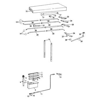
This section provides a detailed look at the essential elements that make up this piece of outdoor equipment. Understanding the various functional units helps ensure efficient maintenance, proper troubleshooting, and seamless operation over time.
Primary Mechanical Units
- Drive System: Powers the movement and ensures stability on uneven surfaces.
- Transmission Assembly: Regulates speed and provides smooth gear transitions for enhanced performance.
- Control Levers: Facilitate maneuvering and enable precise steering while operating.
Engine and Auxiliary Components
- Power Source: Generates the energy needed for both propulsion and task-specific functions.
- Fuel Supply System: Delivers a steady flow of fuel to maintain consistent engine performance.
- Cooling Mechanism: Prevents overheating and ensures optimal working temperatures during prolonged use.
Each component plays a crucial role in the seamless operation of the machine, ensuring reliability across various conditions. Proper upkeep of these elements guarantees long-lasting performance and efficiency.
Engine Structure and Key Features
The internal structure of the engine is designed to ensure efficient energy conversion and seamless operation under various conditions. This section explores the fundamental components and characteristics that enable smooth mechanical function and longevity, emphasizing precision engineering and reliability.
Piston and Cylinder Configuration: The alignment between pistons and cylinders plays a critical role in maintaining optimal power output. The balance achieved in this setup reduces vibrations, enhancing operational stability.
Cooling Mechanism: An integrated cooling system helps prevent overheating during extended usage, ensuring consistent performance. The circulation of coolant around key components keeps the temperature within ideal parameters.
Fuel Delivery System: The motor relies on an efficient fuel injection process, which maximizes combustion and reduces emissions. Accurate delivery timing improves both energy output and environmental compliance.
Lubrication Network: A well-organized lubrication system minimizes friction between moving parts, prolonging the engine’s service life. Proper lubrication reduces wear and ensures smoother operation across all workloads.
Transmission System Layout Explained
The transmission system ensures the efficient transfer of power from the engine to the wheels, enabling smooth movement and precise control across different terrains. This mechanism is crucial for optimizing performance, reducing energy loss, and maintaining stability during operation.
Power flow begins at the engine and passes through a series of gears, which manage speed and torque to suit specific tasks. The system’s design incorporates gear selectors, allowing the operator to switch between speeds or modes as needed, enhancing flexibility in various working conditions.
Key components, such as drive belts or chains, further distribute force to essential elements, ensuring all parts operate harmoniously. Additionally, modern systems often include clutches or torque converters, which help regulate transitions between gears, improving efficiency and minimizing wear.
Proper maintenance of the transmission system ensures reliable operation and extends the lifespan of the equipment. Regular inspection of gears, lubrication points, and belts is essential for preventing breakdowns and maximizing productivity over time.
Detailed View of the Auger Assembly
The auger mechanism plays a pivotal role in moving and processing material efficiently. Understanding how each component interacts within this system provides insight into its maintenance and performance, ensuring smooth operation during demanding tasks.
Main Components and Their Functionality
The auger consists of several interconnected elements designed to optimize movement. Spiraled blades rotate to gather material and propel it through the chute, ensuring consistent flow. The central shaft supports these blades, providing stability and allowing smooth rotation. Bearings and bushings minimize friction, preventing wear and extending the machine’s lifespan.
Inspection and Maintenance Tips
Regular checks of the auger are essential to prevent breakdowns. Pay attention to bolts and fasteners securing the blades, ensuring they remain tight during operation. Look for signs of wear on the bearings, and apply grease as needed to reduce friction. Replacing damaged components promptly helps maintain optimal performance and prevents further mechanical issues.
Control Panel and Handlebar Elements
The control panel and handlebar components are essential for the operation and maneuverability of the machinery. These elements provide the user with the necessary interfaces to manage various functions while ensuring comfort and safety during use. Understanding their layout and functionality is crucial for effective performance and maintenance.
Control Panel Overview
The control panel serves as the command center, featuring an array of buttons, switches, and gauges that monitor and control the machine’s performance. Each component is designed for intuitive access, allowing operators to make quick adjustments and keep track of vital information, such as speed and operational status. Proper knowledge of these features enhances the overall user experience.
Handlebar Functionality
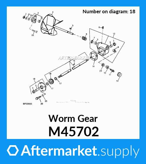
The handlebar is not only a crucial steering mechanism but also incorporates additional controls for convenience. Features such as throttle levers and safety switches are typically integrated, ensuring that the operator can maintain control while adjusting settings. Ergonomic design elements are also considered to reduce fatigue during prolonged use, promoting efficiency and comfort.
Chute Rotation and Deflection Mechanism
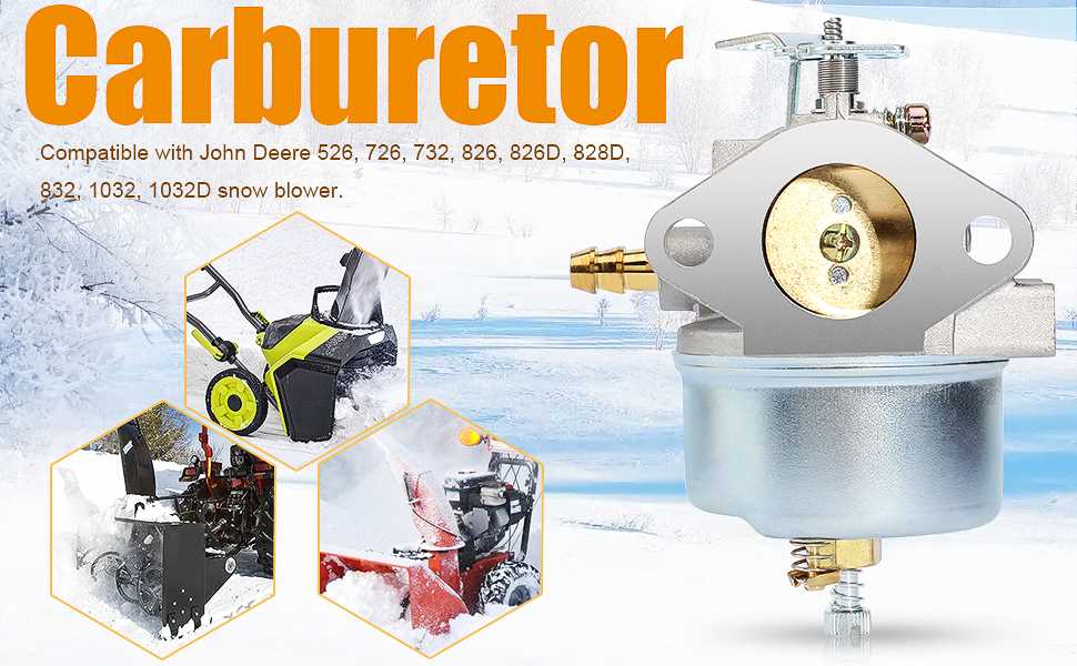
The mechanism responsible for the rotation and deflection of the chute plays a crucial role in directing material flow effectively. This system ensures that debris or grass clippings are expelled in the desired direction, enhancing operational efficiency and user control.
Components and Functionality
Key components of this mechanism include gears, pivot points, and actuators, which work in unison to allow for smooth adjustments. The interaction between these parts facilitates precise movement, enabling users to adapt the discharge angle based on specific needs.
Maintenance and Adjustments
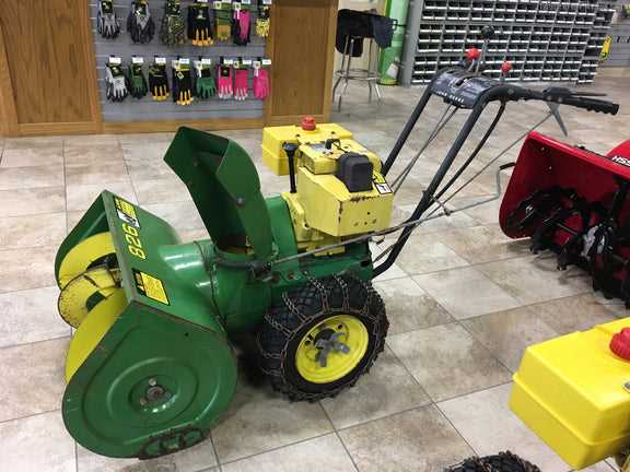
Regular inspection and maintenance of the chute rotation system are essential for optimal performance. Lubrication of moving parts and timely adjustments can significantly enhance the lifespan of the mechanism, ensuring it continues to function at its ultimate capacity.
Fuel System Components Breakdown
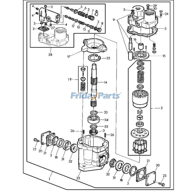
The fuel system is a vital part of any engine, ensuring the proper delivery and management of fuel for optimal performance. Understanding its components helps in diagnosing issues and maintaining efficiency. This section explores the key elements involved in the fuel delivery process.
Main Components
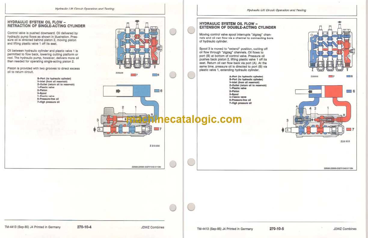
- Fuel Tank: Stores the fuel until it is needed by the engine.
- Fuel Pump: Moves fuel from the tank to the engine, creating the necessary pressure.
- Fuel Filter: Cleans the fuel by removing impurities before it reaches the engine.
- Fuel Lines: Transport fuel from the tank to the engine and return excess fuel.
- Injectors: Atomize the fuel and deliver it into the combustion chamber.
Supporting Elements
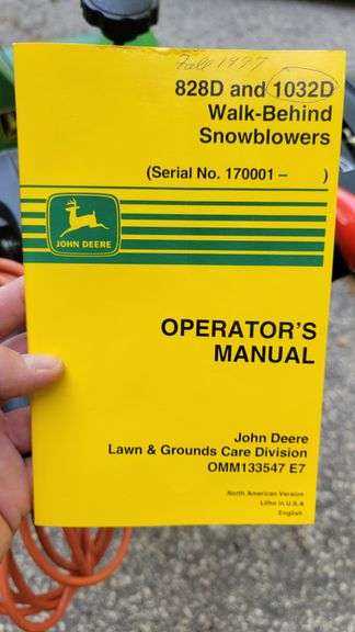
- Fuel Pressure Regulator: Maintains consistent fuel pressure within the system.
- Throttle Body: Controls the amount of air-fuel mixture entering the engine.
- Return Lines: Ensure that excess fuel is redirected back to the tank.
By familiarizing yourself with these components, you can enhance your understanding of the fuel system’s functionality and maintain the equipment more effectively.
Belt and Pulley Configurations
Understanding the arrangement and function of belts and pulleys is crucial for ensuring optimal performance and longevity of machinery. These components work together to transmit power efficiently, influencing the overall operation of the system. Analyzing the layout can provide insights into maintenance needs and potential upgrades.
Importance of Proper Alignment
Proper alignment of belts and pulleys is essential for minimizing wear and tear. Misalignment can lead to increased friction, reduced efficiency, and premature failure of components. Regular checks and adjustments can help maintain the desired performance levels.
Common Configurations
Several typical arrangements are found in various systems, each serving specific purposes. Below is a summary of some common configurations:
| Configuration Type | Description | Advantages |
|---|---|---|
| Open Belt Drive | Two pulleys connected by a single belt. | Simpler design, easy to replace. |
| Cross Belt Drive | Belt crosses over between pulleys. | Reduces slip, increases grip. |
| Compound Drive | Multiple belts connecting various pulleys. | Distributes load, increases power transfer. |
By recognizing the types and functions of these configurations, users can better manage their machinery’s operational efficiency and address potential issues proactively.
Tire Specifications and Axle Design
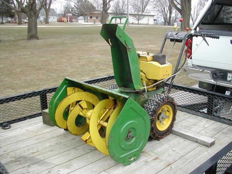
The performance and stability of agricultural machinery heavily depend on the quality of tires and the design of axles. These components are crucial for ensuring efficient operation across various terrains, influencing everything from traction to load distribution.
When selecting tires, several specifications need to be considered:
- Size: The dimensions, including width and aspect ratio, impact maneuverability and ground contact.
- Tread Pattern: Different designs offer varying levels of grip and soil preservation.
- Load Capacity: Each tire must support the weight of the equipment while ensuring safety and stability.
- Inflation Pressure: Proper pressure is essential for optimal performance and longevity.
Axle design also plays a significant role in machinery functionality:
- Material Strength: High-quality materials enhance durability and resistance to wear.
- Axle Configuration: The arrangement affects load distribution and stability during operation.
- Length and Width: These dimensions can influence turning radius and overall handling.
- Suspension Compatibility: Integration with the suspension system is critical for smooth operation.
Understanding these aspects helps ensure that the machinery operates effectively, maximizing productivity and minimizing downtime.
Replacement Guidelines for Wear Parts
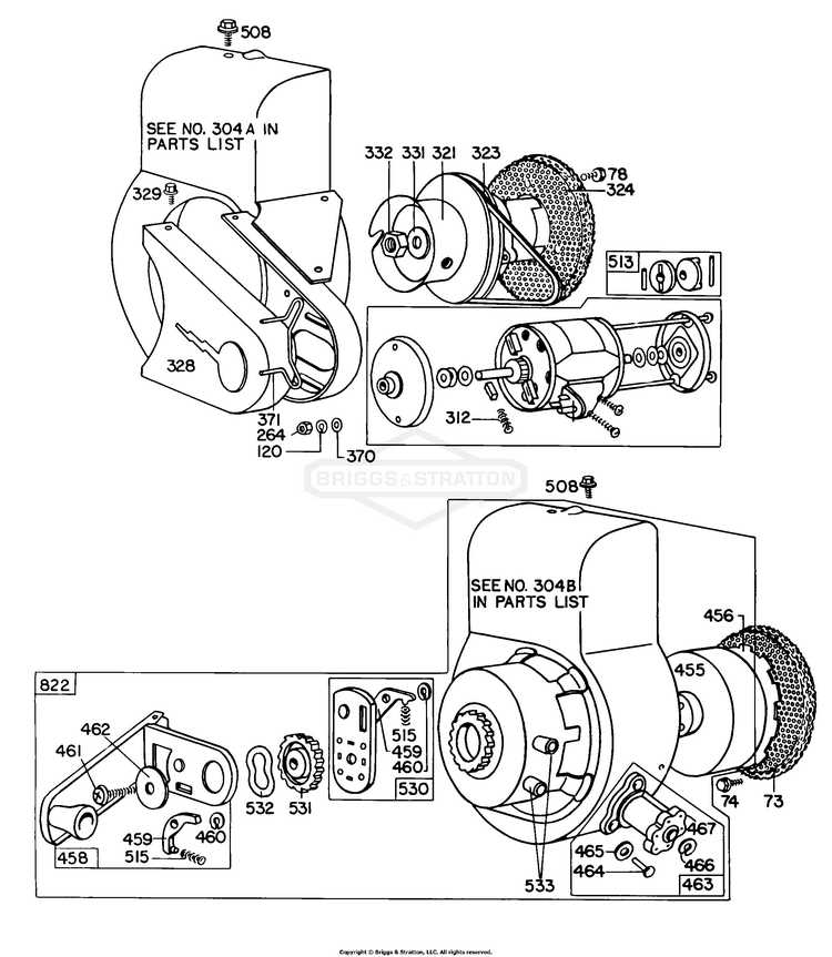
Maintaining optimal performance of machinery requires regular attention to components that experience significant wear over time. These elements are crucial for efficient operation and should be replaced as needed to prevent further damage and ensure longevity. Understanding when and how to replace these components can lead to better functionality and reduced downtime.
Assessment of Condition: Regular inspection is essential. Look for signs of wear such as cracks, deformation, or excessive corrosion. Conducting routine checks will help identify which components need immediate replacement and which can wait.
Timing for Replacement: Replace worn elements promptly to avoid impacting other connected systems. If a part shows signs of failure, it’s advisable to replace it during scheduled maintenance to minimize unexpected breakdowns.
Quality of Replacement: Always opt for high-quality replacements that meet or exceed original specifications. Using inferior components can lead to further issues and compromise the overall efficiency of the machine.
Proper Installation: Follow manufacturer guidelines for installation. Ensure all fittings are secure and that any adjustments required for the new component are made accurately. Incorrect installation can lead to premature failure.
Record Keeping: Maintain detailed records of replacements and maintenance activities. This information is invaluable for understanding usage patterns and planning future maintenance schedules effectively.
Maintenance Tips for Long-Term Performance
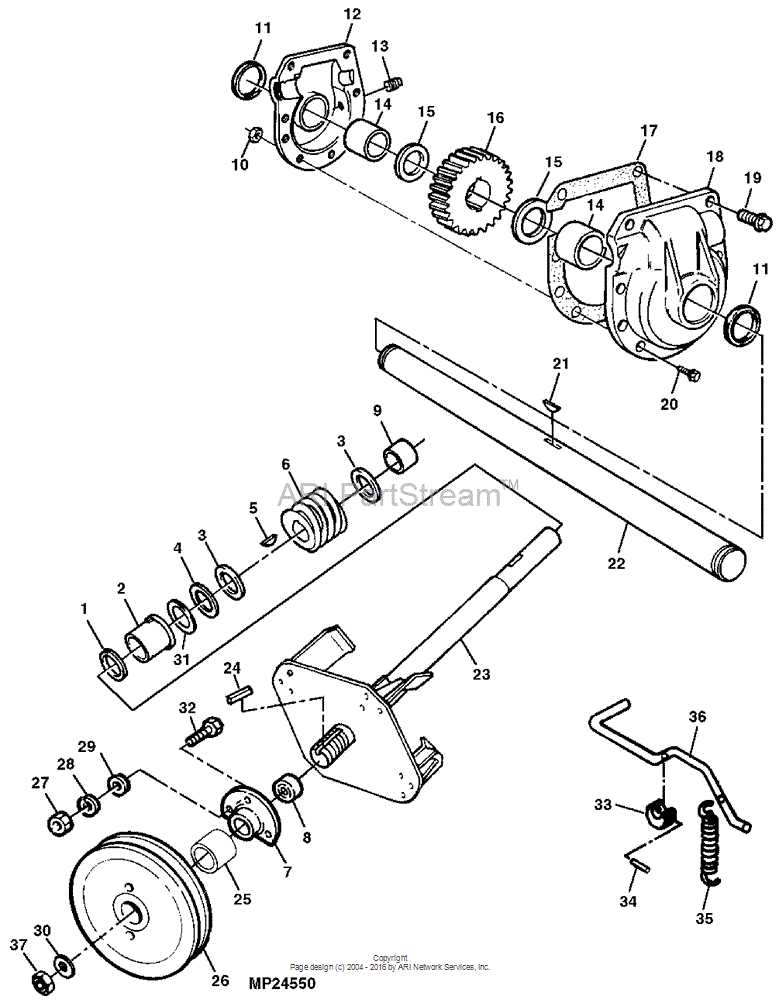
Regular upkeep is essential for ensuring the longevity and efficiency of your equipment. By implementing a structured maintenance routine, you can avoid costly repairs and enhance overall functionality. Understanding key practices will help you preserve performance over time.
1. Routine Inspections: Conduct frequent evaluations of your machinery to identify any wear or damage. Early detection can prevent more significant issues down the line.
2. Lubrication: Ensure all moving components are adequately lubricated to minimize friction. This practice not only extends the life of parts but also enhances operational efficiency.
3. Cleanliness: Keep your equipment clean from debris and dirt. Regular cleaning helps maintain optimal performance and prevents corrosion.
4. Fluid Checks: Regularly monitor and replace fluids as necessary. Proper fluid levels are crucial for preventing overheating and ensuring smooth operation.
5. Follow Manufacturer Guidelines: Always adhere to the recommended maintenance schedule provided by the manufacturer. This ensures your equipment operates within the designed specifications.
By following these essential tips, you can significantly improve the durability and reliability of your machinery, ensuring it remains in peak condition for years to come.
Troubleshooting Common Operational Issues
Addressing frequent operational challenges is crucial for maintaining efficiency and extending the lifespan of your machinery. Understanding these common issues can help operators quickly identify and resolve problems, minimizing downtime and enhancing productivity.
Identifying Performance Problems
One of the initial steps in troubleshooting is recognizing symptoms of performance issues. If the equipment exhibits irregular sounds or decreased power, it may indicate underlying mechanical problems. Regular inspections and preventive maintenance are essential in preventing these complications from escalating.
Resolving Electrical Failures
Electrical failures can severely impact functionality. If the machinery fails to start or responds inconsistently, check the battery and connections for corrosion or loose wiring. Ensuring that all electrical components are functioning properly will help achieve optimal performance.