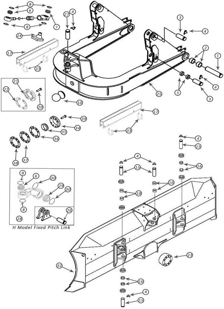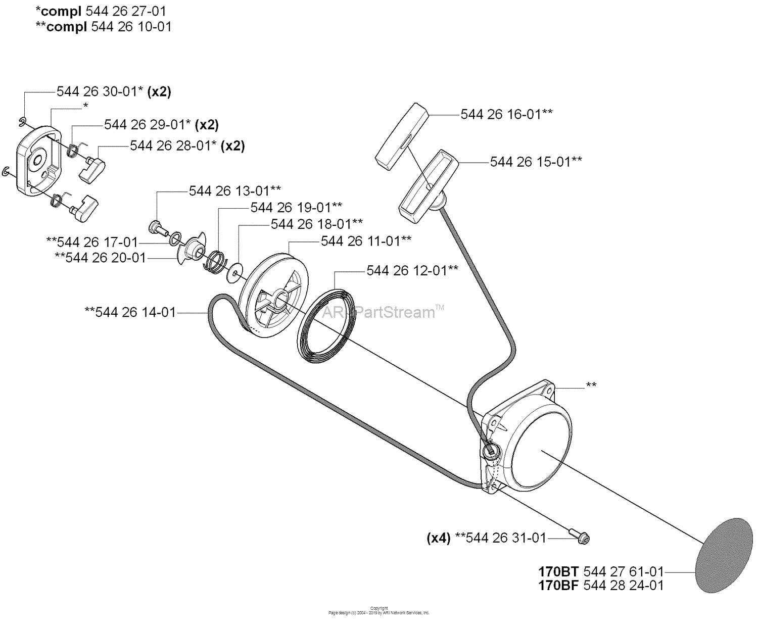
john deere 170 parts diagram

When maintaining or repairing agricultural machinery, understanding its internal structure is crucial for efficient operation. Knowing the arrangement and connections of various elements ensures smoother functioning, easier troubleshooting, and longer lifespan. This section provides a detailed look into how specific pieces come together to form a reliable, high-performance machine.

Exploring the assembly of these elements reveals how each piece is designed to work in harmony with others, ensuring seamless operation. Whether it’s regular upkeep or necessary repairs, having a clear overview of the setup makes it easier to address issues and maintain optimal performance. This guide is intended to help users visualize the connections and understand how everything fits together, improving overall efficiency.

For those looking to enhance their knowledge or perform hands-on work, this breakdown will serve as a useful tool. By delving deeper into the structure, users can more confidently approach any maintenance or repair tasks with the insight provided here.

Overview of John Deere 170 Components

The machine in question consists of several interconnected elements that work together to ensure efficient performance and smooth operation. Understanding the key structures and how they function will help users maintain and repair the equipment when necessary. Each element is engineered for durability and to fit seamlessly within the overall system.

Engine Parts Breakdown

Understanding the internal components of an engine is essential for maintaining its performance and longevity. This section provides an in-depth look at the key elements that make up the motor, ensuring smooth and efficient operation. By identifying and examining these critical elements, one can ensure proper maintenance and timely replacements when needed.

Component Description
Engine A powerful mechanism designed to drive the machine’s operation, providing the necessary force to handle various tasks.
Transmission This system is responsible for transferring power from the engine to the wheels, ensuring controlled movement and speed.
Chassis The robust frame that supports the overall structure, giving it stability and strength during usage.
Steering System A set of components allowing precise directional control, providing ease of maneuverability.
Component Description
Cylinder Block The foundation of the motor, housing the cylinders and other vital mechanisms for power generation.
Pistons Movable components within the cylinders, responsible for converting fuel combustion into mechanical movement.
Crankshaft A rotating mechanism that transforms the linear motion of the pistons into rotational force, driving the engine.
Camshaft Controls the opening and closing of valves, regulating the intake of air

Transmission System Overview

The transmission system plays a crucial role in ensuring efficient power delivery from the engine to the wheels, enabling smooth movement and control. It is responsible for managing gear changes and optimizing the performance of the vehicle, adapting to various terrains and workloads. Understanding the components involved in this process can help in maintaining and troubleshooting the system effectively.

Key Functions: The transmission’s primary function is to modulate speed and torque, allowing the vehicle to operate efficiently under different conditions. It also works to prevent engine overload by adjusting the power output according to the load and driving situation.

Components Overview: Various gears, linkages, and mechanisms are involved in the process, all working together to ensure precise operation. Regular maintenance of these parts can significantly extend the system’s lifespan and improve overall performance.

Electrical Components and Wiring

The electrical system plays a crucial role in ensuring the proper functionality of various equipment, managing power distribution and connecting key features. A well-maintained wiring setup ensures smooth operation and prevents potential issues related to performance or safety.

Main Electrical Connections

Several essential elements are involved in the electrical configuration, ranging from wiring to specific connectors. Ensuring that all cables are properly routed and securely attached helps in avoiding malfunctions and prolongs the system’s lifespan.

  • Primary wiring harness
  • Battery terminals and connections
  • Fuses and relays for protection

Wiring Maintenance Tips

Maintaining the electrical components requires regular inspection and preventive care. Common areas to check include the condition of the cables, tightness of connections, and the integrity of the insulation.

  1. Check all wiring for signs of wear or corrosion.
  2. Ensure that connectors are secure and free of debris.
  3. Replace damaged fuses and verify proper voltage distribution.

Steering Mechanism Layout

The steering system plays a critical role in ensuring the smooth and precise maneuvering of any vehicle. Understanding the structure of this system is essential for proper maintenance and efficient operation. Below is an overview of how various components work together to control the vehicle’s direction, ensuring responsive handling and stability during movement.

Main Components Overview

  • Steering Wheel: The control interface that the operator uses to steer. It transmits input to the mechanical or hydraulic systems that actually turn the wheels.
  • Steering Column: A shaft connecting the wheel to the steering mechanism. It transfers the rotational motion from the driver’s hands to the system.
  • Linkages: These components transfer the movement from the column to the wheels. They ensure that the rotational force is evenly distributed to both sides.

How Steering Functions

  1. Input Transmission: When the driver rotates the wheel, the steering column engages and transmits this movement to the linkage system.
  2. Direction Control: The linkages then act on the front wheels, directing them left or right, depending on the input provided.
  3. Stability: A properly maintained system ensures that the vehicle

    Fuel System Diagram

    The fuel system plays a crucial role in the overall performance and efficiency of a machine. This section provides a comprehensive overview of the components and layout involved in the fuel delivery mechanism, ensuring optimal operation and longevity of the equipment.

    Key Components

    • Fuel Tank: Stores the fuel required for operation.
    • Fuel Pump: Transports fuel from the tank to the engine.
    • Fuel Filter: Removes impurities from the fuel before it reaches the engine.
    • Fuel Lines: Pathways that carry fuel to various components.
    • Injectors: Deliver fuel directly into the combustion chamber for ignition.

    System Layout

    The arrangement of these elements ensures efficient fuel flow and effective combustion. A well-designed fuel delivery system enhances engine performance, reduces emissions, and improves fuel economy. Understanding the layout helps in troubleshooting and maintenance, ensuring that each component functions as intended.

    Chassis and Frame Structure

    The chassis serves as the foundational element of machinery, providing essential support and stability during operation. This framework is designed to endure various loads and stresses, ensuring the efficient performance of the entire system. A well-constructed frame not only enhances durability but also facilitates the seamless integration of other components, optimizing functionality and reliability.

    Design and Materials

    The choice of materials and the design principles applied in the construction of the frame are crucial for achieving strength and longevity. Typically, robust metals such as steel or high-grade alloys are utilized to withstand the rigors of demanding tasks. The design may include reinforcements and strategically placed joints to enhance resilience while minimizing overall weight.

    Components and Features

    Various elements contribute to the overall structure of the chassis, ensuring that it meets operational demands. Key components include support brackets, cross members, and mounting points for essential systems. These features are meticulously arranged to balance the load distribution and maintain structural integrity.

    Component Function
    Support Brackets Provide stability and reinforcement to the frame.
    Cross Members Enhance rigidity and load distribution across the structure.
    Mounting Points Facilitate the attachment of various systems and components.

    Hydraulic System Layout

    The hydraulic system is a crucial component in many agricultural machines, enabling effective movement and control of various implements. This layout illustrates the essential elements that contribute to the overall functionality, providing insights into how fluid dynamics are harnessed for optimal performance.

    At the heart of this arrangement are the hydraulic pumps, responsible for generating the necessary pressure to move fluids through the system. These pumps work in conjunction with valves that regulate the flow, ensuring precise control over the machinery’s operations. Additionally, hoses and connectors facilitate the transfer of hydraulic fluid, maintaining the integrity of the system under varying conditions.

    Understanding this configuration aids in diagnosing issues and performing maintenance, as recognizing each component’s role enhances the ability to troubleshoot effectively. Proper maintenance of the hydraulic layout not only extends the lifespan of the equipment but also maximizes its operational efficiency.

    Brake Components and Assembly

    The braking system is a crucial part of any machinery, ensuring safety and control during operation. Understanding the individual elements and their arrangement is essential for maintaining optimal functionality. This section provides an overview of the various components involved in the braking mechanism and their assembly process.

    Main Components

    • Brake Pedal: The interface through which the operator engages the braking system.
    • Brake Cylinder: Converts the force applied to the pedal into hydraulic pressure.
    • Brake Shoes: Friction materials that press against the drum to create stopping power.
    • Brake Drum: The cylindrical part that the shoes press against to slow down the vehicle.
    • Spring Mechanism: Ensures that the brake shoes return to their resting position when not engaged.

    Assembly Process

    1. Begin by securing the brake cylinder to the designated mounting location.
    2. Attach the brake pedal and ensure it operates smoothly.
    3. Install the brake shoes inside the drum, ensuring proper alignment.
    4. Connect the spring mechanism to facilitate the return of the brake shoes.
    5. Conduct a thorough inspection to ensure all components are securely attached and functioning as intended.

    Wheel and Axle Configuration

    john deere 170 parts diagram

    The arrangement of wheels and axles is crucial for the overall functionality and performance of machinery. This configuration directly impacts stability, maneuverability, and load distribution, making it a fundamental aspect of design. A well-thought-out layout ensures efficient operation while minimizing wear and tear on components.

    Understanding the mechanics behind wheel and axle systems is essential for optimizing equipment performance. Each element plays a significant role in ensuring that power is effectively transmitted from the engine to the ground, allowing for smooth movement and control.

    The geometry of the wheel and axle setup can influence various performance metrics. For instance, the distance between the axles, the diameter of the wheels, and the materials used can all contribute to how the equipment handles different terrains. Properly calibrated configurations lead to enhanced traction and reduced slippage, resulting in a more productive operation.

    Regular maintenance and inspection of the wheel and axle assembly are vital for longevity. By identifying potential issues early, operators can prevent significant breakdowns and ensure that their machinery remains reliable and efficient over time.

    Cooling System Parts Layout

    The layout of the cooling mechanism is essential for maintaining optimal performance and preventing overheating in agricultural machinery. Understanding the various components and their arrangement aids in effective maintenance and troubleshooting.

    This section will outline the key elements involved in the cooling system, ensuring that each part is functioning harmoniously to achieve efficient temperature regulation.

    • Radiator: Responsible for dissipating heat from the coolant.
    • Water Pump: Circulates the coolant throughout the system.
    • Thermostat: Regulates coolant flow based on temperature.
    • Hoses: Facilitate the movement of coolant between components.
    • Fan: Assists in airflow over the radiator to enhance cooling.
    • Coolant Reservoir: Stores excess coolant for optimal system pressure.

    Each component plays a vital role in ensuring the cooling system operates efficiently, contributing to the overall longevity and reliability of the machinery.