When it comes to maintaining and repairing heavy machinery, having a clear understanding of the various mechanical elements is essential. Whether you’re dealing with maintenance, troubleshooting, or replacement, the ability to locate and recognize specific elements of equipment can make the process smoother and more efficient. This guide aims to provide clarity on how these mechanical components fit together in one unified system.
The breakdown of different mechanisms in this type of machinery can sometimes be intricate. However, with the right visual representation, even the most complex systems can be simplified. Identifying and referencing individual elements accurately is crucial for anyone looking to ensure optimal functionality and longevity of the equipment.
This resource is designed to help you navigate the structure of the equipment, ensuring that every element is easily recognizable. By following the instructions and illustrations, you can streamline your approach to maintenance tasks, improving efficiency and reducing downtime.
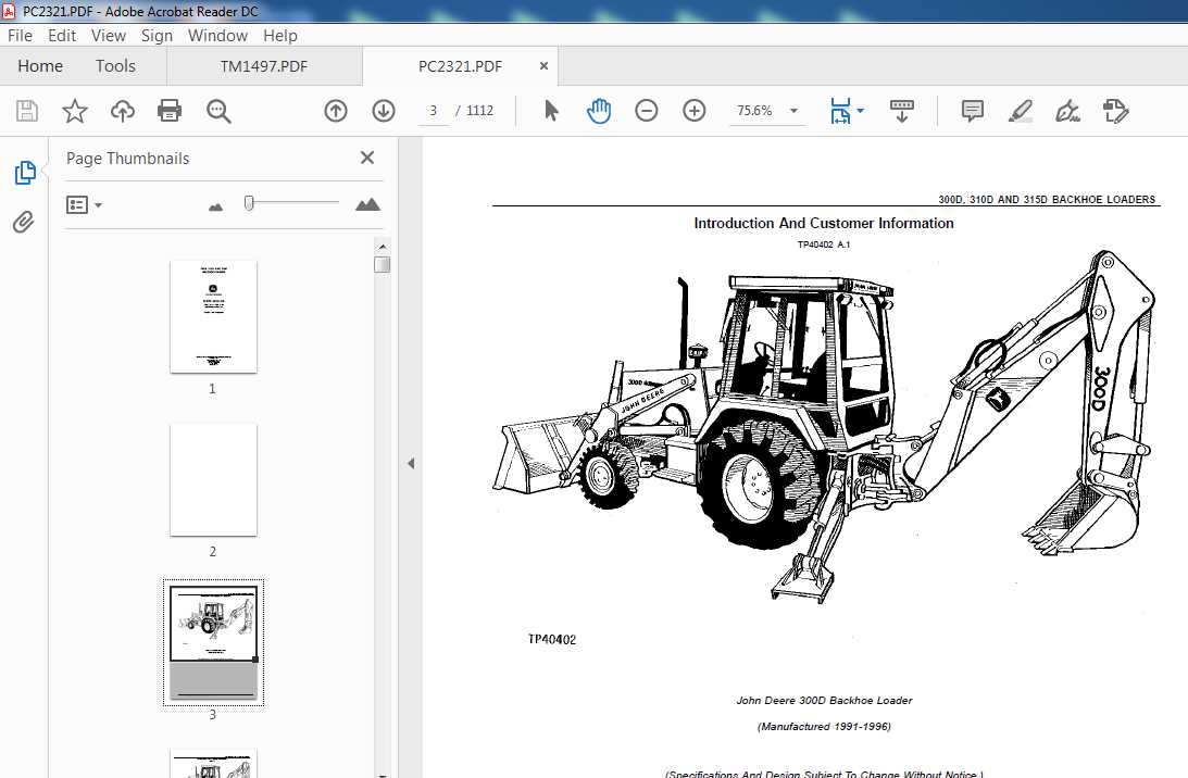
Overview of John Deere 300 Loader Components
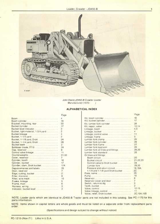
The equipment in question is known for its sturdy construction and reliable operation across various tasks. This section provides a general understanding of the key mechanisms that enable the system to function efficiently in different applications. By breaking down its individual elements, one can better appreciate how each part contributes to the overall performance.
Hydraulic System
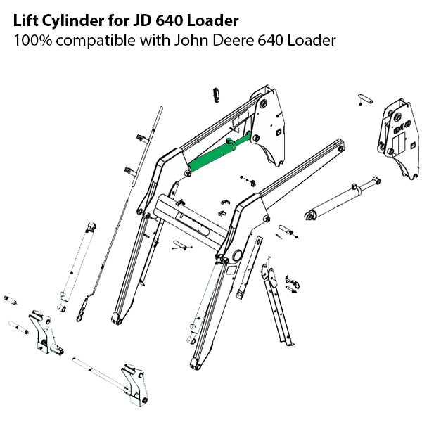
A critical aspect of this machine is its hydraulic setup, which powers the lifting and movement of the front assembly. This system consists of pumps, hoses, and valves that work together to ensure smooth operation and precise control. Proper maintenance of the hydraulic components is essential to prevent wear and tear over time.
Frame and Attachments
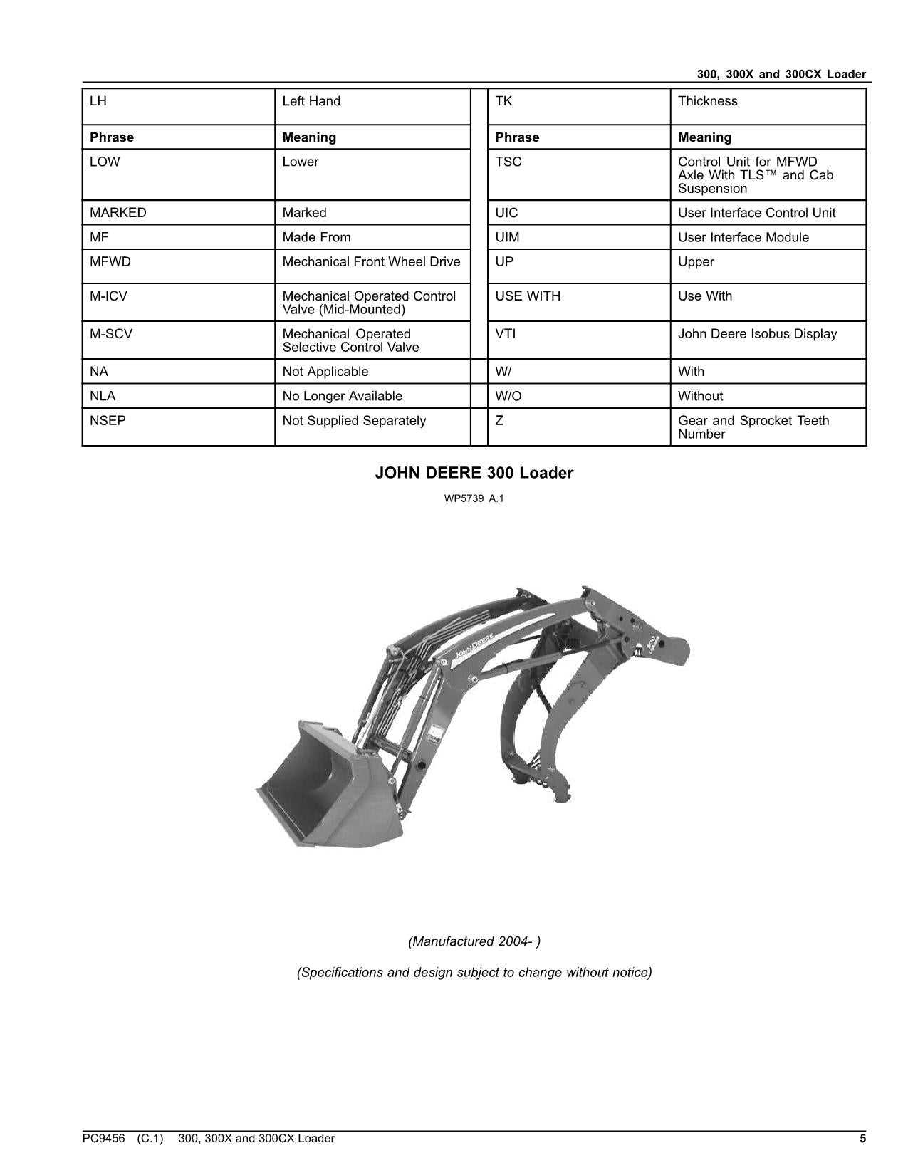
The sturdy frame forms the backbone of the machine, providing support for the various attachments. These tools, designed for tasks such as digging, lifting, or transporting, can be swapped out depending on the specific job. The design of the frame ensures compatibility with a range of attachments, making the system versatile for different types of work.
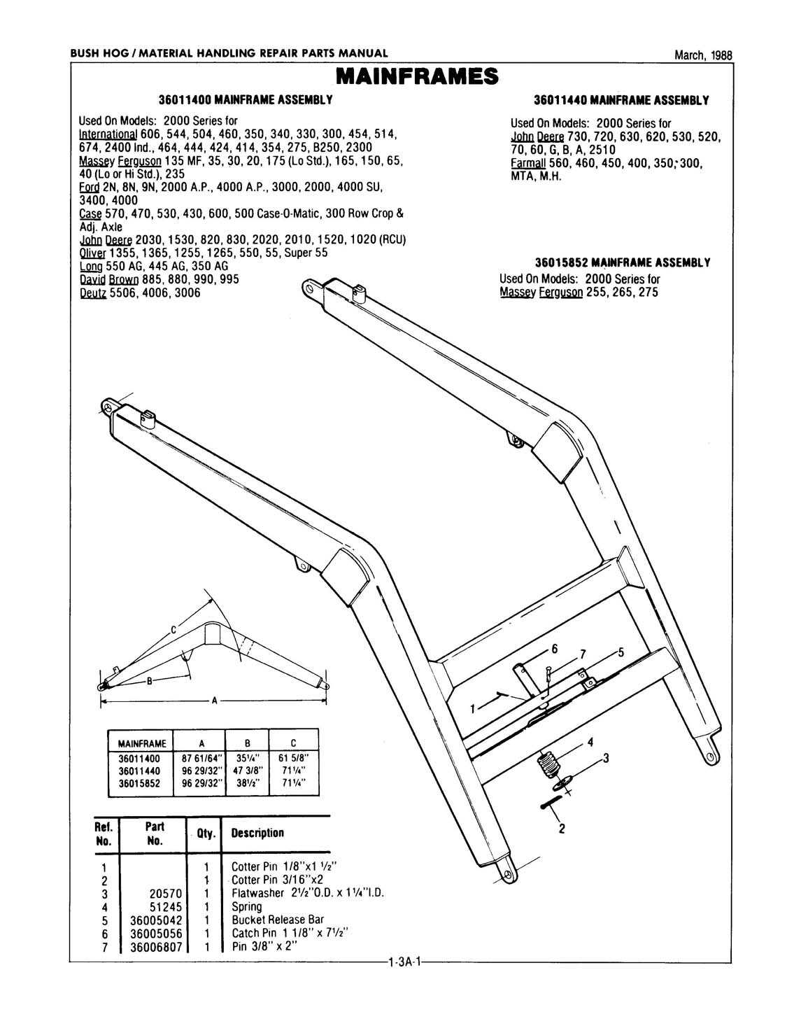
Main Frame and Structural Parts
The central framework and key structural components play a vital role in ensuring the strength and durability of the machinery. This section focuses on the primary elements that provide stability and support to the overall construction. These components are crucial for maintaining balance, absorbing operational stresses, and contributing to the machine’s overall lifespan.
- Chassis: The base structure that supports other essential components and withstands heavy loads during operation.
- Support beams: Reinforcement elements that ensure rigidity and reduce the risk of deformation under pressure.
- Pivotal joints: Key connection points allowing controlled movement between sections while maintaining structural integrity.
- Mounting brackets: Attachment points for additional equipment or accessories, designed to distribute weight evenly across the frame.
- Crossmembers: Horizontal elements that enhance stability and contribute to a well-balanced frame structure.
All these parts work together to form the backbone of the equipment, providing the necessary support for various attachments and ensuring reliable performance during demanding tasks.
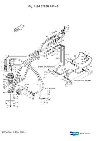
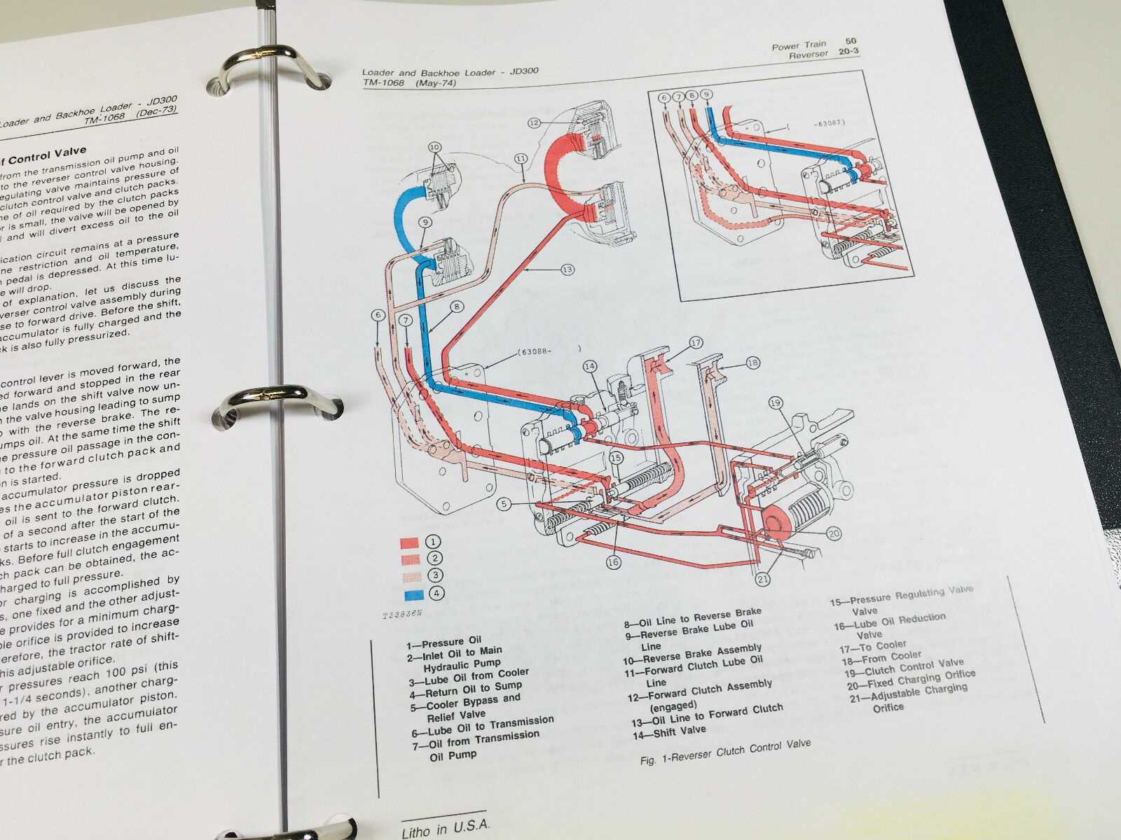
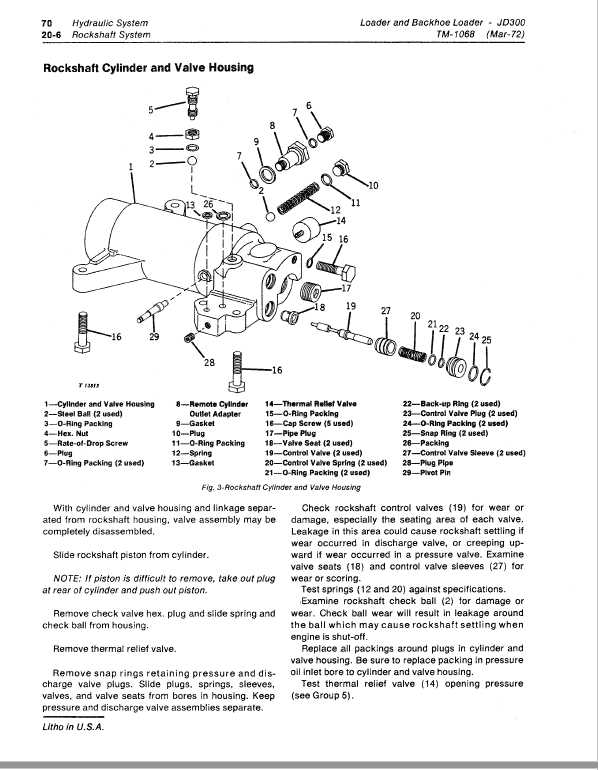
Hydraulic System Layout for the 300 Loader
The hydraulic configuration of this lifting device is designed to ensure smooth operation and efficient handling of heavy loads. It relies on interconnected components that work together to provide controlled fluid pressure, ensuring the proper functioning of lifting and steering mechanisms. Understanding the key elements of this system is crucial for maintenance and troubleshooting.
Pump: The hydraulic pump is responsible for generating the fluid pressure needed to power various functions. It draws fluid from the reservoir and directs it to the control valves, ensuring sufficient force for movement.
Control Valves: These valves regulate the direction and flow of hydraulic fluid. By adjusting the valves, the operator can control the lifting, tilting, and other motions of the equipment, ensuring precision in operation.
Cylinders: The hydraulic cylinders convert fluid pressure into mechanical force. They are the main actuators that enable the movement of arms and other movable parts. Their performance is critical to the overall functionality of the system.
Hydraulic Lines: The network of hoses and pipes transports the fluid between the different components. Ensuring the integrity of these lines is essential for preventing leaks and maintaining consistent
Bucket Attachment Parts Breakdown
The bucket attachment is a crucial component for handling a variety of tasks, offering versatility and efficiency. This breakdown provides a detailed overview of the main elements that ensure optimal performance. Each part plays a specific role in maintaining the integrity and functionality of the equipment, contributing to seamless operation during heavy-duty applications.
Key sections of the bucket assembly include the connecting brackets, which secure the attachment to the arm, and the cutting edge, designed to handle rigorous material handling. Additionally, side panels reinforce the structure, providing extra durability, while the hinge mechanism ensures smooth articulation during use. By understanding these components, users can ensure better maintenance and efficiency in everyday operations.
Lift Arms and Linkage Diagram
The lift arms and linkage are critical components responsible for managing the vertical movement and ensuring stability during operation. This system allows for smooth and controlled raising and lowering of the equipment, maintaining proper balance and load distribution. Understanding the structure and functioning of these parts is key for effective maintenance and performance.
Main Elements of the Lift System
The lift arms are connected through a set of pivots and linkages, enabling synchronized motion. This arrangement allows the equipment to handle weight while minimizing strain on individual components. Regular checks of the linkage assembly can help prevent wear and ensure smooth operation.
Key Connections and Functionality
The linkage system includes several joints and pins that connect the arms to the frame. These connections are designed to withstand heavy loads and provide necessary flexibility during operation. Ensuring proper lubrication and alignment of these points is essential to avoid friction and component degradation.
| Component | Function | Maintenance Tip | |||||||||||||||||||||||
|---|---|---|---|---|---|---|---|---|---|---|---|---|---|---|---|---|---|---|---|---|---|---|---|---|---|
| Lift Arms | Provide vertical
Hydraulic Cylinder Placement and Function
Hydraulic cylinders are critical components in machinery, responsible for converting hydraulic energy into linear motion. Their strategic positioning directly influences the efficiency and effectiveness of the entire system, allowing for precise control and powerful force application. Proper placement of these cylinders is essential to ensure optimal performance. Factors such as load distribution, accessibility for maintenance, and the overall design of the equipment must be considered. Each cylinder’s location affects the machine’s stability and functionality, emphasizing the importance of a well-thought-out arrangement.
Understanding the role and placement of hydraulic cylinders is vital for optimizing machinery operations. Each type serves a unique purpose, contributing to the overall functionality and efficiency of the equipment. Steering and Control Mechanisms
The steering and control systems play a pivotal role in the operation of heavy machinery, ensuring precise navigation and handling. These mechanisms are designed to offer operators a seamless experience, allowing for efficient maneuverability in various environments. Understanding their components and functionality is essential for optimal performance and maintenance.
Regular inspection and maintenance of these systems are crucial to ensure longevity and reliability. Understanding each component’s function can significantly enhance operational efficiency and safety. Mounting Brackets and Hardware Details
The significance of mounting components and associated fasteners cannot be overstated in any machinery setup. These elements play a critical role in ensuring stability and functionality, serving as the foundation upon which other parts are attached. A thorough understanding of their specifications and arrangements is essential for effective maintenance and repair. Mounting brackets are typically crafted from robust materials, designed to endure the rigors of operation. Their primary function is to provide a secure attachment point for various components, allowing them to withstand stress during use. Proper alignment and installation of these brackets are vital for optimal performance. In addition to brackets, the hardware utilized in these assemblies includes nuts, bolts, and washers, which are crucial for securing components in place. Selecting the right type and size of fasteners is essential to prevent issues such as loosening or misalignment. Regular inspection and replacement of worn-out hardware can enhance overall reliability and longevity. Understanding the configuration and interrelations of these mounting solutions is key to achieving seamless operation. Regular maintenance and attention to detail in the installation process can significantly impact the efficiency and safety of the machinery. Engine Connection and Power TransmissionThe efficiency of a machine heavily relies on the seamless integration between its engine and the power delivery systems. Understanding the mechanics of how power is transmitted from the engine to various operational components is crucial for optimizing performance and ensuring reliability. This section delves into the intricate connections that facilitate energy transfer and the mechanisms involved in power distribution. Energy Transfer MechanismsPower transfer systems consist of several key elements that work together to convert engine output into functional energy. The primary components include drive shafts, gears, and couplings, each playing a vital role in the distribution of power. By efficiently transferring energy through these mechanisms, the overall performance of the equipment is enhanced, allowing for improved operational capabilities. Maintenance Considerations
Regular maintenance of the connection systems is essential for ensuring longevity and optimal functionality. This includes monitoring wear and tear on critical components, lubricating moving parts, and promptly addressing any signs of failure. A proactive approach to upkeep will not only extend the lifespan of the machine but also contribute to its operational efficiency. Loader Frame Support and StabilizationEnsuring optimal support and stabilization of the equipment’s structure is crucial for effective performance. This aspect focuses on maintaining the integrity of the assembly during operation, thereby enhancing both safety and efficiency. Proper reinforcement systems contribute significantly to the overall durability of the machinery. Frame support plays a vital role in distributing weight and resisting external forces. This involves utilizing robust components that can withstand stress while providing a stable platform for various attachments. Effective designs incorporate strategic placement of supports to minimize flex and enhance stability. Moreover, stabilization mechanisms are essential for maintaining balance, especially in uneven terrain. These mechanisms can include adjustable supports that adapt to different operating conditions, ensuring the equipment remains level and secure. The integration of these features not only improves functionality but also extends the lifespan of the machine. Ultimately, a well-designed support and stabilization system enhances the operational capabilities of the equipment, making it more versatile and reliable in various applications. Wheel and Axle Assembly PartsThe wheel and axle assembly is a crucial component in various machinery, facilitating movement and stability. This section explores the essential elements involved in this assembly, highlighting their functions and importance for overall performance. Key Components
The assembly consists of several vital components, including wheels, axles, bearings, and fasteners. Each part plays a specific role in ensuring smooth operation, from supporting the vehicle’s weight to enabling seamless rotation during movement. Maintenance ConsiderationsRegular maintenance of the wheel and axle assembly is essential for optimal performance. Inspections should focus on wear and tear of components, ensuring that all parts are secure and functioning correctly to prevent potential breakdowns and ensure safety during operation. Hydraulic Pump and Reservoir LocationThe hydraulic system is a vital component of many heavy machinery, ensuring efficient operation and power transmission. Understanding where the hydraulic pump and reservoir are situated can significantly enhance maintenance and repair processes. This section will provide insight into the typical placement of these critical components, helping users navigate their machinery more effectively. General Positioning
In most models, the hydraulic pump is usually mounted near the engine, allowing for a direct connection to the power source. This proximity ensures optimal performance and minimizes energy loss. The reservoir, which holds hydraulic fluid, is often located adjacent to the pump for easy access and efficient fluid circulation. The placement of these elements is designed to maximize functionality while facilitating routine inspections. Access and Maintenance Considerations
Accessing the hydraulic pump and reservoir is crucial for regular maintenance. Typically, these components are positioned in a way that provides ample space for servicing. Keeping the area around the pump and reservoir clear of obstructions is essential to perform necessary checks and fluid replacements efficiently. Regularly monitoring fluid levels and inspecting for leaks can prevent major issues and prolong the life of the hydraulic system. Maintenance Tips for Loader Components
Proper upkeep of machinery elements is crucial for ensuring optimal performance and longevity. Regular attention to these components not only enhances efficiency but also reduces the likelihood of unexpected breakdowns, leading to smoother operations in the long run. Regular Inspections
Conducting frequent evaluations of the various elements can help identify wear and tear before they escalate into major issues. Look for signs of corrosion, loose fittings, and any unusual sounds during operation. Early detection is key to preventing costly repairs. Lubrication and CleaningConsistent lubrication of moving parts is essential to minimize friction and prevent premature failure. Use the appropriate lubricant as specified in the manufacturer’s recommendations. Additionally, keeping surfaces clean from debris and dirt ensures smooth functioning and extends the lifespan of the components. |
