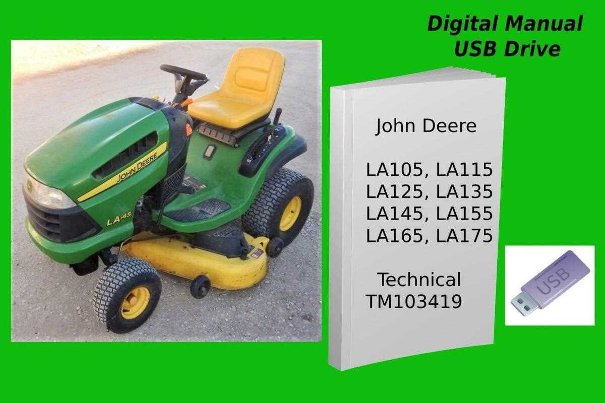
Electrical System: Detailed Parts Structure
The electrical system plays a crucial role in ensuring smooth operation and performance. It consists of several interconnected components that work together to provide power, control, and signal distribution. Understanding the layout and function of these elements is essential for proper maintenance and troubleshooting.
Key elements include the wiring harness, connectors, and switches that route electrical current throughout the equipment. Additionally, protective devices such as fuses and relays safeguard the system from overloads or short circuits. Each component has a specific purpose, and together they form an efficient network designed to handle various operational demands.
Regular inspection and replacement of worn-out elements are important to avoid potential malfunctions or downtime. The structure of the electrical system is designed for ease of access, allowing for quick repairs and adjustments when needed.
Fuel System Components for LA145
The fuel delivery mechanism is crucial for the optimal functioning of any lawn care machine. It comprises various elements that work in unison to ensure the engine receives the right amount of fuel for efficient operation. Understanding these components helps in maintaining and troubleshooting the system effectively.
The primary element is the fuel tank, which stores the liquid fuel until needed. Connected to the tank is the fuel line, a tube that transports the fuel to the engine. A fuel filter is also integrated into the system, designed to remove impurities from the fuel, protecting the engine from potential damage. Additionally, the fuel pump plays a vital role by transferring fuel from the tank to the carburetor or fuel injector, ensuring a steady flow for combustion.
Another important component is the carburetor, which mixes the fuel with air in the correct ratio for combustion. For those with modern systems, fuel injectors may replace the carburetor, delivering precise amounts of fuel directly into the combustion chamber. Lastly, the fuel shut-off valve is essential for controlling the flow of fuel, allowing for safe maintenance and storage.
Brake Assembly Parts and Function
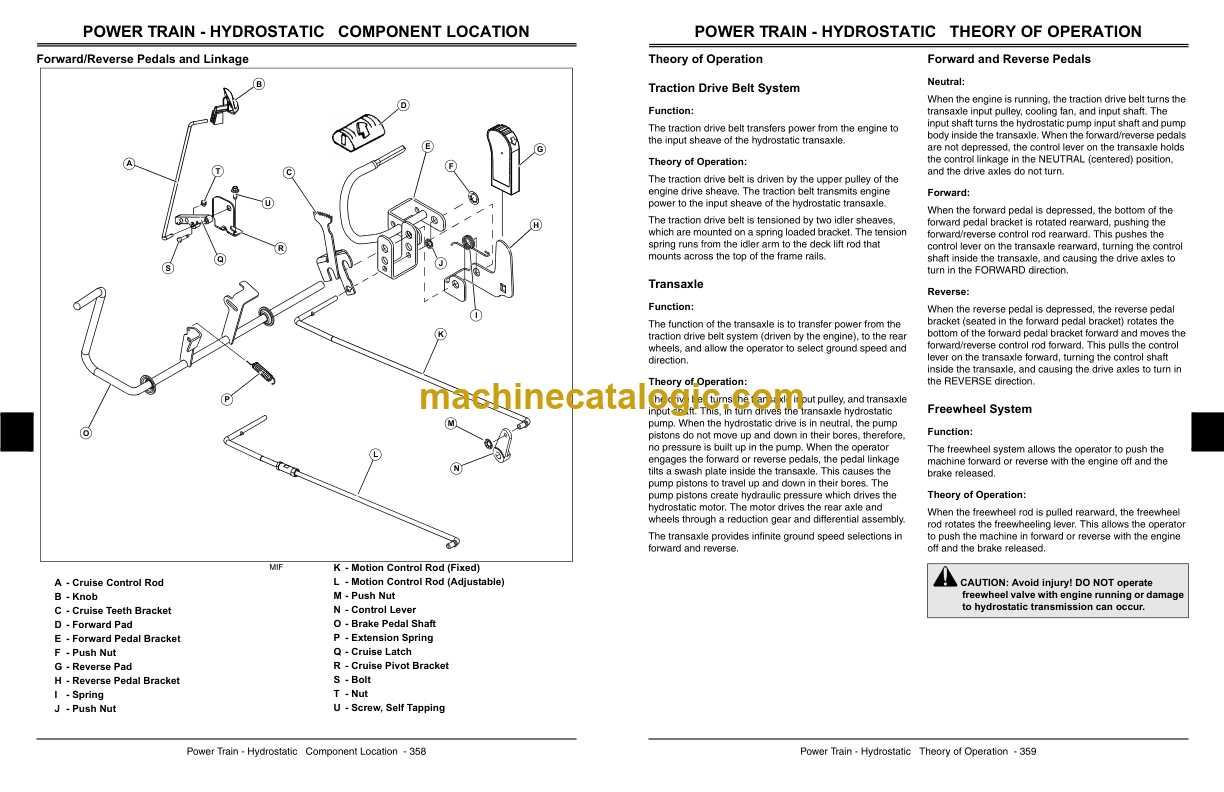
The brake system in a riding mower plays a crucial role in ensuring safety and control during operation. This mechanism consists of various components that work together to slow down or stop the machine effectively. Understanding the individual elements and their functions can aid in proper maintenance and troubleshooting.
Key Components: The primary elements of the brake system include the brake pedal, master cylinder, brake caliper, and brake pads. Each of these components serves a specific purpose in the overall functionality of the system.
The brake pedal is the operator’s interface, allowing the user to initiate braking by applying pressure. This action activates the master cylinder, which generates hydraulic pressure within the system. This pressure is crucial for the operation of the brake caliper, which clamps down on the brake pads to create friction against the rotor.
Functionality: When the brake pedal is pressed, hydraulic fluid is pushed from the master cylinder to the caliper, causing the brake pads to engage. This engagement results in the slowing of the machine, enabling smooth stops and enhanced control during operation. Regular inspection and maintenance of these components are essential to ensure optimal performance and safety.
Wheels and Tires: Parts and Sizes
This section focuses on the essential components associated with wheels and tires, highlighting their specifications and compatibility with various machines. Understanding these elements is crucial for ensuring optimal performance and longevity of the equipment.
Key components related to wheels and tires include:
- Tires: The primary contact point with the ground, available in various sizes and tread patterns to suit different terrains.
- Rims: The outer part of the wheel that holds the tire, varying in size and design to accommodate specific tire types.
- Bearings: Essential for smooth rotation, these components reduce friction between the wheel and axle.
- Hubcaps: Covers that protect the wheel’s inner components and enhance aesthetics.
When selecting tires and wheels, consider the following sizes:
- Diameter: The overall size of the tire, typically measured in inches.
- Width: The measurement across the tire’s tread, influencing traction and stability.
- Aspect Ratio: The ratio of the tire’s height to its width, affecting handling and comfort.
Properly matching these components ensures effective operation and extends the lifespan of the equipment.
Seat and Comfort Parts for LA145
Ensuring a pleasant experience during operation is essential for any vehicle. The comfort components play a significant role in enhancing user satisfaction and ease of use. This section explores the various elements designed to improve seating and overall comfort in the specified model.
- Seat Cushion: Provides essential support and padding for a comfortable ride.
- Backrest: Ergonomically designed to support the back and promote proper posture.
- Armrests: Offer additional support for arms, enhancing overall relaxation during operation.
- Seat Cover: Protects the cushion from wear and tear, while also providing a customizable look.
- Adjustable Mechanism: Allows for customization of seat height and position to accommodate different users.
- Seat Belt: Ensures safety during operation, keeping the user securely in place.
- Footrest: Provides a place for feet, improving stability and comfort during use.
Each of these components contributes to a more enjoyable and effective experience, making it crucial to select high-quality replacements when needed. Proper maintenance and timely replacements of these elements ensure longevity and enhanced comfort for operators.
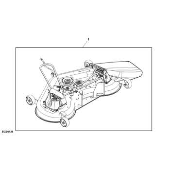
Mowing Deck Components Layout
The configuration of the mowing deck is crucial for achieving an efficient cutting performance. Each element within the assembly plays a significant role in ensuring a clean and even cut, contributing to the overall effectiveness of the machine. Understanding the layout of these components can aid in maintenance and troubleshooting.
- Deck Housing: The outer shell that encases the cutting mechanism, providing structural integrity and protection.
- Blades: Sharp, rotating elements responsible for trimming grass. Typically, these are arranged in a specific pattern for optimal cutting efficiency.
- Spindle Assembly: The part that connects the blades to the power source, allowing them to spin at high speeds.
- Anti-Scalp Wheels: Positioned along the edges of the deck, these wheels help maintain an even cutting height, preventing the blades from scalping the ground.
- Drive Belt: Transfers power from the engine to the spindle assembly, enabling blade rotation.
- Lift Mechanism: Allows the operator to raise or lower the deck for different cutting heights, ensuring versatility in various mowing conditions.
Familiarity with the arrangement and function of these components can enhance operational effectiveness and facilitate timely repairs, ultimately leading to a better mowing experience.
Hydraulic System Parts Overview
The hydraulic system plays a vital role in enhancing the functionality of various machinery, facilitating smooth operation and control of movements. Understanding the components that make up this system is essential for maintenance and repair, ensuring optimal performance and longevity of the equipment.
Key Components
- Pump: Responsible for generating hydraulic fluid flow, which is essential for the operation of the entire system.
- Reservoir: Stores hydraulic fluid and helps maintain the necessary level for consistent operation.
- Actuators: Convert hydraulic energy into mechanical movement, allowing various functions of the machinery.
- Valves: Control the direction and flow of hydraulic fluid, ensuring precise operation and responsiveness.
- Hoses and Fittings: Provide the necessary connections between components, facilitating the transfer of fluid throughout the system.
Maintenance Considerations
- Regularly check for leaks and signs of wear on hoses and fittings.
- Ensure that the reservoir is filled to the appropriate level with the correct hydraulic fluid.
- Inspect valves for proper function and responsiveness during operation.
- Monitor the performance of the pump and actuators to detect any irregularities early.
Blade and Cutting Mechanism Parts
The cutting system of a lawn maintenance machine is crucial for ensuring an effective and clean trim. This section outlines the various components involved in the cutting mechanism, emphasizing their functions and interconnections. Understanding these elements is essential for maintenance, repair, and optimization of cutting performance.
Key Components
The primary components of the cutting mechanism include the blade assembly, drive belt, and support structures. Each of these elements plays a vital role in the operation of the machine.
| Component |
Description |
| Blade Assembly |
Responsible for the actual cutting action, this component can vary in design and material based on the intended use. |
| Drive Belt |
This part transmits power from the engine to the blade assembly, enabling rotation and cutting action. |
| Spindle |
The spindle serves as the pivot point for the blade, allowing for smooth rotation during operation. |
| Deck |
This structure houses the cutting components and provides a protective casing for the operator. |
Maintenance Tips
Regular upkeep of the cutting system is essential for longevity and performance. Ensure that blades are sharpened frequently, and inspect belts for wear. Additionally, cleaning the deck and removing debris can prevent operational issues and enhance efficiency.
Maintenance Tools and Replacement Parts
Proper upkeep of machinery is essential for optimal performance and longevity. Having the right equipment and components at hand can significantly streamline the maintenance process, ensuring that your machine operates smoothly and efficiently. This section highlights crucial tools and components necessary for effective maintenance tasks.
Essential Maintenance Equipment
To maintain machinery effectively, certain tools are indispensable. These include:
- Wrenches: Essential for tightening or loosening various fittings and components.
- Screwdrivers: Vital for adjusting and securing screws in different parts of the equipment.
- Oil Filter Wrench: Specialized tools designed for removing and replacing oil filters easily.
- Grease Gun: Ensures that all moving parts receive adequate lubrication, preventing wear and tear.
Key Components for Replacement
In addition to maintenance tools, specific components often require replacement to keep machinery running efficiently. Key elements include:
- Air Filters: Necessary for maintaining airflow and preventing dust and debris from entering the engine.
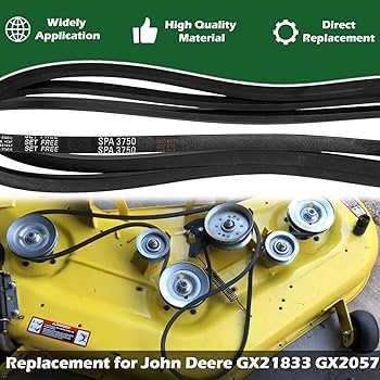
- Belts: Essential for transferring power between moving parts; regular checks are crucial for signs of wear.
- Blades: For cutting equipment, sharp and intact blades ensure effective operation.
- Battery: Regular inspection and replacement are vital for reliable starting and operation.
Being equipped with the right tools and understanding the necessary components for replacement can lead to efficient maintenance practices, extending the life and functionality of your machinery.
