john deere m655 parts diagram

To ensure efficient performance and longevity of your equipment, it is crucial to have a clear overview of how various elements interact with each other. Each element plays a specific role, and understanding their placement can help in maintaining and troubleshooting. The proper arrangement and connectivity of these parts provide stability and enhance overall functionality.

Identifying essential elements within the machinery can simplify routine maintenance and assist in identifying potential issues early on. A structured overview offers clarity on how individual components are linked, ensuring smoother operation and easier repairs when necessary.

In addition, visual representations of these mechanical setups enable users to swiftly navigate through the complexities of the system. With the right approach, even intricate systems become more manageable and understandable, allowing for timely interventions and adjustments.

John Deere M655: Comprehensive Parts Overview
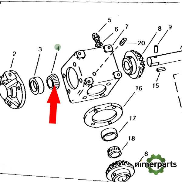
john deere m655 parts diagram

When maintaining a robust zero-turn model, understanding its intricate components is essential for ensuring long-term efficiency and performance. The machinery’s design integrates several key systems that work harmoniously, contributing to smooth operation across various terrains. This overview aims to highlight those integral elements, giving users insight into how each part plays a crucial role in the machine’s functionality.

Key Components and Their Functions

The machinery features a well-organized structure where each element has a specific function, supporting overall performance. From the drive system to the cutting mechanisms, each section operates efficiently to handle heavy-duty tasks. These components are engineered for durability, allowing the machine to endure challenging conditions.

Regular maintenance and timely replacements of essential elements can drastically improve both lifespan and reliability, making the machine a trusted tool for various applications. Understanding how these pieces fit together ensures smooth operation and prevents potential issues during intensive use.

Understanding the Mower Deck Components
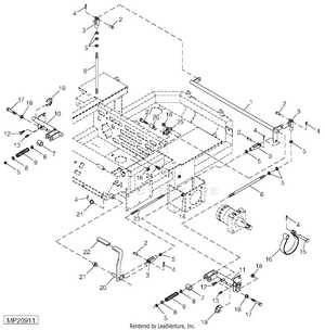
john deere m655 parts diagram

The mower deck is a critical part of any lawn care machine, ensuring a clean and even cut. It is designed with several key elements that work together to provide efficient performance. Each piece plays a role in delivering smooth operation and maintaining the overall quality of the mowing process.

Below is an overview of the essential components found in a typical mower deck, which contribute to its functionality and durability:

Engine Parts Breakdown for John Deere M655

Understanding the inner components of a powerful machine requires careful attention to how each element functions in unison. The main system responsible for generating power is built from various critical pieces, all contributing to the overall performance. By identifying the core elements within the engine, users can maintain and optimize its functionality.

Core Components and Their Roles

john deere m655 parts diagram

The engine consists of a variety of interconnected elements, including pistons, crankshaft, and valves, all working to ensure smooth combustion. Each piece plays a crucial role, from igniting fuel to managing exhaust flow, keeping the system running efficiently. Proper knowledge of these components helps in troubleshooting and improving longevity.

Maintenance and Replacement Tips

Regular inspection is essential for keeping these elements in good condition. Early detection of wear or damage can prevent costly repairs and extend the working life of the system. Replacement of worn-out components with quality alternatives ensures continued reliability and high performance.

Exploring the Hydraulic System Diagram

The hydraulic system plays a crucial role in ensuring the smooth operation of various components. It is responsible for transferring energy efficiently through fluid power, making it an essential aspect of any machinery that relies on controlled movement. Understanding the flow and connection of this system allows for better maintenance and troubleshooting when issues arise.

Main Components and Their Functions

john deere m655 parts diagram

  • Pumps: Responsible for creating pressure and directing fluid to different parts of the machine.
  • Valves: Control the flow of hydraulic fluid, allowing for precise adjustments to the system’s operations.
  • Cylinders: Convert the fluid power into mechanical force, enabling movements such as lifting or steering.
  • Filters: Ensure the hydraulic fluid remains clean, preventing damage to sensitive components.

Common Issues and How to Address Them

  1. Leaks: Check hoses and seals regularly to ensure there are no cracks or wear that could cause fluid loss.
  2. Pressure Drops: Monitor the pressure gauges and inspect for blockages or malfunctioning valves.
  3. Overheating: Ensure proper cooling mechanisms are in place to prevent the system from overheating during heavy use.

Key Electrical Components and Connections

john deere m655 parts diagram

Understanding the main elements of the electrical system is crucial for efficient operation and maintenance. These components ensure the proper functioning of various systems by distributing power, managing electrical flows, and protecting sensitive circuits from damage. By familiarizing yourself with these connections, you can troubleshoot issues more effectively and enhance the longevity of the equipment.

Main Power Source

john deere m655 parts diagram

The primary power source supplies energy to all essential systems. It plays a central role in maintaining electrical balance and ensures smooth operation under different conditions. Proper connection and regular inspection are necessary to avoid unexpected failures.

Control Modules and Wiring

john deere m655 parts diagram

Control modules regulate the distribution of electricity to specific areas. Wiring acts as a bridge, carrying current between different components. Ensuring the integrity of these connections is vital for preventing malfunctions and preserving the overall performance of the machinery.

Blade Assembly: A Detailed Look

john deere m655 parts diagram

The blade assembly is a crucial component that plays a significant role in the overall functionality of machinery designed for cutting and trimming. Understanding its structure and operation can greatly enhance maintenance practices and improve performance. This section delves into the various elements that constitute this assembly, highlighting their functions and interconnections.

At the core of the assembly lies the cutting blade itself, engineered for optimal efficiency and durability. The material composition and design of the blade ensure it withstands rigorous use while delivering precise results. Surrounding the blade, various mounting brackets and hardware secure it firmly, allowing for adjustments as needed to maintain cutting accuracy.

In addition, the assembly often features a spindle that facilitates rotation, enabling the blade to perform its cutting tasks effectively. Regular inspection and maintenance of these components are essential to prevent wear and tear, ensuring the assembly operates smoothly. Understanding each part’s role within the assembly will not only extend its lifespan but also enhance the overall productivity of the equipment.

Fuel System Components and Layout

The fuel system is a vital part of any machinery, ensuring that the engine receives the necessary fuel for optimal performance. Understanding the various components involved and their arrangement is crucial for efficient operation and maintenance. This section outlines the essential elements of the fuel system, emphasizing their roles and the overall layout.

At the core of the fuel system lies the fuel tank, responsible for storing the liquid fuel. This component feeds the fuel pump, which creates the necessary pressure to transport the fuel to the engine. The fuel filter is another key element, ensuring that impurities are removed before the fuel enters the engine, thus protecting sensitive components from damage.

The fuel lines serve as conduits, delivering the fuel from the tank to the engine. Their layout is designed to minimize bends and restrictions, promoting efficient flow. Additionally, the injectors atomize the fuel, allowing for a fine mist that enhances combustion. Proper alignment and functionality of these components are essential for reliable performance.

Understanding the arrangement and function of these elements enables operators to diagnose issues effectively and perform necessary maintenance, ensuring the machinery operates smoothly.

Steering Mechanism Overview

The steering system of this model is a crucial component that ensures precise maneuverability and control. It plays a vital role in the overall performance and responsiveness of the machinery, allowing operators to navigate various terrains effectively.

This mechanism consists of several key elements:

  • Steering Wheel: The primary interface for the operator, allowing for intuitive direction changes.
  • Linkage System: Connects the steering wheel to the wheels, translating the operator’s input into movement.
  • Gear Assembly: Reduces the effort needed to steer while enhancing the precision of the movement.
  • Pivot Points: Facilitate smooth turning and maneuvering by allowing parts to rotate freely.

Understanding the functionality of these components is essential for maintaining optimal performance and ensuring longevity. Regular checks and maintenance can prevent issues that may arise from wear and tear over time.

Transmission Parts and Their Functions

john deere m655 parts diagram

The transmission system plays a crucial role in ensuring smooth operation and efficient power transfer within machinery. Understanding the various components of this system is essential for optimal performance and maintenance. Each element contributes uniquely to the overall functionality, making it important to familiarize oneself with their roles and interrelationships.

Component Function
Blades Responsible for cutting the grass with precision.
Spindles Connect the blades to the deck and allow for rotation.
Component Function
Gearbox Regulates the speed and torque output to the wheels.
Clutch Facilitates engagement and disengagement of power transmission.
Shift Lever Allows the operator to select different speed ranges.
Drive Shaft Transmits power from the engine to the wheels.
Transmission Fluid Provides lubrication and cooling for smooth operation.

Brake System Components and Diagram

john deere m655 parts diagram

The braking mechanism plays a crucial role in the overall functionality and safety of machinery, ensuring effective stopping power and control during operation. Understanding the key elements of this system is essential for maintenance and troubleshooting. Each component contributes to the overall performance and reliability of the braking process, making it vital for operators to be familiar with their functions and interconnections.

In a typical braking assembly, several fundamental elements work together to facilitate smooth operation. The actuator initiates the braking process, translating force into movement. Additionally, brake pads and discs interact to create the necessary friction for deceleration. Hydraulic lines and reservoirs ensure that the fluid dynamics remain effective, while sensors may monitor system performance for optimal safety. Together, these components form a cohesive unit that is essential for reliable performance in demanding environments.

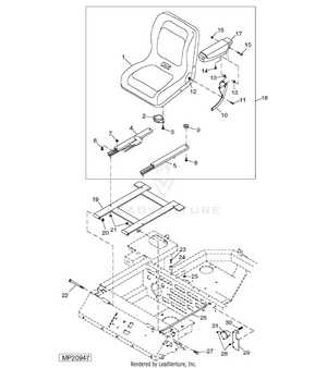
Seat and Operator Station Components

The operator’s environment is crucial for both comfort and efficiency during operation. This section delves into the various elements that contribute to the functionality and usability of the seating area and control center, ensuring an optimal experience for the user.

  • Seat: The primary component designed for the operator’s comfort, often adjustable to suit individual preferences.
  • Armrests: Provide support and enhance comfort, allowing for extended periods of operation without strain.
  • Control Panel: Houses various controls and indicators, offering easy access to essential functions.
  • Footrest: Ensures a stable platform for the operator’s feet, contributing to overall comfort during operation.
  • Seat Belt: Enhances safety by securing the operator in place while minimizing the risk of injury.
  • Dashboard: Displays critical information regarding machine performance, making it easier for the operator to monitor operations.
  • Steering Wheel: Facilitates precise maneuvering, ensuring smooth handling of the machine.

Each component plays a vital role in creating a cohesive and effective operator station, enhancing both safety and productivity during use.

John Deere M655 Maintenance Parts and Locations
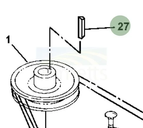
john deere m655 parts diagram

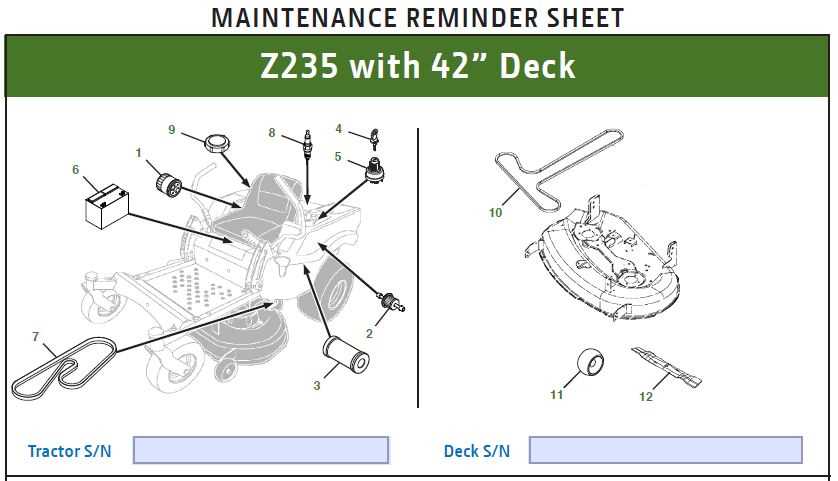
This section focuses on the essential components required for maintaining the equipment and their respective placements. Understanding where each element is located is crucial for effective upkeep and ensuring the machinery operates efficiently.

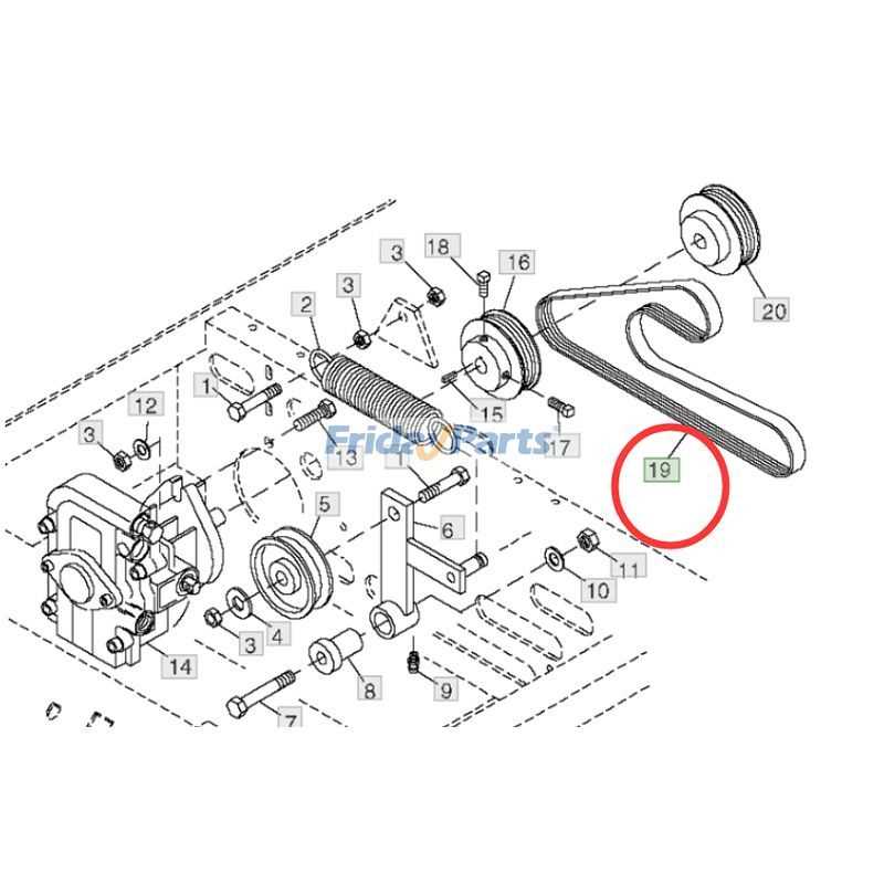
Key elements involved in routine maintenance include filters, belts, and lubricants. Each of these components plays a vital role in the overall functionality of the machinery. For instance, filters are typically situated in accessible areas to facilitate regular changes, while belts may be found in engine compartments, necessitating periodic checks to prevent wear and tear.

Additionally, lubrication points are strategically placed to allow for easy access during maintenance tasks. Regular inspections of these locations help identify any potential issues early, ensuring optimal performance and longevity of the machinery. Familiarity with these components and their placements will empower operators to perform maintenance tasks with confidence.