Mounting Points: Carefully positioned to ensure
Spindle and Hub Components
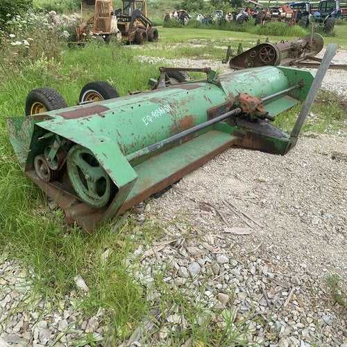
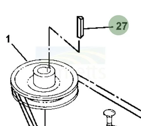
The spindle and hub assembly plays a crucial role in the overall functionality of mowing equipment. These components are designed to support the blade mechanism while ensuring smooth rotation and efficient cutting performance. Understanding their structure and operation is essential for proper maintenance and troubleshooting.
- Spindle: This is the central shaft that holds the cutting blades and allows them to rotate at high speeds.
- Hub: The hub connects the spindle to the blades, providing stability and support during operation.
- Bearings: Located within the spindle assembly, bearings facilitate smooth movement and reduce friction, extending the lifespan of the components.
- Seals: These components prevent dirt and debris from entering the spindle and hub assembly, protecting internal parts from wear and damage.
- Fasteners: Various nuts and bolts secure the spindle and hub to the mower deck, ensuring that all components remain firmly in place during operation.
Regular inspection and maintenance of the spindle and hub assembly are vital for optimal performance. Replacing worn bearings, seals, and fasteners can help avoid costly repairs and downtime.
Safety Shields and Guards
Ensuring the well-being of operators and bystanders is a crucial aspect of machinery design. Protective barriers and shields play a vital role in minimizing risks associated with moving parts and potential hazards. These components are essential for promoting a secure working environment.
Safety shields and guards serve several important functions:
- Prevent accidental contact with moving components.
- Reduce the risk of debris ejection that may cause injuries.
- Enhance visibility of operational areas while maintaining safety.
Regular inspection and maintenance of these protective features are necessary to ensure their effectiveness. Operators should adhere to the following best practices:
- Check for any signs of damage or wear on shields and guards.
- Ensure all protective components are securely attached before operation.
- Replace any damaged or missing shields promptly to maintain safety standards.
Incorporating reliable safety features significantly contributes to reducing accidents and enhancing operational efficiency. Proper use and maintenance of protective elements are essential for safe machinery operation.
Tailwheel and Axle Assembly
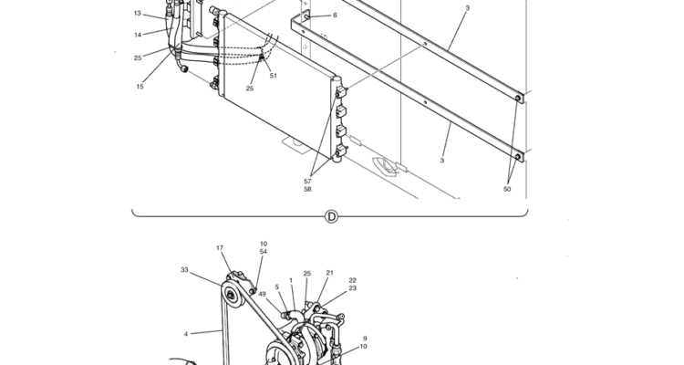
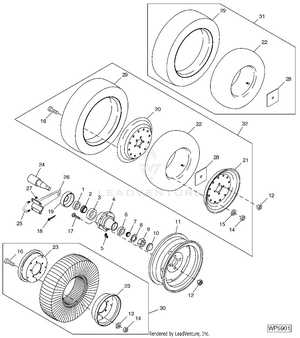
The tailwheel and axle assembly plays a crucial role in the functionality and maneuverability of various agricultural equipment. This component is designed to support the weight of the machinery while ensuring stability during operation and transport. Proper maintenance and understanding of its elements are essential for optimal performance.
At the core of this assembly is the axle, which serves as the central shaft that connects the tailwheel to the equipment. The tailwheel, typically designed for durability, aids in guiding the machine and preventing tipping. It is important to regularly inspect these components for wear and tear, as well as ensuring that all connections are secure.
In summary, maintaining the tailwheel and axle assembly is vital for enhancing the overall efficiency and safety of agricultural machinery. A well-functioning assembly not only improves performance but also extends the lifespan of the equipment.
Hardware and Fasteners Chart
This section provides a comprehensive overview of the essential components and securing mechanisms commonly found in agricultural machinery. Understanding the different types of fasteners and their specific applications can significantly enhance maintenance and repair processes.
Below is a detailed list of the various hardware elements utilized in these machines, including their specifications and typical uses:
- Bolts: These are crucial for joining two or more parts securely. They come in various grades and sizes, ensuring strength and reliability.
- Nuts: Paired with bolts, nuts are essential for maintaining tight connections. They often feature different thread types to match specific bolt sizes.
- Washers: Used to distribute load and prevent damage to surfaces, washers come in various thicknesses and materials, such as metal and rubber.
- Rivets: These permanent fasteners are ideal for applications where welding is not feasible. They provide a solid connection that is resistant to vibrations.
- Clips and Retainers: These components secure parts in place, preventing movement or dislodging during operation.
Utilizing the correct hardware and fasteners is vital for ensuring optimal performance and longevity of machinery. Regular inspection and replacement of worn or damaged components contribute to overall efficiency.
Adjustment and Tensioning Mechanisms
Properly calibrating and adjusting various components is crucial for optimal performance and longevity. This section focuses on the mechanisms responsible for maintaining the correct tension and alignment of key elements within the assembly. Understanding these adjustments can significantly enhance efficiency and reduce wear.
Importance of Proper Tension
Maintaining the appropriate tension in moving parts is vital for preventing excessive wear and ensuring smooth operation. Insufficient tension may lead to slippage, while excessive tension can cause premature failure. Regular inspection and adjustment of these mechanisms are essential for maintaining peak performance.
Adjustment Techniques
Several techniques can be employed to achieve the desired tension in the system. These methods often involve manual adjustments or the use of specialized tools designed to measure and apply the correct force.
| Adjustment Method |
Description |
| Manual Tension Adjustment |
Utilizing hand tools to tighten or loosen components for optimal tension. |
| Spring Mechanism |
Employing springs to automatically maintain tension through mechanical means. |
| Torque Measurement |
Using torque wrenches to ensure proper tightening of bolts and fittings. |
| Alignment Checks |
Regularly verifying the alignment of components to prevent uneven wear. |
Decal and Label Placement
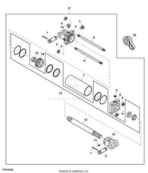
The positioning of decals and labels on machinery plays a crucial role in ensuring proper operation and safety. These markings provide vital information regarding maintenance, operation guidelines, and safety precautions, making it essential for users to understand their significance.
Importance of Correct Placement
Accurate placement of these indicators not only enhances visibility but also aids in quick reference during operation. Properly positioned decals can prevent misunderstandings and promote safe handling, thereby reducing the risk of accidents.
General Guidelines for Application
When applying decals, ensure that the surface is clean and dry to promote adhesion. Follow the manufacturer’s specifications regarding orientation and placement height. Additionally, regularly inspect the labels for wear and replace them as necessary to maintain clear communication of critical information.
Suspension and Linkage Elements
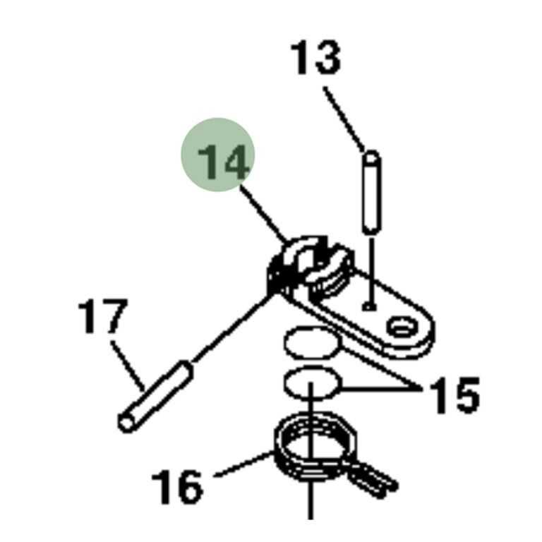
The suspension and linkage components play a crucial role in ensuring stability and maneuverability for agricultural machinery. These elements are designed to absorb shocks, maintain optimal ground contact, and provide seamless movement during operation. Understanding the configuration and functionality of these components is essential for efficient performance.
Key Functions
Suspension systems are responsible for minimizing the impact of uneven terrain on the machinery. This not only enhances operator comfort but also prolongs the lifespan of the equipment. Linkage systems, on the other hand, connect various components, facilitating smooth operation and control.
Common Components
Typical elements found in suspension and linkage setups include springs, dampers, and control arms. Each component serves a specific purpose, contributing to the overall effectiveness of the system.
| Component |
Function |
| Spring |
Absorbs shocks and maintains ride height. |
| Damper |
Controls oscillations and enhances stability. |
| Control Arm |
Connects wheel assemblies to the frame, allowing controlled movement. |
Common Replacement Parts Guide
This section provides an overview of frequently replaced components that ensure optimal performance and longevity of your equipment. Understanding these essential elements will help you maintain efficiency and reliability in your operations.
Here are some of the most commonly replaced components:
- Blades: Essential for cutting grass and other vegetation effectively. Regular replacement ensures clean and efficient operation.
- Belts: Vital for transferring power between moving parts. Worn belts can lead to decreased performance and potential damage.
- Filters: Crucial for maintaining clean oil and air circulation. Regular changes can prevent engine wear and improve efficiency.
- Hoses: Important for fluid transfer. Cracked or worn hoses can lead to leaks and operational issues.
- Bearings: Key for reducing friction in moving parts. Replacing worn bearings can enhance overall functionality.
By regularly inspecting and replacing these components, you can ensure your machinery operates at its best, reducing downtime and repair costs.
