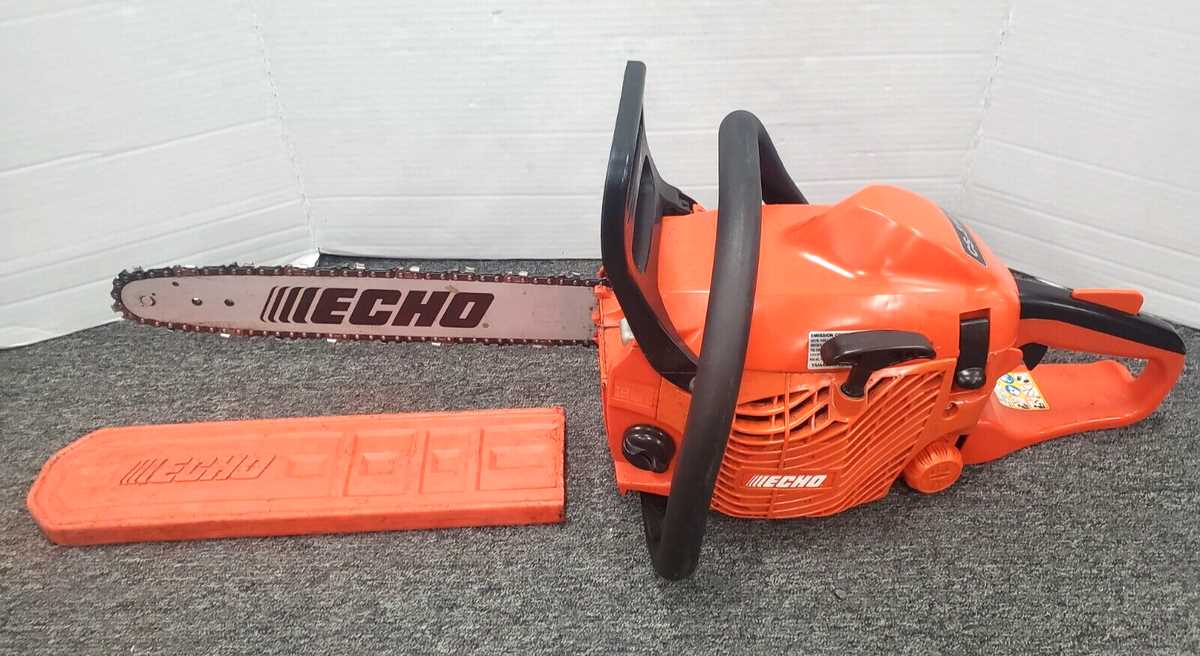
Maintaining the longevity and performance of your chainsaw requires a clear understanding of its internal structure. Recognizing the key elements involved in its operation will help ensure it runs efficiently over time. Each mechanism within the machine plays a crucial role in delivering the power and precision needed for various cutting tasks.
In this section, we will explore the essential components that contribute to the effective functioning of your tool. From the engine to the chain, each part is designed to work together, allowing smooth operation. Understanding how these elements interact can assist in both troubleshooting and routine maintenance.
Whether you’re looking to replace worn-out elements or simply want to understand your equipment better, this guide provides insights into the most important aspects of the machine’s internal structure.
Echo CS-310 Parts Overview

In this section, we will explore the essential components of a popular chainsaw model. Each element plays a critical role in ensuring smooth operation, from the engine to smaller, more intricate mechanisms. Understanding these various pieces helps in maintaining performance and prolonging the lifespan of the machine.
- Engine Assembly – The power source that drives the entire system, ensuring optimal cutting efficiency.
- Bar and Chain – Responsible for
Key Components of the Echo CS-310

Understanding the main elements of this chainsaw model is essential for efficient operation and maintenance. These components work together to ensure smooth performance, and knowing their functions can help with repairs and replacements when necessary.
Engine and Power System
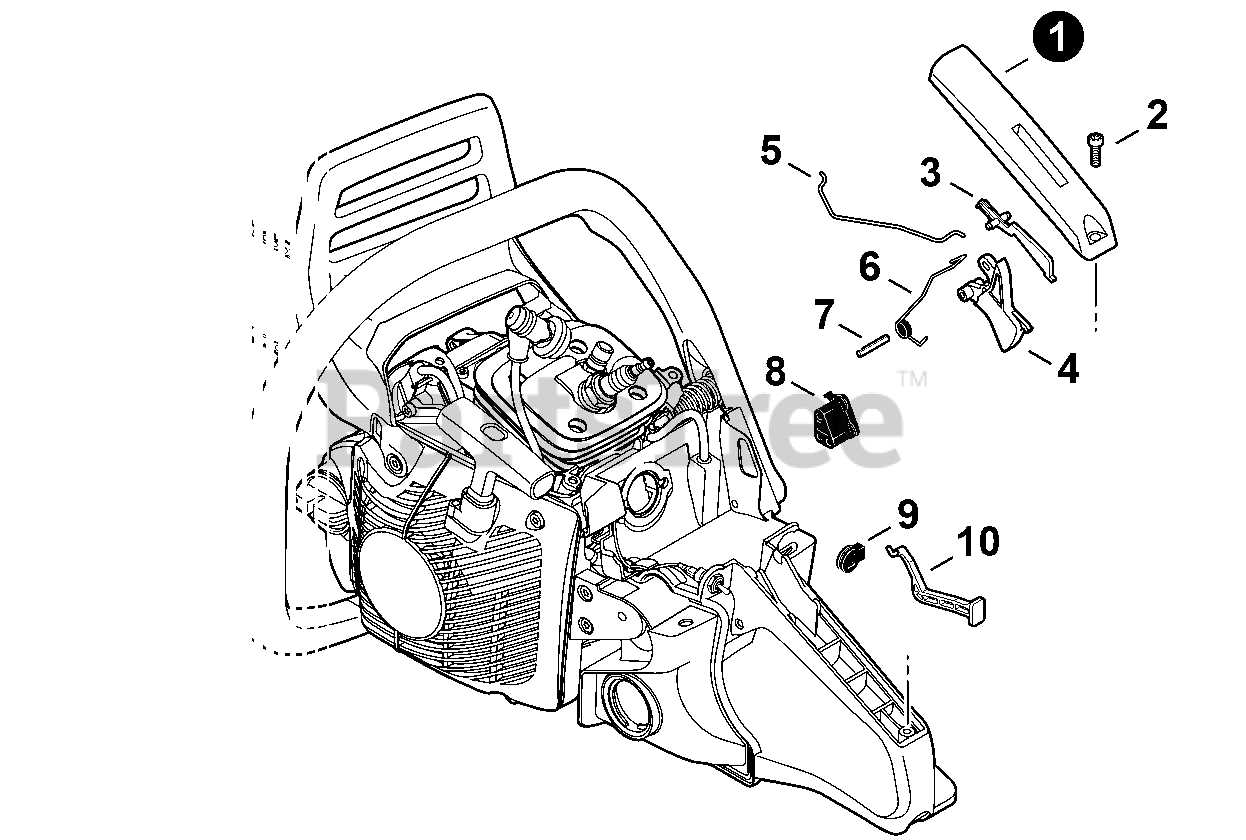
- Internal combustion mechanism designed for optimal power output
- Fuel reservoir and delivery system ensuring consistent energy supply
- Understanding the Chainsaw’s Engine Layout
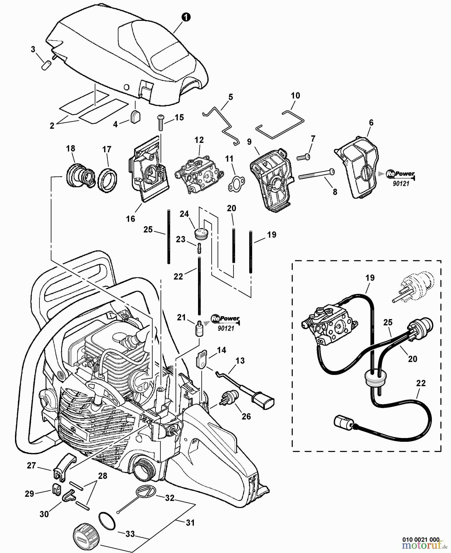
The structure of a chainsaw’s engine is designed to maximize performance while maintaining a compact and efficient form. The core components work together seamlessly, ensuring smooth operation during even the most demanding tasks. Grasping the basic engine layout helps in comprehending how each element contributes to the chainsaw’s overall functionality.
At the heart of the engine lies a powerful combustion system, which provides the
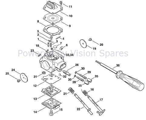
Fuel System Components Breakdown
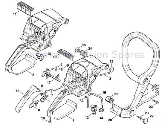
The fuel delivery system is a critical part of any equipment powered by an internal combustion engine. Its function revolves around efficiently supplying fuel to the engine, ensuring smooth operation. Understanding the various elements that make up this system can help maintain the overall performance and reliability of the machine.
Key components include the fuel tank, where the fuel is stored, and the fuel filter, which ensures impurities are removed before reaching the engine. The carbure
Guide Bar and Chain Assembly Details
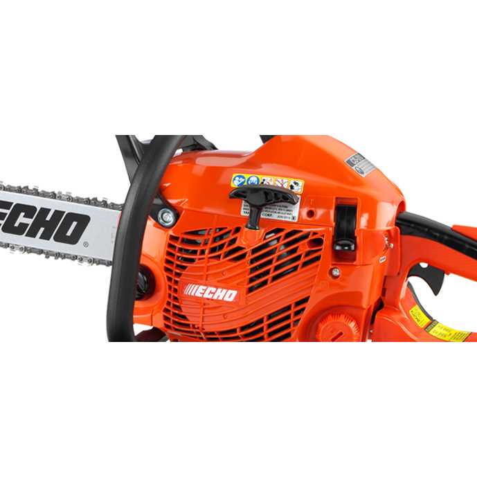
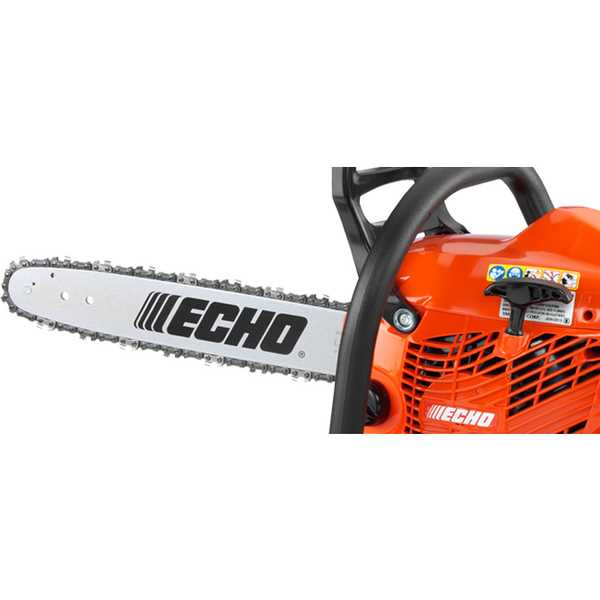
The guide bar and chain play a crucial role in the cutting system, ensuring smooth and efficient performance. Understanding how these components interact and function together is essential for maintaining proper operation. Their assembly requires attention to detail to ensure safety and optimal performance during use. In this section, we will explore the key elements and the installation process involved in assembling these components.
Main Components Overview
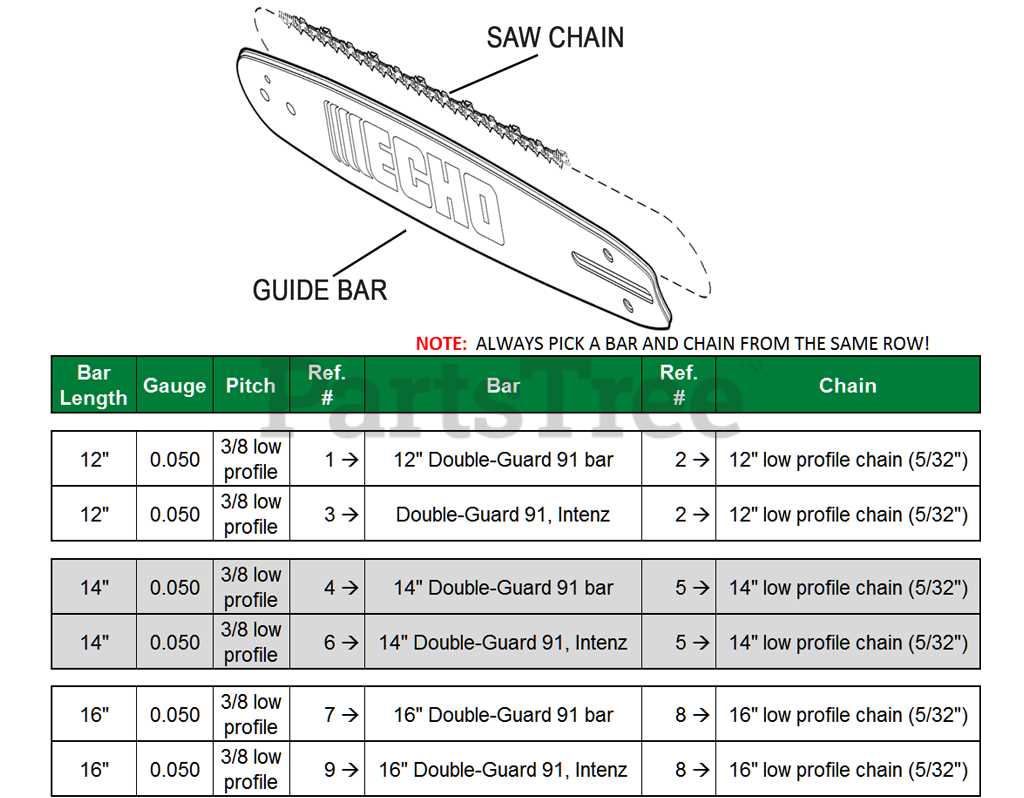
The primary components include the guide bar, which supports the chain during movement, and the chain itself, designed for cutting through various materials. Proper alignment and tension of the chain are critical to prevent accidents and ensure the longevity of the equipment. Ensuring correct assembly of these parts is vital for smooth functionality.
Installation Process
During installation, it is important to
Clutch and Sprocket Mechanism Explained
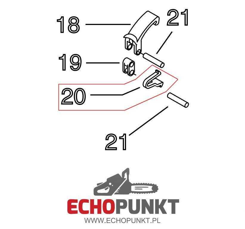
The clutch and sprocket system plays a crucial role in the functioning of various machines, enabling the transfer of power and motion. This mechanism allows for the controlled engagement and disengagement of components, ensuring efficient operation during different phases of performance. Understanding this system is essential for maintaining optimal functionality in equipment that relies on mechanical drive systems.
Functionality of the Clutch
The primary purpose of the clutch is to connect and disconnect the engine’s power to the drive system. By engaging the clutch, the operator can control when power is transmitted, allowing for smooth starts and stops. This mechanism utilizes friction to facilitate the connection, ensuring a gradual increase in speed and minimizing wear on other components.
Role of the Sprocket

The sprocket serves as a pivotal element in transmitting motion between the driving and driven components. Its design, featuring teeth that interlock with a chain or belt, allows for efficient power transfer. The interaction between the sprocket and the chain ensures that energy is conveyed seamlessly, contributing to the overall efficiency of the machinery.
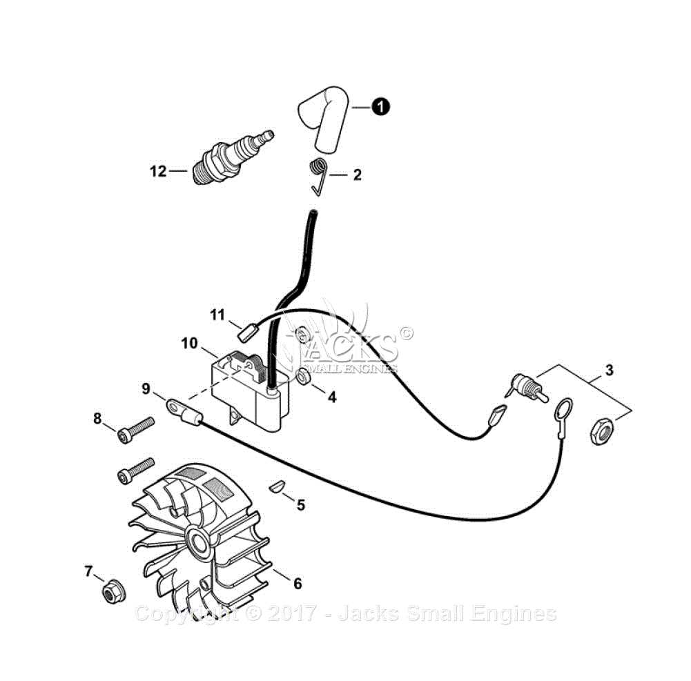
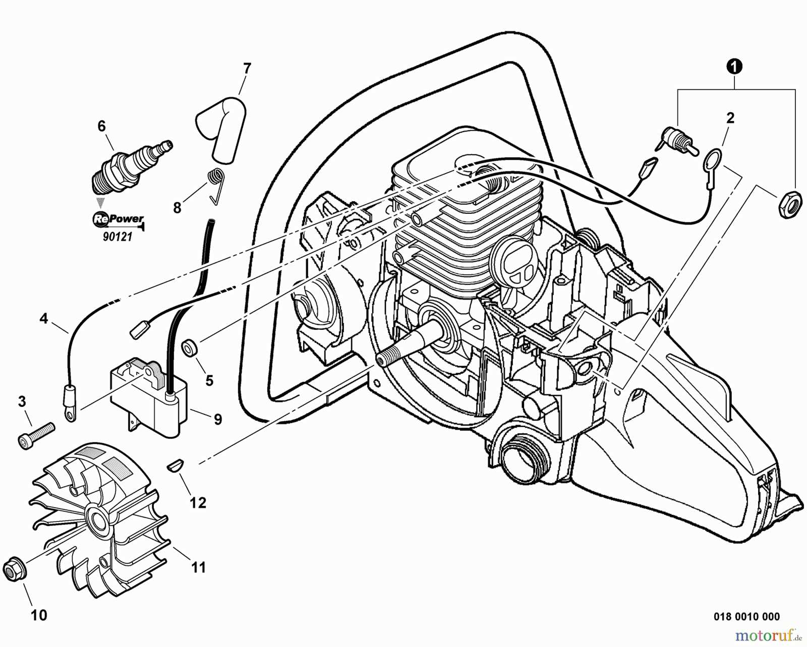
Ignition System Parts Overview
The ignition system is a critical component of any engine, responsible for initiating the combustion process. It consists of several essential elements that work together to create the necessary spark for igniting the fuel-air mixture. Understanding these components is vital for maintenance and troubleshooting.
Ignition Coil: This device transforms the battery’s low voltage into a high voltage needed to create a spark. It is a key player in the ignition process, ensuring that the engine starts smoothly.
Spark Plug: Positioned within the combustion chamber, the spark plug generates the spark that ignites the fuel mixture. Its efficiency can significantly affect engine performance and fuel economy.
Flywheel: This rotating component not only helps maintain engine momentum but also houses the ignition timing mechanisms, playing a crucial role in synchronizing the ignition process with engine cycles.
Ignition Module: Often an electronic component, the ignition module regulates the timing of the spark and controls the coil’s operation. It ensures that the ignition occurs at the optimal moment for maximum efficiency.
Each part of the ignition system contributes to the overall functionality of the engine. Regular inspection and maintenance of these components can prevent issues and enhance performance.
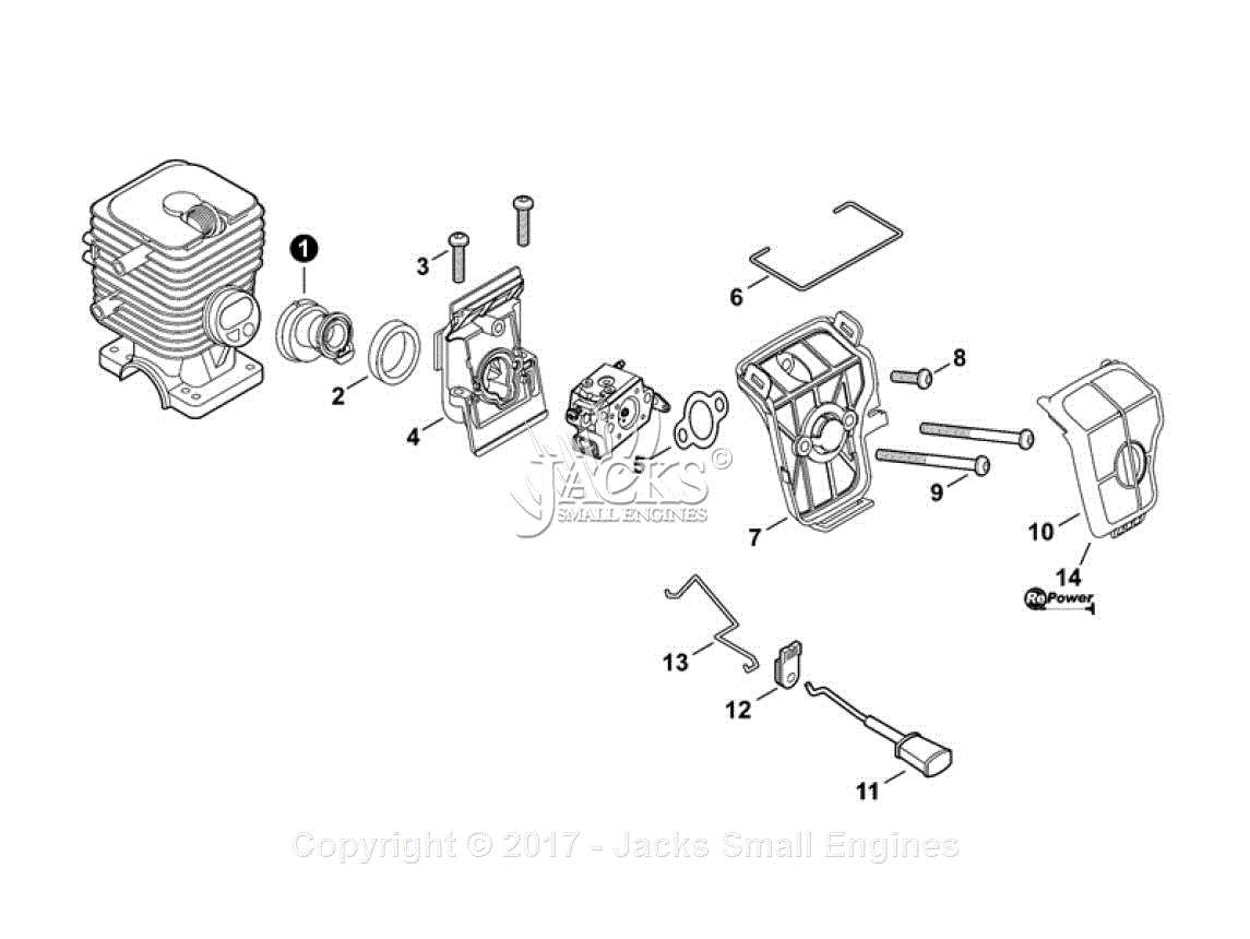
Air Filter and Carburetor Configuration
The effective operation of small engine machinery relies heavily on the optimal arrangement of the air filtration and fuel mixing systems. These components work in unison to ensure that the engine receives the right mixture of air and fuel, contributing to enhanced performance and longevity. Understanding how these elements are configured can significantly impact the overall functionality of the equipment.
Proper maintenance and adjustment of the air filter and carburetor are essential for peak performance. A clean air filter prevents debris from entering the engine, while the carburetor regulates the air-fuel mixture for efficient combustion. Below is a summary of key specifications related to these components.
Component Function Maintenance Tips Air Filter Traps dirt and particles to ensure clean air intake Clean or replace regularly based on usage Carburetor Mixes air and fuel in the correct proportions Inspect and adjust settings for optimal performance Handle and Throttle System Components
The handle and throttle assembly is essential for controlling the operation of various outdoor power tools. This system allows the user to manage speed and performance effectively, ensuring smooth handling during use. Understanding the individual elements that comprise this mechanism is crucial for maintenance and optimal functionality.
Component Name Description Grip The part held by the operator, providing comfort and control. Throttle Trigger Controls the engine speed and power output. Throttle Cable Connects the trigger to the engine, transmitting control signals. Handlebar Supports the grip and provides leverage for maneuvering. Safety Lock Prevents accidental activation of the throttle, ensuring user safety. Chain Brake and Safety Features

The chain brake and associated safety mechanisms play a crucial role in enhancing user protection during operation. These components are designed to minimize the risk of accidents by providing immediate response in case of kickback or unexpected movements. Understanding how these features function can significantly contribute to safer handling of the equipment.
The chain brake is an essential safety device that activates automatically when a sudden upward movement occurs. This feature prevents the chain from continuing to rotate, thereby reducing the likelihood of injury. Additionally, it can be manually engaged to provide extra security when the tool is not in active use.
Another critical safety aspect includes anti-vibration systems that help to reduce fatigue and maintain control. These systems are designed to absorb shocks and vibrations, ensuring a more comfortable experience for the operator. Incorporating these elements into the design reflects a commitment to safety and user-friendly operation.
In summary, understanding the importance of the chain brake and its safety features is vital for anyone operating this type of equipment. These mechanisms not only protect the user but also contribute to more effective and efficient operation, making safety a priority in tool design.
Starter Assembly and Recoil Mechanism
The starter assembly plays a crucial role in the ignition process of small engines. This mechanism enables the operator to initiate the engine’s functioning smoothly and effectively. Understanding the components involved and their interactions can greatly assist in troubleshooting and maintenance.
Components of the Starter Assembly
- Pull cord
- Recoil housing
- Starter pulley
- Spring
- Retaining screws
Each part contributes to the overall performance of the starter assembly. The pull cord, when tugged, engages the pulley system, which in turn initiates the engine crankshaft movement. The spring mechanism ensures that the cord retracts smoothly after use.
Function of the Recoil Mechanism
- Engagement of the engine
- Retracting the pull cord
- Providing resistance during the start
The recoil mechanism is designed to engage the engine while providing a smooth start. After the engine is ignited, it allows the cord to retract, preventing tangling and wear. Regular inspection of these components ensures optimal performance and longevity.
Maintenance Tips for Key Chainsaw Parts
Regular upkeep of essential components is crucial for ensuring optimal performance and longevity of your cutting tool. Proper care not only enhances functionality but also promotes safety during operation. By focusing on a few key areas, you can significantly improve the reliability of your equipment.
Cleaning the Air Filter: A clean air filter is vital for efficient engine operation. Remove debris and dust regularly to prevent airflow blockage. Depending on usage, consider replacing the filter at least once a season to maintain peak performance.
Sharpening the Chain: Dull chains can lead to increased wear on the engine and reduce cutting efficiency. Regularly inspect and sharpen the chain to ensure smooth operation. Use the appropriate tools and techniques to achieve the best results.
Inspecting the Bar: The guide bar is a critical component that requires periodic inspection. Look for signs of wear, such as grooves or damage. Regular lubrication helps maintain its integrity and prevents premature wear.
Checking the Fuel System: Ensure the fuel system is in good condition by examining hoses and connections for leaks or cracks. Use fresh fuel and mix it properly with oil to prevent engine issues.
Regular Maintenance Schedule: Establishing a routine maintenance schedule helps keep your tool in top shape. Document inspections and any required replacements to ensure nothing is overlooked. Consistency is key to prolonging the lifespan of your cutting equipment.
Replacement Guide for Worn Components
Maintaining the functionality of your equipment requires timely replacement of worn-out parts. This guide outlines the essential components that may need attention over time, ensuring that your machine operates smoothly and efficiently. Understanding which elements are prone to wear can help you make informed decisions about replacements.
Commonly Worn Components
- Blades
- Filters
- Belts
- Seals
- Spark plugs
Signs of Wear
Identifying signs of deterioration is crucial for maintaining optimal performance. Here are some indicators to watch for:
- Decreased efficiency during operation
- Unusual noises or vibrations
- Difficulty starting the machine
- Visible cracks or damages on components
By regularly checking for these signs, you can ensure that your machinery remains in top condition and avoid more extensive repairs in the future.