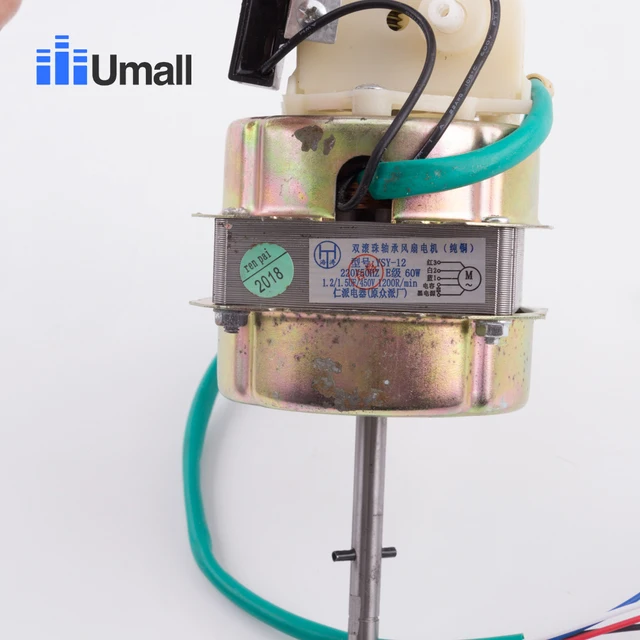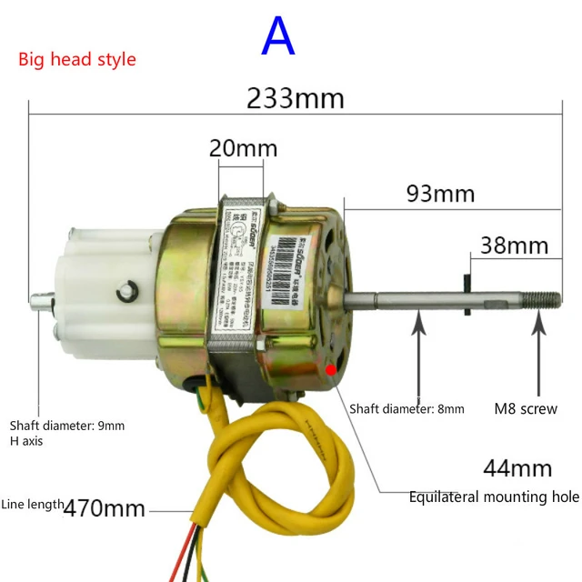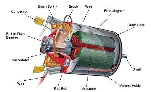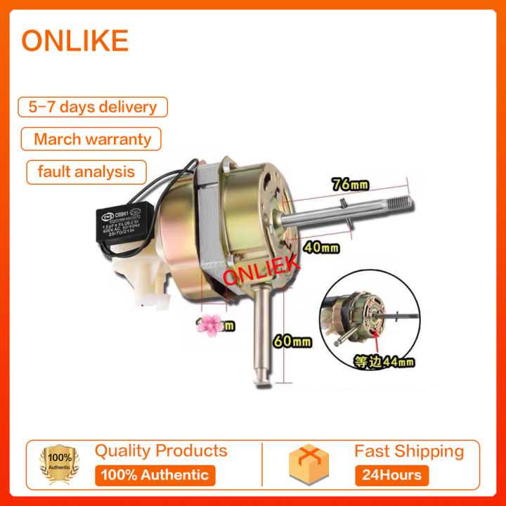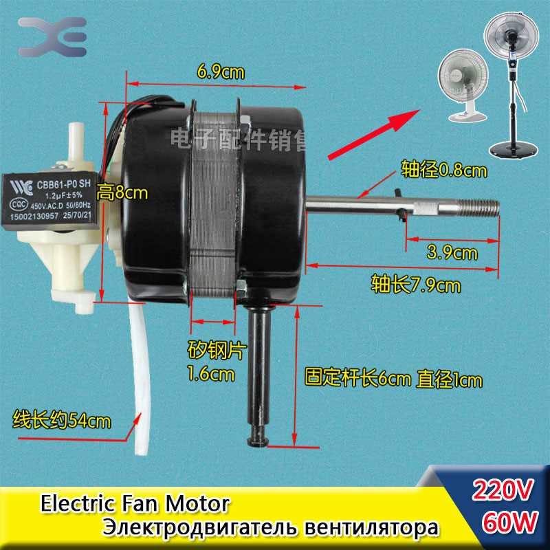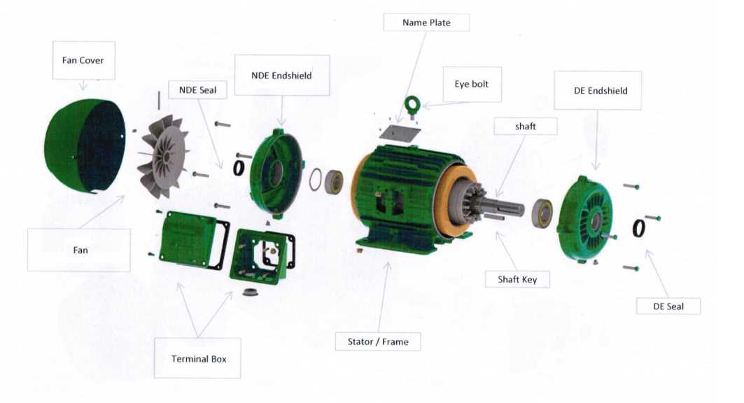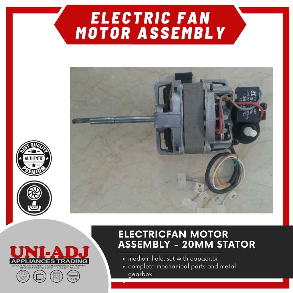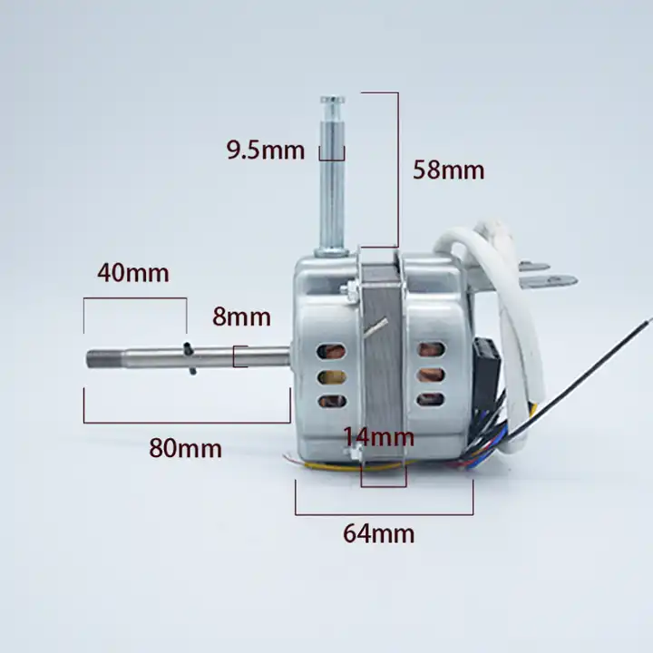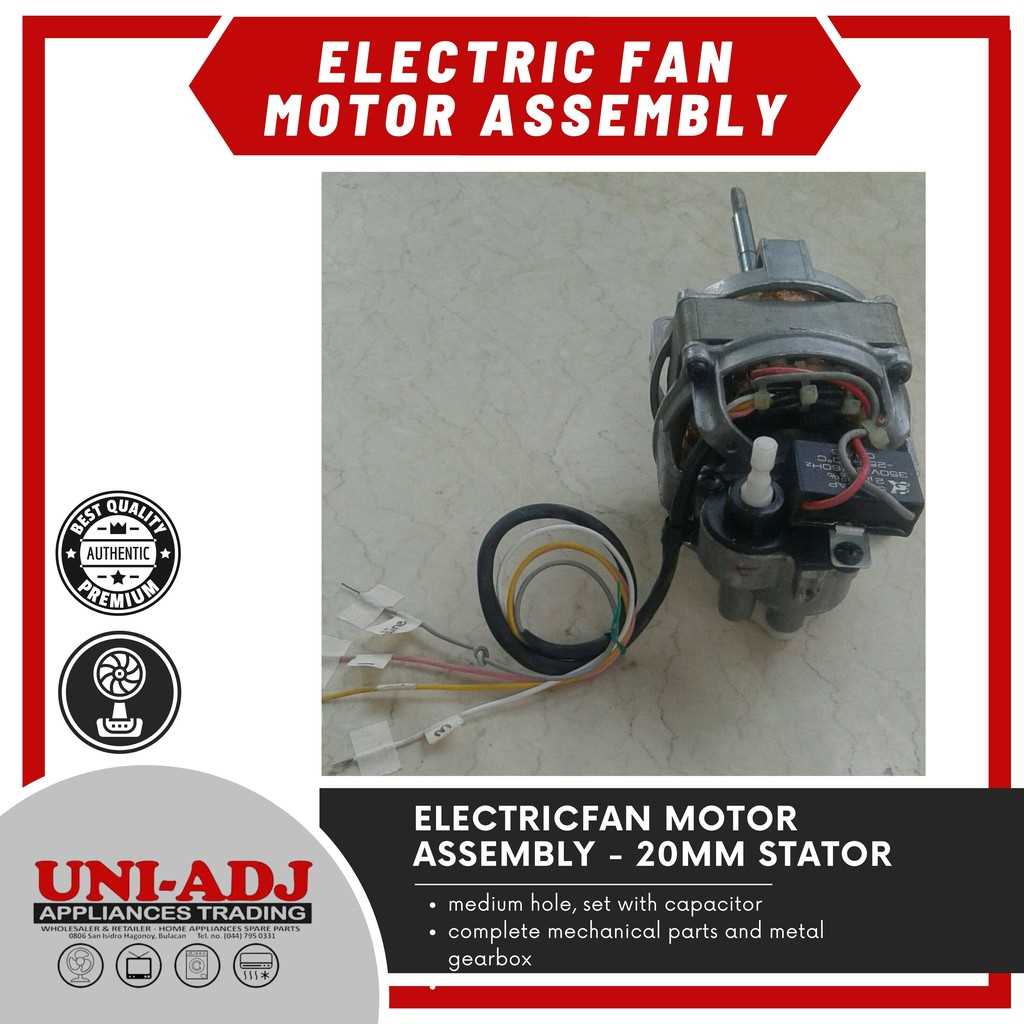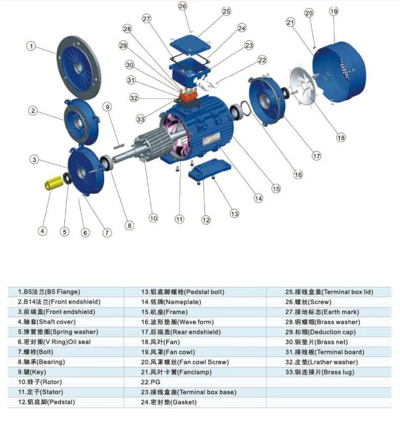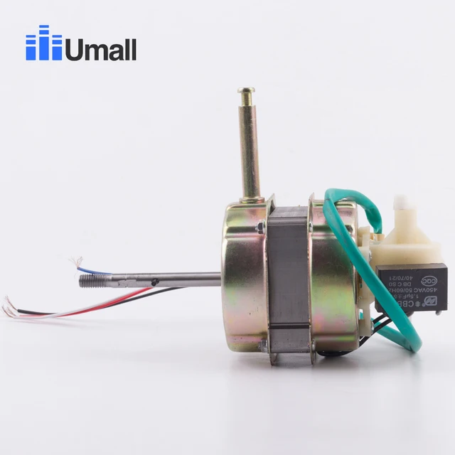
electric fan motor parts diagram

When it comes to mechanical cooling devices, their efficiency depends on several crucial elements working in harmony. These devices, designed to move air and regulate temperature, require a well-structured configuration to operate effectively. This guide focuses on the main components that make up such systems, outlining how they interact to ensure consistent airflow and performance.

The central mechanism of these systems relies on a combination of rotating and stationary elements, which convert electrical energy into mechanical movement. These components are meticulously designed to achieve balance, durability, and precision in performance. Understanding their function and relationship is essential for maintenance and troubleshooting.

From the dynamic core that drives the system to the connections and supports that stabilize it, each element plays a vital role. Identifying and understanding these key sections not only aids in repairs but also in enhancing overall efficiency and longevity of the device.

Electric Fan Motor Components Overview

Understanding the internal makeup of rotating airflow devices is key to ensuring optimal performance and longevity. These machines rely on various interconnected elements, each playing a crucial role in converting electrical energy into mechanical motion.

Key Elements of Fan Motor Design

electric fan motor parts diagram

The design of rotational airflow devices relies on several critical components to ensure smooth and efficient operation. Each element plays a unique role in maintaining the balance between energy consumption and performance. Understanding how these parts interact is essential for optimizing functionality and extending the lifespan of the unit.

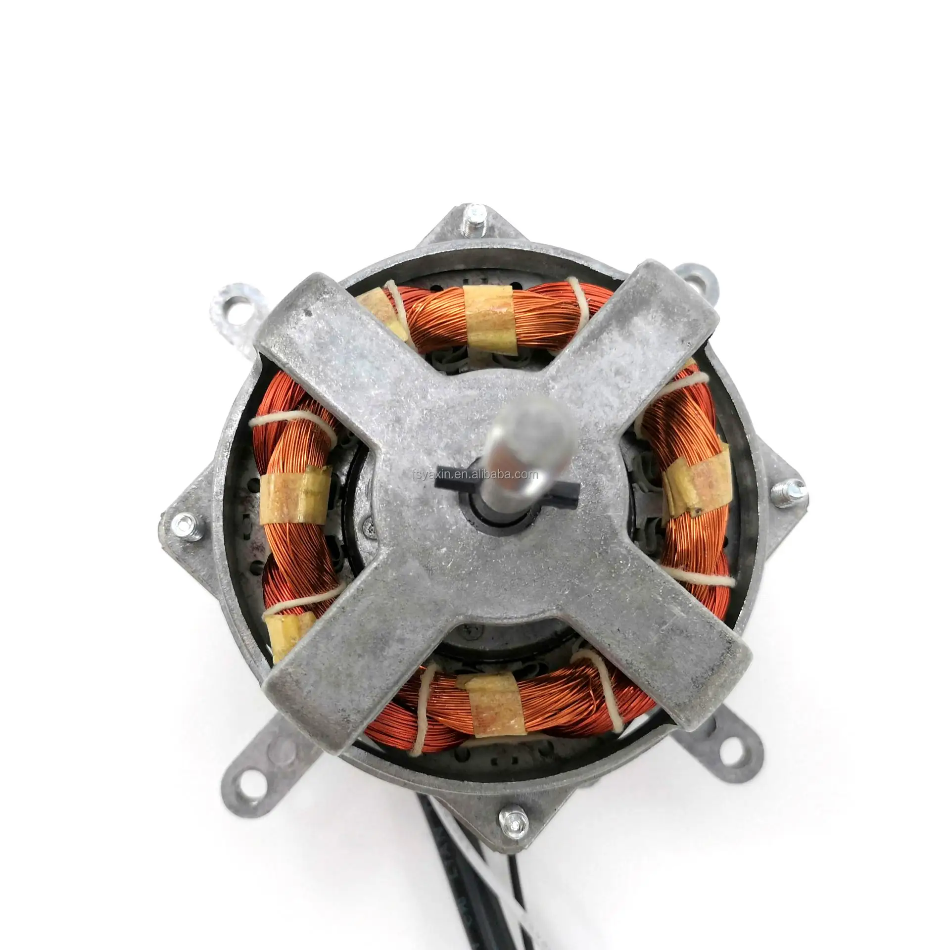
At the heart of the system lies the central rotor, which drives the movement through controlled magnetic forces. Surrounding this is a carefully arranged set of coils, responsible for generating the necessary electromagnetic field. Additional components, like bearings and casings, contribute to reducing friction and protecting internal mechanisms from external damage.

Understanding Motor Winding Configurations

electric fan motor parts diagram

Understanding the layout of coil arrangements is essential for grasping the performance and efficiency of rotary devices. These configurations determine how electrical energy is converted into mechanical movement, influencing power output, torque, and overall efficiency.

There are several ways to organize the wire coils within a device, and each method impacts its operation differently:

  • Series configuration: This setup involves connecting coils end-to-end, leading to higher torque at lower speeds.
  • Parallel configuration: In this arrangement, coils are connected side-by-side, allowing for increased speed but lower torque.
  • Compound configuration: A combination of series and parallel arrangements, offering a balance of speed and torque.

These winding methods are key factors in determining the performance and specific application of the rotating component.

Exploring the Role of the Rotor

The rotor is a vital component in devices that rely on rotational motion. Its movement is integral to generating mechanical power, transforming energy into the necessary motion to drive various systems. This key part works in tandem with other elements to ensure smooth operation, creating the foundation for efficient performance.

Interaction with the Stator

electric fan motor parts diagram

One of the rotor’s primary functions is its interaction with the stationary element, known as the stator. As the rotor rotates within the system, it creates a dynamic relationship with the surrounding components, producing the movement needed for optimal function. This interaction is essential for converting energy into continuous motion.

Contribution to Energy Conversion

electric fan motor parts diagram

The rotor’s ability to convert electrical energy into mechanical power is crucial. By spinning at high speeds, it facilitates the overall process, making it a cornerstone for systems that depend on sustained rotation. Its design and

Fan Motor Bearings and Their Function

electric fan motor parts diagram

Bearings are crucial components in various mechanical systems, ensuring smooth and efficient movement of rotating parts. These elements reduce friction, allowing for consistent motion and preventing unnecessary wear on surrounding elements. Properly functioning bearings help maintain stability and extend the life of the machinery.

Types of Bearings in Rotating Systems

electric fan motor parts diagram

There are several types of bearings used in different systems, including ball bearings and sleeve bearings. Each type serves a specific purpose, balancing the load and minimizing resistance during motion. Ball bearings provide excellent support for high-speed applications, while sleeve bearings offer quiet operation and durability.

Role in Performance and Longevity

The condition and quality of bearings directly impact the performance and lifespan of any rotating system. Well-maintained bearings reduce energy consumption and prevent overheating, ensuring the entire system operates efficiently. Regular maintenance and inspection are key to avoiding premature failure.

Capacitors in Electric Fan Motors

electric fan motor parts diagram

Capacitors play a crucial role in enhancing the efficiency and performance of various types of appliances that rely on rotating mechanisms. These components are integral to regulating electrical currents, ensuring smooth operation and optimal functionality. Their ability to store and release energy contributes significantly to the overall effectiveness of these devices.

Functionality of Capacitors

electric fan motor parts diagram

The primary function of capacitors is to store electrical energy temporarily, allowing for the smooth transition of current within the system. This capability is particularly beneficial during startup, as it provides the necessary boost to initiate movement. By stabilizing voltage levels, capacitors help maintain consistent performance throughout the operation of the appliance.

Types of Capacitors Used

electric fan motor parts diagram

Various types of capacitors are utilized in these applications, each serving specific purposes based on the design requirements. Common types include electrolytic and ceramic capacitors, which differ in their construction and energy storage capabilities. Selecting the appropriate type is essential for maximizing efficiency and ensuring long-term reliability.

How the Stator Powers the Motor

electric fan motor parts diagram

The component responsible for generating the primary magnetic field plays a crucial role in transforming electrical energy into mechanical movement. This essential element interacts with other components to facilitate the rotation needed for operation.

When alternating current passes through the windings of this component, it creates a rotating magnetic field. This field is vital for inducing motion in the adjacent elements, enabling the entire system to function efficiently.

Component Function
Rotor Converts electrical input into rotational motion.
Stator Produces the magnetic field that interacts with the rotor.
Function Description
Magnetic Field Generation Produces a rotating field that drives motion.
Induction Enables neighboring components to initiate rotation.
Stability Maintains consistent performance during operation.

Fan Blade Connection to Motor Assembly
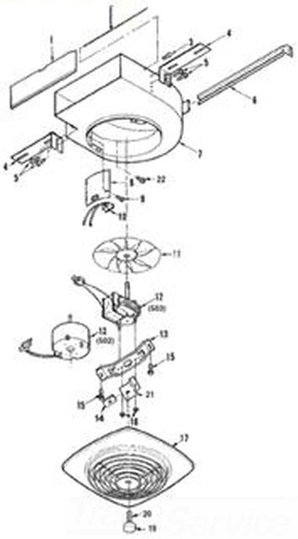
electric fan motor parts diagram

The integration of a rotating element with a driving mechanism is a crucial aspect of various appliances. This section explores how the blades are securely linked to the central unit, ensuring optimal performance and efficiency. A proper connection allows for the effective transfer of energy, contributing to the overall functionality of the device.

Understanding the Connection Mechanism
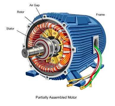
electric fan motor parts diagram

Establishing a robust connection involves specific components that facilitate the attachment and rotation of the blades. Typically, these elements include a hub, screws, and locking mechanisms, which together maintain stability during operation. The arrangement not only influences performance but also impacts the durability of the assembly.

Connection Types and Specifications

Different types of connections can be utilized depending on the design and purpose of the appliance. Here’s a table summarizing common connection types and their specifications:

Connection Type Description Application
Screw Connection Utilizes screws for secure attachment. Common in household units.
Snap Fit Components snap together for ease of assembly. Ideal for lightweight designs.
Interlocking Mechanism Features interlocking parts to enhance stability. Used in industrial models.

Impact of Housing on Motor Efficiency

electric fan motor parts diagram

The outer structure of a rotating device plays a crucial role in determining its overall performance and energy consumption. By providing protection and stability, this component can significantly influence how effectively the internal mechanisms operate. The design and materials used in constructing this enclosure can enhance thermal management and airflow, ultimately affecting the system’s efficiency.

A well-engineered casing minimizes vibrations and noise, contributing to a smoother operation. Additionally, the shape and size of the housing can affect the cooling characteristics of the unit. Adequate ventilation allows for better heat dissipation, preventing overheating and ensuring that the device maintains optimal performance levels over time. Thus, the right choice of housing is essential for maximizing efficiency and longevity.

Troubleshooting Common Motor Component Issues
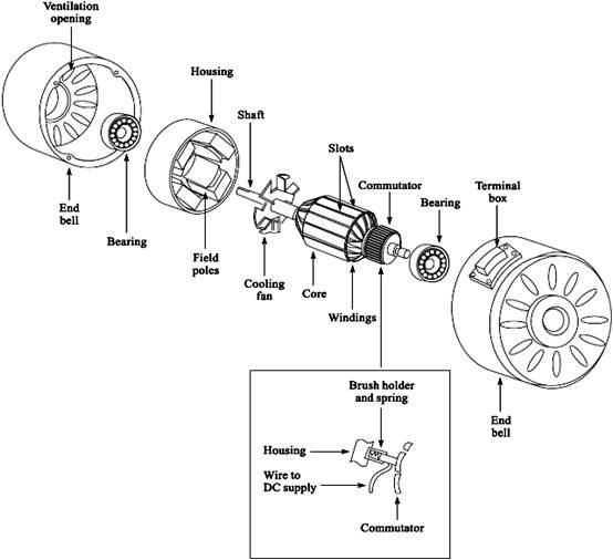
electric fan motor parts diagram

When dealing with issues related to the functionality of rotational devices, understanding the common problems that may arise is essential for effective resolution. This section explores typical challenges encountered with essential elements and provides guidance on identifying and addressing these complications.

One frequent concern is overheating, which can result from excessive load or inadequate ventilation. To resolve this, ensure that the assembly is not obstructed and that the airflow is unobstructed. Additionally, verify that the specifications of the current draw do not exceed the recommended limits.

Another common problem involves unusual noises, which may indicate wear or misalignment of key components. Inspect the configuration for any signs of looseness and replace any worn-out elements to restore smooth operation. Regular maintenance and checks can prevent such issues from escalating.

Finally, a lack of response or failure to initiate is often attributed to electrical faults or control system failures. Check connections and ensure that the supply voltage matches the required specifications. If issues persist, consider examining the control mechanisms for potential faults.