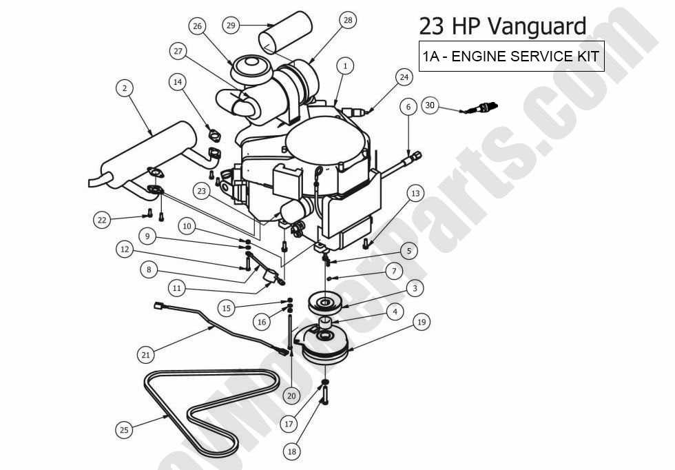
When working with a powerful piece of machinery, it’s essential to have a clear understanding of how its primary elements are organized and interact with each other. Each component has a specific role, contributing to the overall functionality and performance of the system. By gaining insight into how everything is laid out, maintenance and troubleshooting become much simpler tasks.
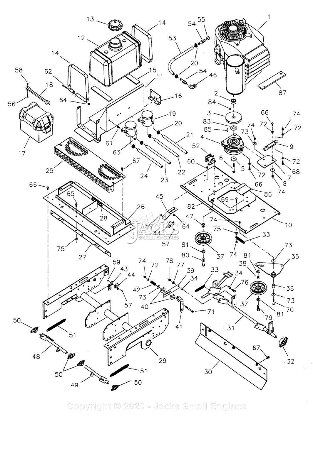
In this section, we will explore the arrangement of critical mechanical pieces, helping you identify their locations and roles. Whether you’re performing routine upkeep or trying to fix a specific issue, knowing the structure of these elements can be extremely helpful. This will ensure a smoother operation and longevity for the machine.
By familiarizing yourself with the structural layout, you’ll be better equipped to handle various tasks, from simple checks to more in-depth adjustments. Understanding how different sections connect and function together will make your work more efficient and effective.
Overview of Key Components
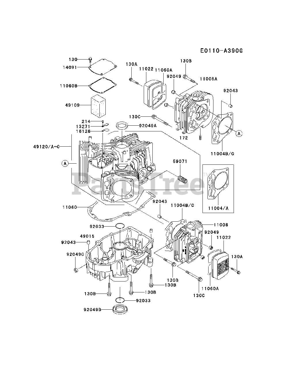
Understanding the essential elements within this system allows for better maintenance and performance optimization. By examining the fundamental components, one can grasp the overall function and identify areas requiring attention.
Core Assembly: The main structure is composed of interconnected parts that work together to deliver reliable performance. Each piece contributes to the system’s smooth operation, ensuring consistent output.
Cooling Mechanism: Effective temperature control is vital for preventing overheating. The cooling elements are designed to regulate heat, maintaining an optimal working environment for all internal components.
Fuel System: A well-maintained supply system ensures efficient power generation. It plays a critical role in delivering the right amount of energy, which drives the performance of the entire unit.
Electrical Connections: These ensure proper energy distribution throughout the system. Maintaining strong and secure connections is essential for avoiding interruptions and ensuring consistent functionality.
Understanding the Engine Block Layout
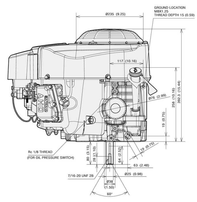
In this section, we’ll explore the structure and arrangement of the key components within the central housing of a typical motor. Understanding how these elements interact is crucial for ensuring smooth operation and maintenance. The layout of this core unit determines how efficiently power is generated and distributed throughout the system.
Key Structural Components
The central housing serves as the foundation, housing various important sections like the chambers, rotating elements, and supporting frameworks. These sections work together, transforming energy into motion. Each element within the structure plays a vital role in supporting performance and overall durability.
Flow and Functionality
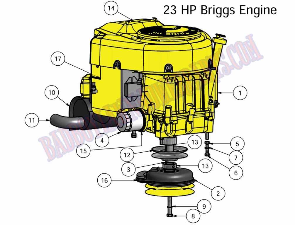
One of the key aspects to focus on is the flow of movement and how it impacts overall function. The precise alignment of components ensures that all processes run efficiently. Proper care and regular inspection of the internal layout will enhance longevity and reliability.
Exploring the Cooling System Mechanism
The cooling system is a critical component that ensures efficient temperature control within the machinery. It operates by maintaining optimal thermal levels, preventing overheating and allowing the internal processes to function smoothly over time. Understanding how this system works provides insights into its role in enhancing performance and longevity.
Heat Dissipation and Airflow
One of the primary functions of the cooling mechanism is to manage heat dissipation. This is achieved through a series of components that work together to circulate air, ensuring that excess warmth is quickly carried away from key areas. Proper airflow is essential for maintaining a stable operational environment, as it helps to balance the internal temperature.
Key Components of the System
The system relies on several critical parts that collaborate to regulate heat. These elements are responsible for both drawing in cooler air and expelling the heated air from the unit. Ensuring that each part functions efficiently is crucial for the overall effectiveness of the system,
Fuel System Components and Flow
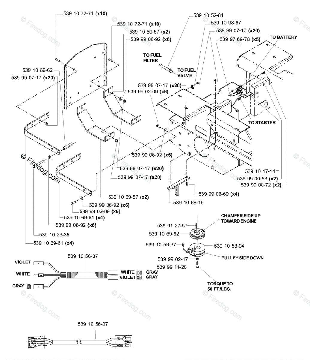
The fuel system is designed to efficiently manage the movement and distribution of fuel throughout the machinery. It plays a crucial role in maintaining consistent performance by ensuring that the fuel reaches the right places in the correct amounts. Understanding how the components work together can help in identifying potential areas for maintenance and optimization.
Primary Components
The key elements involved in the system are responsible for storing, filtering, and delivering fuel. A tank stores the supply, while a filter ensures impurities are removed before the fuel moves further. These components work in unison to provide a continuous, clean flow that keeps everything running smoothly.
Flow Process
The flow begins at the storage unit, where fuel is pumped through various stages before reaching its destination. Each stage is essential for maintaining the required pressure and cleanliness. By understanding this flow, one can easily troubleshoot any disruptions or inconsistencies that may arise during operation.
Detailed View of the Ignition Parts
Understanding the components that power the ignition system is crucial for ensuring proper functionality and smooth performance. This section provides a clear overview of the main elements involved in initiating the power process, focusing on their roles and connections.
Main Components Overview
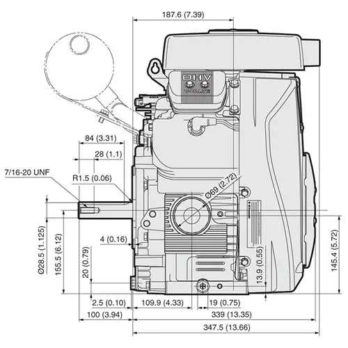
The ignition system is comprised of several key elements that work together to create the spark required for smooth operation. Each of these components has a distinct role, from generating power to delivering it efficiently. Proper alignment and connectivity of these elements are essential for optimal performance.
Connection and Functionality
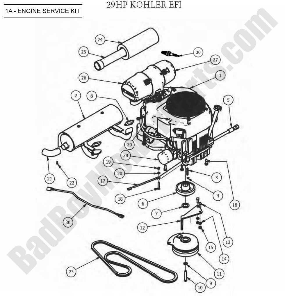
To ensure seamless ignition, it’s important to understand how these components are wired and how they interact with one another. A clear grasp of the wiring setup and signal flow allows for easy troubleshooting and maintenance, minimizing potential issues during operation.
| Component | Function | Notes |
|---|---|---|
| Spark Plug | Delivers the spark to the combustion area | Must
Air Intake and Filtration Setup
The air intake and filtration system is crucial for maintaining optimal performance and efficiency in small machinery. Proper air flow ensures that the combustion process runs smoothly, contributing to the longevity and reliability of the equipment. Understanding the components involved in this system helps users maintain and troubleshoot issues effectively. Key Components
Maintenance Tips
Lubrication System BreakdownThe lubrication system plays a critical role in ensuring the smooth operation and longevity of mechanical systems. This essential framework minimizes friction between moving components, thereby enhancing performance and preventing premature wear. A thorough understanding of its components and functionality can help in maintaining efficiency and reliability. Key Components of the Lubrication Framework
Functionality and Maintenance
Crankshaft and Piston FunctionalityThe interplay between the crankshaft and piston is fundamental to the operation of various machinery. These components work in tandem to convert linear motion into rotational force, enabling efficient power generation. Understanding their roles enhances comprehension of the overall mechanics involved in this process. Crankshaft OverviewThe crankshaft serves as a pivotal element in transforming the vertical movement of the piston into rotational motion. This conversion is crucial for the propulsion of the entire mechanism. Typically crafted from robust materials, the crankshaft is designed to withstand significant stress and torque during operation. Piston RoleThe piston operates within a cylindrical chamber, moving up and down as fuel ignites. This motion creates pressure that drives the crankshaft, facilitating energy transfer. Its design often includes rings that ensure a tight seal against the chamber walls, enhancing efficiency by minimizing gas leakage. Valves and Timing Mechanism Overview
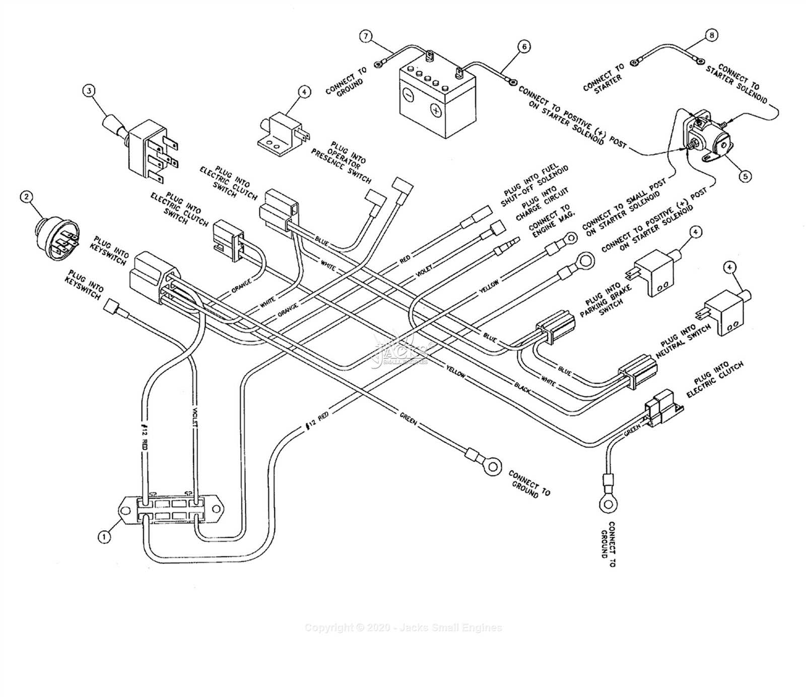
The operation of internal combustion systems relies heavily on a precise interplay of various components, particularly the mechanisms responsible for regulating air and fuel flow. This intricate balance ensures optimal performance and efficiency, directly impacting the overall functionality of the unit. Central to this process are the valves, which play a crucial role in allowing the necessary gases to enter and exit the combustion chamber at the appropriate intervals. The timing mechanism is equally vital, coordinating the opening and closing of these valves in harmony with the movement of the pistons. Together, these elements work to maintain a cycle that maximizes power output while minimizing waste. Understanding the construction and operation of these components is essential for troubleshooting and maintenance. Regular inspections can prevent potential issues that may disrupt the operation of the entire system. A thorough knowledge of the valve and timing system can enhance performance and extend the lifespan of the machinery. Electrical System and Wiring LayoutThis section provides a comprehensive overview of the electrical system and the associated wiring configuration for the specified small machinery model. Understanding the layout is crucial for effective troubleshooting, maintenance, and modification. Proper wiring ensures optimal performance and reliability of the entire system. Key Components of the Electrical System
Wiring Layout Overview
The wiring layout is designed to ensure that all components are interconnected efficiently. The following points outline the basic structure:
By familiarizing yourself with this electrical system configuration, you can enhance your ability to maintain and repair the machinery effectively. Exhaust System ConfigurationThe configuration of the exhaust system plays a crucial role in the overall performance and efficiency of the machinery. This assembly is designed to manage the flow of gases produced during operation, ensuring optimal expulsion while minimizing noise and emissions. Proper alignment and material selection are vital for maintaining durability and functionality. Typically, the exhaust system comprises several components, including headers, mufflers, and pipes. Each element must be carefully engineered to facilitate smooth gas flow and reduce back pressure. Attention to detail during installation and maintenance can significantly enhance the lifespan and performance of the setup. In addition, considering the design of the exhaust system can lead to improved fuel efficiency and reduced operational costs. Regular inspections and timely replacements of worn parts will contribute to a reliable and effective exhaust solution, ensuring that the machinery runs at its best. Engine Mounting and Vibration Control
Proper installation and stability of mechanical systems play a crucial role in performance and longevity. The way components are secured and their ability to absorb disturbances significantly impact overall functionality. Ensuring that these systems are adequately mounted can prevent excessive wear and potential failures. Vibration management is essential for enhancing operational efficiency. Uncontrolled oscillations can lead to structural fatigue and compromise the integrity of surrounding components. Incorporating appropriate dampers and mounts can effectively mitigate these effects, providing a smoother and quieter experience. Additionally, strategic placement of support structures is vital. It not only enhances balance but also ensures that forces are evenly distributed, reducing the risk of stress concentration in specific areas. Attention to detail in these aspects contributes to optimal performance and durability of the assembly. |
