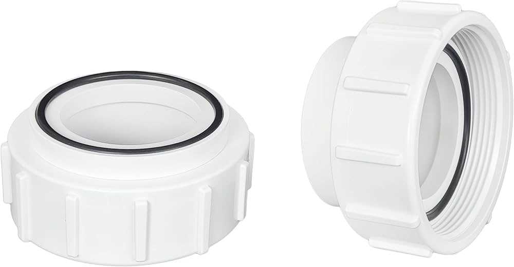
When maintaining a heating system, it’s crucial to have a clear understanding of the essential elements that contribute to its overall function. Knowing how various elements work together ensures the longevity and efficiency of the system, allowing for timely interventions and repairs when needed. By familiarizing yourself with the layout and connections, you can enhance the performance of your equipment.
Each unit relies on multiple interconnected elements that help regulate temperature and ensure smooth operation. These elements are designed to withstand a range of conditions and can often be replaced or repaired to restore optimal functionality. Proper identification of these critical components is key to addressing any issues effectively.
In this section, we’ll delve into the most important aspects, helping you navigate the various features and ensure smooth operation. Whether you’re looking to improve energy efficiency or address specific concerns, understanding these elements is an essential part of maintaining your system.
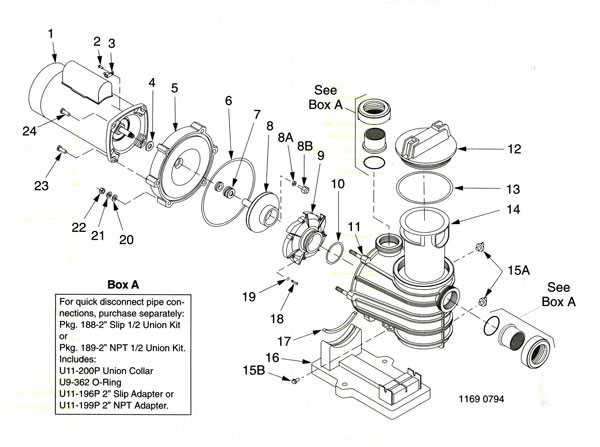
Overview of Sta Rite Heater Components
The device responsible for maintaining an optimal temperature in water systems is composed of various interconnected elements. These elements work together to ensure smooth operation, from controlling water flow to regulating temperature levels.
Key Mechanical Elements include the flow control system and pressure valves. These components ensure that water moves at the correct rate, and any excess pressure is properly managed, maintaining system balance.
Temperature Regulation Mechanism is at the heart of the system. It involves sensors and thermostats that monitor the heat levels, adjusting them based on user settings to provide consistent warmth.
The entire setup is designed for both efficiency and durability, ensuring long-lasting performance even under high demand. Each component plays a crucial role in maintaining the overall function of the system.
Key Internal Elements of the Heater
The inner workings of this equipment involve various critical components that work together to ensure efficient operation. Each part plays a specific role in maintaining proper function, heat regulation, and safety. Understanding these elements is crucial for optimal performance and troubleshooting potential issues.
Core Components and Their Functions
At the heart of the unit are several essential elements responsible for generating and distributing warmth effectively. These components collaborate to maintain balance, control temperatures, and ensure safe operations.
- Burner Assembly: This part is responsible for igniting and maintaining the flame, which heats the water or air.
- Heat Exchanger: Transfers the warmth from the combustion process to the medium being heated, maximizing efficiency.
- Control Module: Monitors the temperature and manages the ignition sequence to maintain consistent warmth.
- Pressure Switch: Ensures that the system only operates when adequate airflow is present, protecting against malfunctions.
Supporting Elements
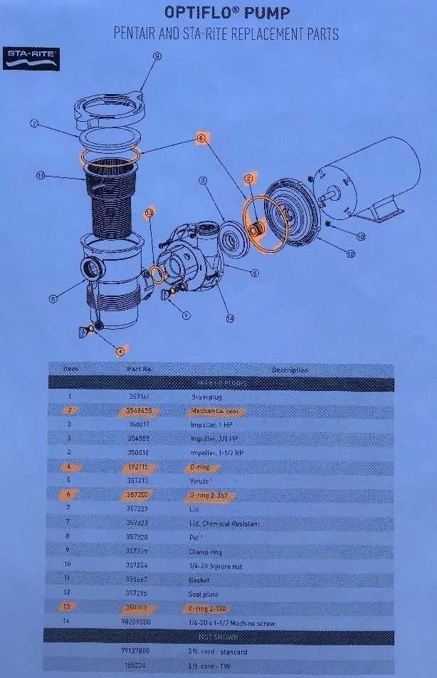
In addition to the core elements, supporting parts contribute to the safety and long-term durability of the system.
- Thermostat: Regulates the desired temperature, allowing for adjustments based on user preferences.
- Safety Sensors: Detect abnormal conditions like overheating or gas leaks, shutting down the system to prevent accidents.
- Ventilation Fan: Helps in expelling harmful gases produced during combustion, ensuring a clean and safe environment.
Burner Assembly and Its Functions
The burner assembly plays a crucial role in the overall operation of the heating system. This component ensures the proper ignition and distribution of fuel, which is essential for generating the required heat. Understanding its structure and functions is key to maintaining efficiency and safety in the unit.
Main Components of the Burner Assembly
- Burner Tubes: Responsible for directing the fuel and air mixture into the combustion area.
- Ignition System: Initiates the combustion process by providing a spark or flame.
- Gas Valve: Regulates the flow of gas to the burners, ensuring proper combustion levels.
- Flame Sensor: Monitors the presence of a flame to prevent unburned fuel from accumulating.
Key Functions of the Burner Assembly
- Fuel Combustion: The assembly combines fuel with air, igniting the mixture to produce heat.
- Heat Transfer: Generated heat is then transferred to the heat exchanger, which distributes it to the surrounding area.
- Safety Mechanisms: Includes sensors and controls to ensure safe operation, shutting down the system in case of malfunctions.
Understanding the Heat Exchanger Role
The heat exchanger is a critical component in many heating systems, responsible for transferring energy from one medium to another. Its purpose is to ensure that warmth is efficiently distributed without direct contact between the heat source and the heated area. This process allows for controlled temperature regulation while maintaining the system’s overall safety and functionality.
Energy transfer occurs when the exchanger absorbs heat from a source and passes it through a medium, such as water or air, which can then be used to warm a space or a fluid. The effectiveness of this process depends on the exchanger’s design and materials, which are optimized for thermal efficiency and durability.
Maintaining the integrity of the heat exchanger is essential to prevent issues such as overheating or energy loss. Regular inspection ensures that the system runs smoothly, minimizing wear and prolonging the life of the equipment.
Control Board and Wiring Diagram
The control board plays a crucial role in managing the functions of various components, ensuring proper operation and communication between different parts of the system. It serves as the central hub for processing signals and executing commands based on user inputs and sensor data.
Connections and Wiring Overview
The wiring system connects the control board to multiple sensors and devices, enabling seamless data flow and control signals. Each wire has a specific function, whether it’s powering components or sending data from sensors back to the board for further processing. Ensuring accurate wiring is critical for the system to perform correctly.
Troubleshooting the Control Board
If issues arise, inspecting the wiring connections and the control board itself is a common first step. Loose or damaged wires can lead to miscommunication, resulting in malfunctions or failure of certain operations. Proper diagnosis involves checking each connection point and ensuring the control board is receiving and processing the necessary signals.
Ignition System Breakdown
The ignition system plays a crucial role in initiating the combustion process within various heating units. Understanding its components and functionality is essential for effective maintenance and troubleshooting. This system ensures that the fuel-air mixture ignites at the right moment, facilitating optimal performance.
At the heart of the ignition system lies the spark generator, which produces the necessary spark to ignite the fuel. This component is typically triggered by a control module that detects the appropriate conditions for ignition. In addition, ignition wires connect the generator to the combustion chamber, transmitting the spark efficiently.
Another vital part of the system is the electrode assembly, where the spark actually occurs. This assembly must be maintained properly to ensure reliable ignition. Over time, buildup of residues can hinder performance, making regular inspections crucial.
In summary, the ignition system is integral to the overall efficiency of heating devices. Understanding its individual components can help users diagnose issues and maintain optimal operation.
Pressure Switch and Its Importance
The pressure switch is a crucial component in various heating systems, serving as a safeguard for safe operation. It detects changes in pressure levels, ensuring that the system functions within specified parameters.
Functionality: This device activates or deactivates the system based on the detected pressure. If the pressure falls below or exceeds predetermined limits, the switch triggers a response, preventing potential hazards.
Significance: A malfunctioning pressure switch can lead to system inefficiencies, unsafe conditions, or even complete shutdowns. Regular maintenance and timely replacement of this component can enhance reliability and prolong the life of the entire system.
Conclusion: Understanding the role of the pressure switch is essential for anyone involved in the maintenance or operation of heating systems. By ensuring proper functionality, users can enhance safety and efficiency in their heating solutions.
Manifold Assembly Overview
The manifold assembly plays a crucial role in the overall functionality of combustion devices, facilitating the proper distribution of fuel and air mixture to various components. Understanding its design and components is essential for effective maintenance and troubleshooting.
Key Components
- Body: The main structure that houses other parts and supports the entire assembly.
- Inlet: The section where the fuel and air enter the assembly for processing.
- Outlet: Directs the prepared mixture to the burner area for ignition.
- Valves: Control the flow of fuel and air, ensuring optimal performance and safety.
- Seals: Prevent leaks and maintain the integrity of the assembly.
Functionality
The manifold assembly ensures that the correct proportions of air and fuel are mixed and delivered efficiently. This process is vital for achieving proper combustion and maximizing energy output while minimizing emissions. Regular inspection of the manifold assembly is recommended to maintain operational efficiency and safety.
Gas Valve Configuration
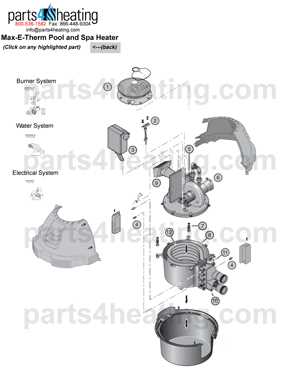
The arrangement of the gas control unit plays a crucial role in the overall functionality of any combustion system. Understanding how this component interacts with other elements is essential for effective maintenance and troubleshooting. Proper alignment and settings ensure efficient operation, minimizing risks associated with gas flow.
Key Features:
- Flow Regulation: The gas control unit is designed to manage the flow of fuel, ensuring optimal performance.
- Pressure Control: It maintains the necessary pressure levels, which is vital for safe and efficient operation.
- Safety Mechanisms: This component often includes features that prevent leaks or overpressure conditions, enhancing safety.
For maintenance, it’s important to regularly inspect connections and settings. Any misalignment or damage can lead to inefficiencies or safety hazards. By adhering to proper configuration guidelines, users can ensure reliable and safe operation of their gas systems.
Temperature Sensors and Thermistors
Temperature sensors and thermistors play a crucial role in monitoring and regulating thermal conditions in various devices. These components are essential for ensuring optimal performance and energy efficiency, as they provide real-time feedback on temperature variations.
Functionality of Temperature Sensors
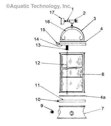
Temperature sensors operate by detecting changes in temperature and converting them into electrical signals. This process allows for precise monitoring and control of heating or cooling mechanisms. Different types of sensors are used depending on the application, each offering unique advantages in terms of response time, accuracy, and range.
Characteristics of Thermistors
Thermistors are a specific type of temperature sensor characterized by their resistance change in response to temperature fluctuations. They are commonly used for their high sensitivity and accuracy over a limited temperature range. Depending on their construction, thermistors can be classified as either NTC (Negative Temperature Coefficient) or PTC (Positive Temperature Coefficient), each serving different purposes in thermal management systems.
| Type | Characteristics | Applications |
|---|---|---|
| NTC Thermistor | Resistance decreases as temperature increases | Temperature measurement, circuit protection |
| PTC Thermistor | Resistance increases as temperature increases | Overcurrent protection, self-regulating heating elements |
Fan Assembly and Airflow Control
The fan assembly plays a crucial role in maintaining optimal temperature regulation within a system. Its primary function is to circulate air effectively, ensuring consistent airflow and heat distribution throughout the environment. A well-designed airflow control mechanism enhances efficiency, allowing for precise management of temperature and humidity levels.
Components of the Fan Assembly typically include a motor, blades, and housing, all working together to generate airflow. The motor drives the blades, creating a pressure difference that pulls air through the system. This movement facilitates the exchange of warm and cool air, contributing to a balanced atmosphere.
Airflow Control Mechanisms are essential for adjusting the direction and volume of air movement. Various methods, such as adjustable louvers or dampers, can be employed to guide airflow where it is needed most. These controls allow for customization based on specific requirements, optimizing performance and energy consumption.
Regular maintenance of the fan assembly and its airflow control features is vital for ensuring longevity and functionality. Keeping components clean and well-lubricated minimizes wear and tear, enhancing efficiency. Furthermore, timely inspections can identify potential issues before they escalate, ensuring uninterrupted operation.
In summary, the synergy between the fan assembly and airflow control is integral to the overall effectiveness of climate management systems. Understanding their functions and maintenance needs leads to improved performance and user satisfaction.
Troubleshooting Common Heater Part Failures
Identifying and resolving issues with heating devices can significantly enhance their performance and longevity. Various components may malfunction due to wear, misuse, or environmental factors. Understanding the common failures and their symptoms allows users to take proactive measures for repair and maintenance.
Here are some typical failures and their potential causes:
| Component | Common Symptoms | Possible Causes |
|---|---|---|
| Thermostat | Inconsistent temperatures, device not turning on | Faulty calibration, electrical issues |
| Fan | Unusual noises, lack of airflow | Obstructions, motor failure |
| Power Supply | No power, tripped circuit breaker | Wiring issues, blown fuses |
| Heating Element | Device not heating, strange odors | Burnt out, debris buildup |
Addressing these failures promptly can restore functionality and improve safety. Regular inspections and maintenance can help prevent these issues from arising in the first place.