Understanding the mechanical structure of agricultural machinery is crucial for efficient maintenance and repair. In this section, we will delve into the intricate systems that drive essential farming equipment, allowing you to gain insight into the inner workings and functionality of various mechanical elements. This guide serves to help identify and analyze different assemblies that contribute to the overall performance.
Every element plays a vital role in ensuring the smooth operation of farming tools. From power transmission mechanisms to control systems, each part works in unison to achieve optimal functionality. Here, we’ll explore the key sections that require regular inspection and attention to maintain high performance standards.
This detailed look into the mechanical framework will provide a clearer understanding of how different components interconnect, offering a roadmap for proper upkeep and troubleshooting.
Machine Overview
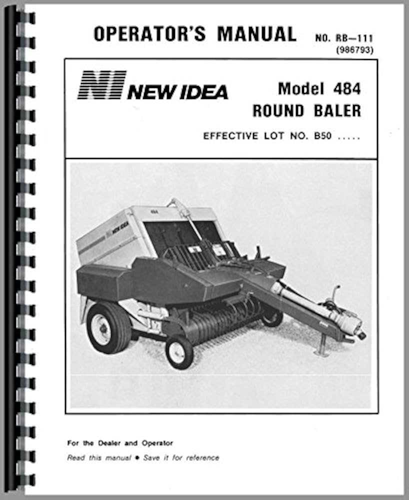
This agricultural equipment is designed for efficient and reliable fieldwork, simplifying the process of collecting and compacting materials into manageable forms. Its robust build ensures durability under tough conditions, making it a go-to choice for both small and large-scale operations.
Main Features
- High-efficiency pick-up system for quick material gathering.
- Durable frame and components for extended use.
- Adjustable settings for customizing the size and density of the output.
Operating Mechanism
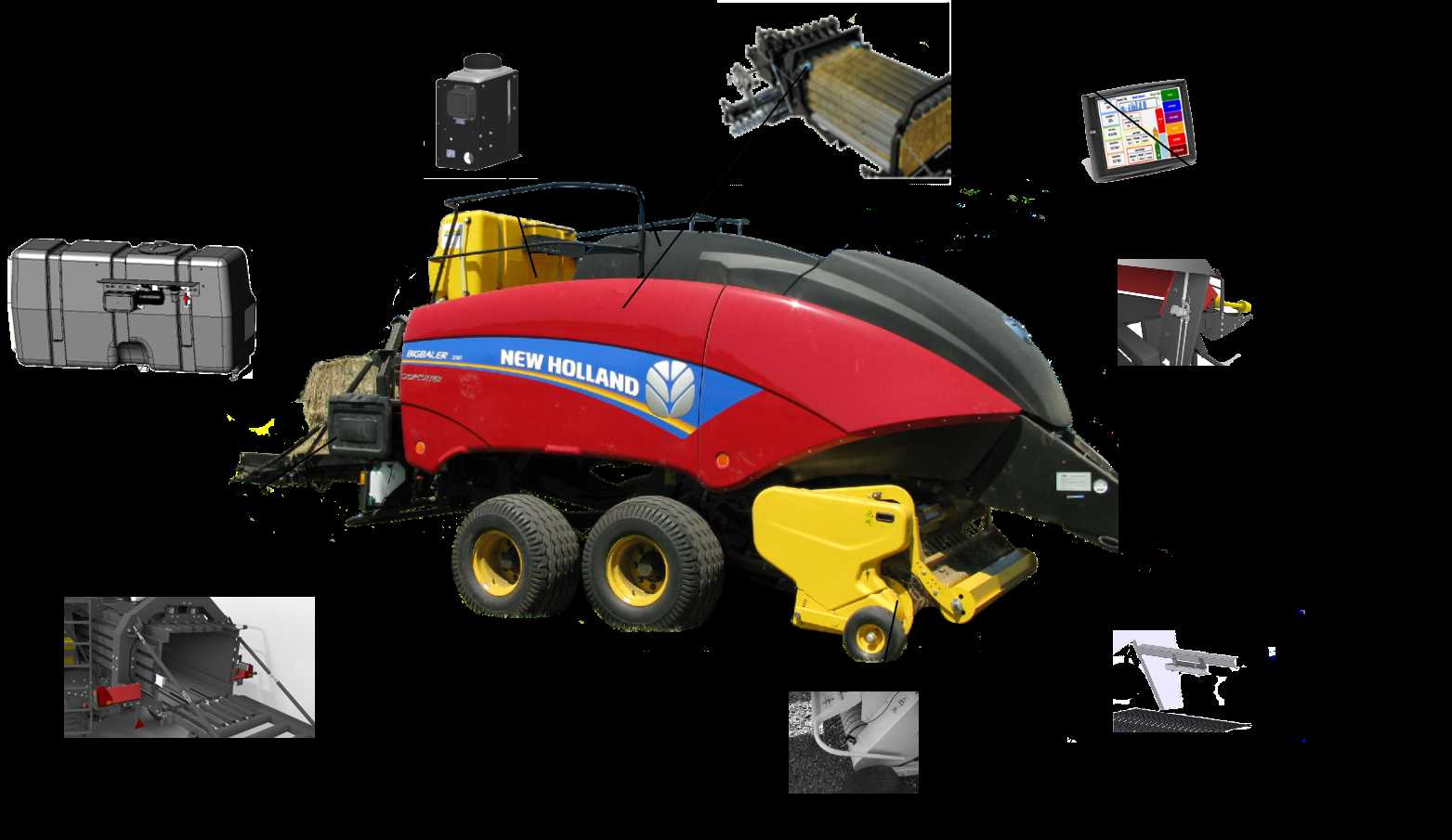
The machine operates using a series of rollers and belts that work in unison to compress and shape the material. With adjustable tension controls, it ensures consistent results while maintaining ease of operation for the user.
- Pick-up gathers material.
- Conveyor guides it into the compression chamber.
- Rollers apply pressure to form compact units.
- Once full, the formed product is tied or secured for transport.
Key Components of the Baler System
The efficiency and functionality of agricultural machinery depend on the precise operation of its various mechanical elements. Understanding the critical parts of the system allows for effective maintenance and repair, ensuring long-lasting performance and reliability.
- Main Frame: The foundation that supports all other components, designed to withstand high loads and provide stability during operation.
- PTO Shaft: A crucial link that transfers power from the tractor to the equipment, enabling it to function smoothly.
- Pickup Mechanism: Gathers the material from the ground and directs it into the processing chamber.
- Tying System: Secures the compressed material, ensuring it holds together after the cycle is complete.
- Hydraulic Components: Control various functions such as opening and closing of key sections, providing flexibility and automation in the process.
- Rollers and Belts: Work in unison to form and compress the material, shaping it into the final product.
Understanding the Drive Mechanism
The drive mechanism plays a crucial role in ensuring efficient operation by transferring power from the source to various working components. It coordinates multiple moving parts to maintain the timing and functionality of the entire system.
Main Components
The drive system consists of several interconnected parts that work together seamlessly to deliver smooth and reliable performance. Below are the key components involved in this process:
- Pulleys and Belts – Used to transmit motion and power between shafts and other moving elements.
- Chains and Sprockets – Provide mechanical advantage and synchronized movement for heavier loads.
- Gearbox – Ensures the appropriate distribution of torque and speed to different sections of the system.
Operational Workflow
The mechanism operates by converting rotational force into a series of precise actions that ensure continuous functionality. Below is a simplified breakdown:
- Power is generated and delivered to the primary pulley.
- Belts transfer the rotational energy to auxiliary components.
- Chains engage sprockets to synchronize m
Pickup System Parts and Functionality
The pickup mechanism plays a crucial role in the operation of agricultural machinery designed for gathering and processing materials from the field. This system ensures the efficient collection of hay or other crops, directing the gathered materials into the machine for further processing. Each component of the pickup unit works in harmony to optimize the flow of the harvest, contributing to smooth and consistent performance.
One of the essential elements in this system is the series of tines, which comb through the crop and lift it off the ground. These tines rotate on a reel, carefully picking up material without damaging it. Another important component is the cam track, guiding the movement of the tines to ensure precise lifting and dropping. Supporting rollers or wheels help maintain the correct height and positioning of the unit, adapting to uneven terrain for effective operation.
The drive mechanism, often powered through a belt or chain system, ensures the synchronization of all moving parts, from the tines to the rollers. This coordination is key to maintaining a steady pace of material collection, preventing blockages and enhancing overall productivity. The durability of these components, combined with regular maintenance, ensures reliable function across various working conditions.
Twine Wrap Mechanism and Parts
The twine wrapping system is essential for securing materials efficiently during the baling process. This mechanism ensures that the bale is tightly wrapped, preventing it from coming undone during transport or storage. Proper function relies on a series of components working in harmony to guide, tension, and release the twine at precise moments.
Twine Guides: These components direct the twine from the storage area to the wrapping point, ensuring it remains aligned throughout the process. They are typically adjustable to accommodate different sizes or types of twine.
Actuation System: This part initiates the wrapping cycle, engaging the mechanism that controls the twine release. It operates through mechanical or hydraulic means, depending on the equipment’s configuration.
Cutting Mechanism: After the twine has completed its cycle around the bale, the cutting mechanism is responsible for severing the twine at the appropriate moment, ensuring a clean and secure finish.
Each of these elements plays a crucial role in ensuring that the wrapping process is smooth and efficient, ultimately contributing to the reliability and performance of the equipment.
Hydraulic System Components
The hydraulic system is a crucial element in agricultural machinery, playing a significant role in the operation and efficiency of various tasks. This system utilizes pressurized fluid to transmit force and enable movement, ensuring smooth functionality across different mechanisms. Understanding its components is essential for maintenance and troubleshooting.
Key Components
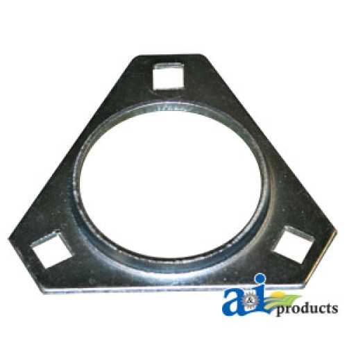
- Hydraulic Pump: Converts mechanical energy into hydraulic energy, generating pressure required for system operation.
- Hydraulic Cylinder: Responsible for converting hydraulic energy back into mechanical energy, facilitating movement of different parts.
- Control Valve: Regulates the flow and direction of hydraulic fluid, allowing precise control of the system’s operations.
- Hydraulic Reservoir: Stores hydraulic fluid, ensuring a constant supply and maintaining pressure within the system.
- Hoses and Fittings: Connect various components, allowing the fluid to flow between them while withstanding high pressures.
Maintenance Tips
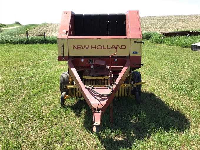
- Regularly check hydraulic fluid levels to ensure optimal performance.
- Inspect hoses and fittings for leaks or signs of wear.
- Clean filters to prevent contamination of hydraulic fluid.
- Monitor the hydraulic pump for unusual noises or performance issues.
- Test the control valve operation to ensure proper functionality.
Roller Assembly Breakdown
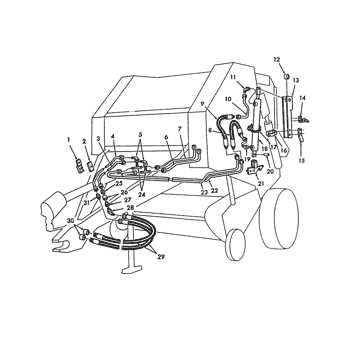
The roller assembly is a crucial component in the operation of agricultural machinery, ensuring the effective processing of materials. This section delves into the various elements that comprise the assembly, highlighting their functions and interconnections.
Typically, the roller assembly consists of several key elements, including the rollers themselves, bearings, and tensioning devices. Each roller plays a vital role in compressing and shaping the material as it passes through the machine. Bearings facilitate smooth rotation, reducing friction and wear, while tensioning devices ensure that the rollers maintain the appropriate pressure for optimal performance.
Understanding the structure and function of each component within the roller assembly is essential for maintenance and troubleshooting. Regular inspection and timely replacement of worn parts can significantly enhance the efficiency and longevity of the machinery.
Electric Wiring Diagram for the Baler
This section focuses on the essential electrical connections within the machinery, providing a clear understanding of how various components are integrated to ensure optimal functionality. Proper wiring is crucial for efficient operation and maintenance, allowing for smooth performance during usage.
Key Components and Their Functions
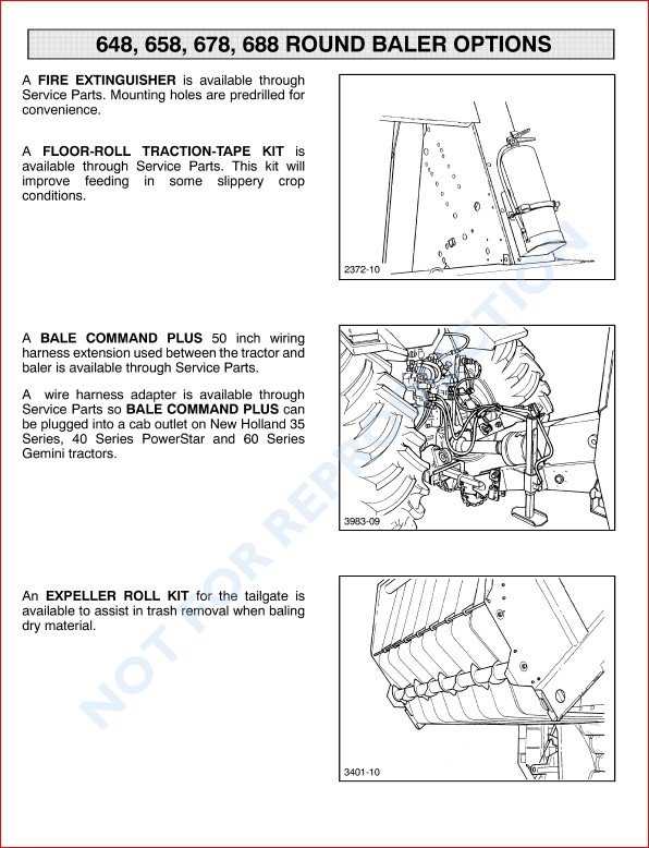
Understanding the main electrical components involved is vital. This includes the power supply, control switches, and safety devices. Each element plays a significant role in the overall system, contributing to the machine’s efficiency and safety. Proper identification and wiring of these components help prevent malfunctions and extend the lifespan of the equipment.
Wiring Configuration Tips
When working with electrical setups, it is important to follow the correct configuration to avoid potential hazards. Utilize color-coded wires for easier identification, and ensure that all connections are secure and properly insulated. Regularly inspecting the wiring for wear or damage can significantly reduce the risk of electrical failures during operation.
Maintenance Points and Critical Parts
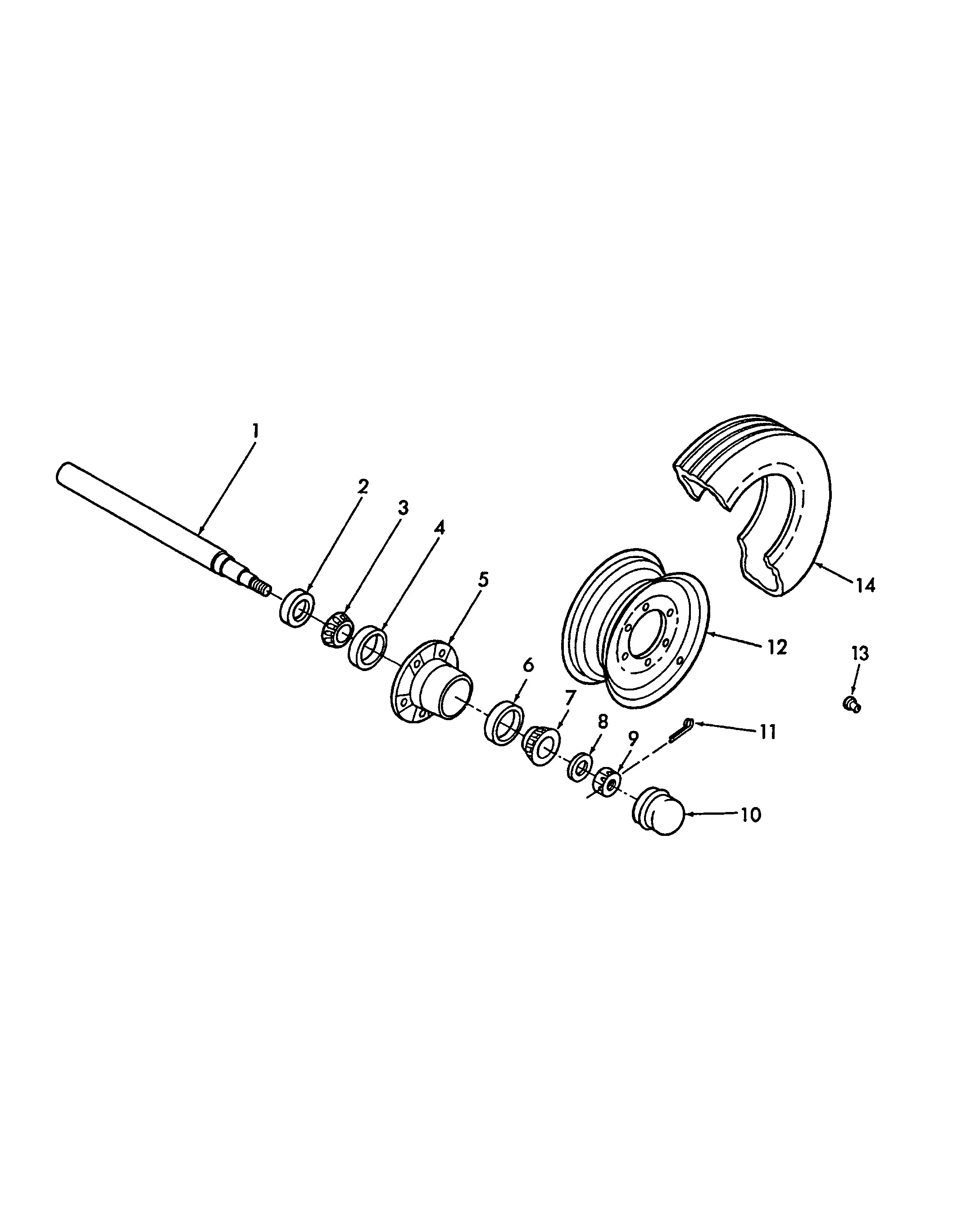
Regular upkeep of agricultural machinery is vital for ensuring optimal performance and longevity. This section highlights essential maintenance aspects and key components that require attention to keep your equipment functioning efficiently.
Lubrication: Proper lubrication of moving parts is crucial. Regularly check and apply grease to bearings, chains, and pivot points to minimize wear and tear, reducing the risk of breakdowns.
Inspection: Conduct routine inspections of critical elements such as the cutting blades, belts, and rollers. Look for signs of damage or excessive wear that could hinder performance or lead to failure during operation.
Adjustment: Ensure that settings for tension and alignment are appropriately calibrated. Misalignment can cause uneven wear and increased strain on components, leading to premature failure.
Cleaning: Keep the machine clean by removing debris and residue that can accumulate during use. A clean environment helps prevent rust and corrosion, extending the life of vital components.
Storage: When not in use, store the machinery in a dry, sheltered area to protect it from the elements. Proper storage conditions help maintain the integrity of sensitive parts and reduce the risk of damage.
Baler Chamber Parts and Design
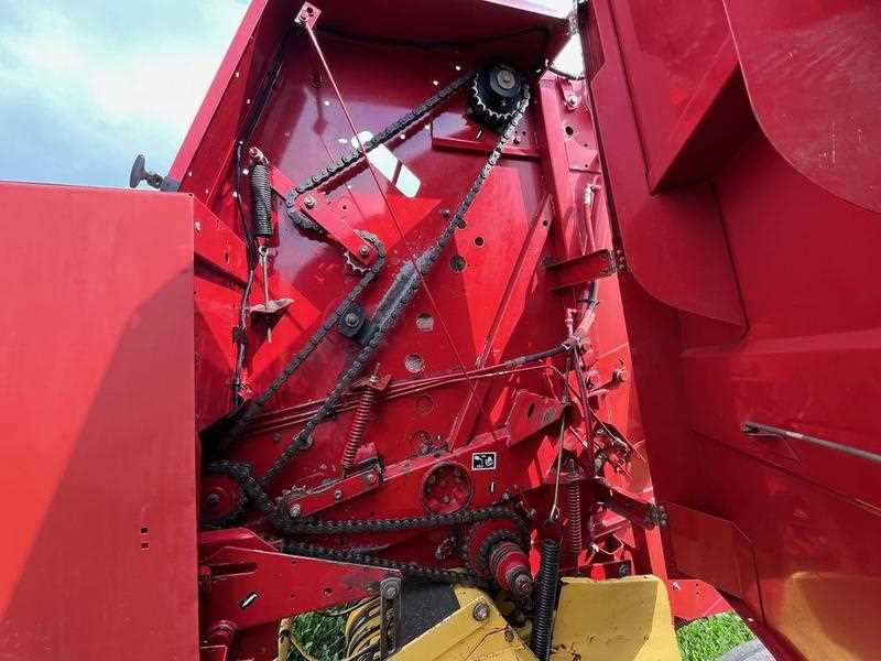
The design of the chamber within a forage compression system plays a crucial role in ensuring efficiency and optimal performance. This section explores the various components that contribute to the effective operation of this critical mechanism, emphasizing their functions and interactions.
Understanding the assembly of the chamber is essential for anyone involved in maintenance or troubleshooting. The key components typically include:
Component Description Side Plates These structural elements provide stability and support, helping to maintain the shape of the chamber during operation. Feed Rollers These components guide the material into the chamber, ensuring a consistent flow for efficient compression. Compression Floor This base supports the material being compacted, facilitating effective pressure distribution across the load. Pressure Cylinders These hydraulic elements apply the necessary force to compress the material, crucial for achieving the desired density. Door Mechanism This component allows for easy access during maintenance and enables the release of the finished product. Each of these elements is integral to the overall functionality of the system, working in harmony to achieve optimal results in material compression and efficiency.
Troubleshooting Common Issues with Parts
When operating agricultural equipment, encountering issues with components is a frequent challenge that can affect overall efficiency and productivity. Identifying and addressing these problems promptly can prevent costly downtime and extend the life of the machinery. Below are some common concerns and practical solutions to help you maintain optimal functionality.
- Worn Components: Regular wear and tear can lead to decreased performance.
- Check for Friction: Inspect moving parts for excessive friction which may cause overheating and damage.
- Loose Connections: Ensure all connections are tight and secure to avoid operational interruptions.
Each of these issues may manifest in various ways, such as unusual noises, decreased output, or mechanical failure. To effectively troubleshoot, consider the following steps:
- Perform a visual inspection of the machine and its components.
- Refer to the maintenance manual for specific guidelines related to the model.
- Replace any damaged or worn components with quality replacements.
By following these recommendations and being proactive in your maintenance practices, you can effectively manage common challenges associated with equipment components.
How to Replace Worn Components

Maintaining optimal performance of agricultural machinery involves timely replacement of degraded elements. Understanding the procedure for substituting these components can significantly enhance the efficiency and longevity of your equipment. This section outlines the essential steps to effectively replace worn parts, ensuring your machinery operates smoothly.
Identifying Worn Components
Before beginning the replacement process, it is crucial to accurately identify the components that require attention. Common indicators of wear include unusual noises, decreased performance, or visible damage. Regular inspections can help in pinpointing these issues early on.
Replacement Procedure
Follow these steps to ensure a successful component replacement:
Step Description 1 Turn off the machine and disconnect it from the power source to ensure safety. 2 Remove any necessary covers or shields to access the worn components. 3 Carefully detach the worn components, taking note of their arrangement for reassembly. 4 Install the new components, ensuring they are securely fastened and aligned correctly. 5 Replace any covers or shields, and reconnect the power source. 6 Test the machinery to confirm that the new components are functioning as intended. Following these steps will help maintain the reliability of your equipment, allowing it to perform at its best for years to come.