Ignition System Parts
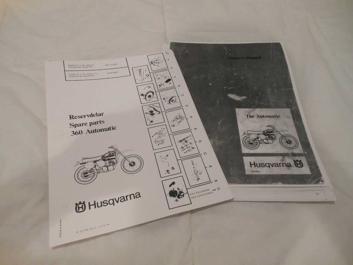
The ignition system plays a crucial role in starting and maintaining the operation of a small engine. This system includes several interconnected components designed to generate and control the spark necessary for combustion. Understanding how these elements work together ensures proper function and helps diagnose issues more efficiently.
Key elements of the ignition setup include the spark module, which produces the electrical charge, and the coil, responsible for amplifying this charge. Additionally, the flywheel works in conjunction with magnets to create the initial voltage, ensuring smooth engine ignition and continuous operation. Each part is essential for reliable performance.
Air Filter and Carburetor Configuration
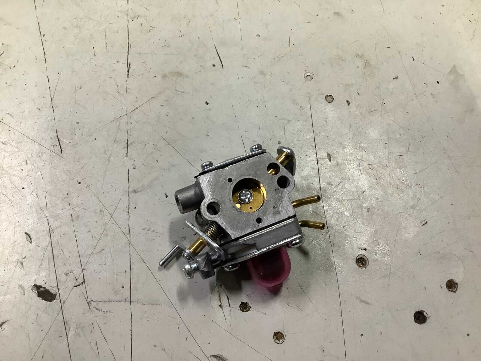
The effectiveness of small engine performance relies significantly on the configuration of the air filtration system and the fuel mixing apparatus. These components play a crucial role in ensuring that the engine receives the correct mixture of air and fuel for optimal combustion. Proper maintenance and understanding of their arrangement can lead to improved efficiency and longevity of the equipment.
Air Filter Maintenance
The air filter is essential for preventing dirt and debris from entering the engine. A clean filter ensures an unobstructed airflow, which is vital for maintaining the correct fuel-to-air ratio. Regular inspection and cleaning of the filter are recommended to keep the engine running smoothly. In cases where the filter is damaged or excessively dirty, replacement is necessary to restore performance.
Carburetor Adjustments
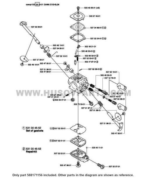
The carburetor is responsible for mixing air and fuel in the appropriate ratio. Its configuration can greatly affect the engine’s responsiveness and overall performance. Periodic adjustments may be required to ensure that the carburetor operates efficiently. This includes checking the settings for both idle and high-speed operations, which can be crucial for various tasks and environments.
Conclusion
Maintaining the air filter and adjusting the carburetor are key steps in preserving the functionality of small engines. By focusing on these components, users can enhance performance, reduce emissions, and prolong the life of their equipment.
Clutch and Drive Mechanism
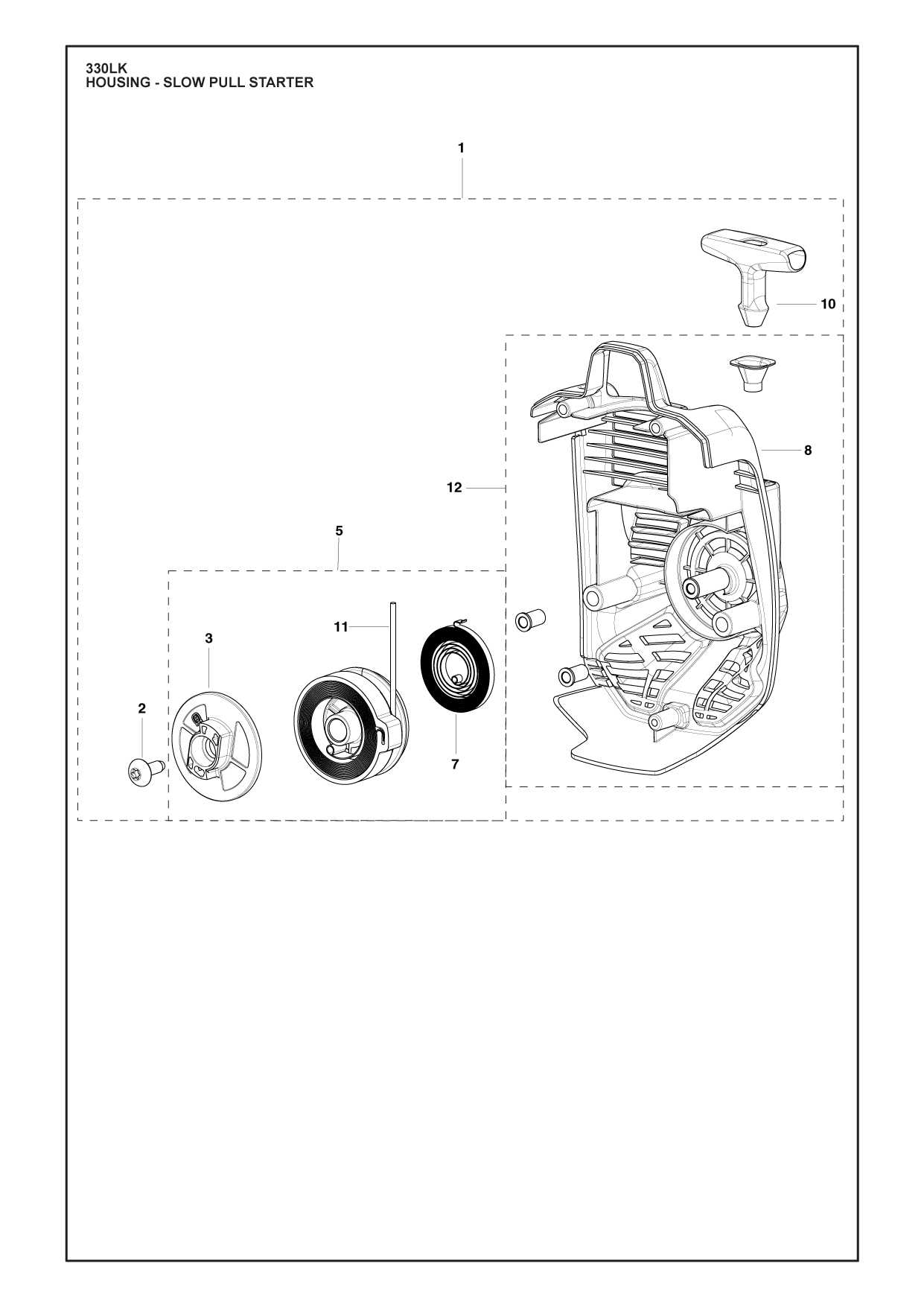
The clutch and drive mechanism is a vital component in the operation of various power equipment. This system allows for the controlled transfer of energy from the engine to the working tools, ensuring optimal performance and efficiency. Understanding how this mechanism functions can enhance maintenance practices and improve overall reliability.
Functionality of the Clutch
The primary role of the clutch is to engage and disengage the engine’s power to the drive system. When engaged, the clutch transmits torque, enabling the device to operate. Conversely, disengaging the clutch allows the operator to stop the tool without shutting down the engine. This feature is crucial for tasks that require precision and control, providing the flexibility needed in various applications.
Drive Mechanism Overview
The drive mechanism works in conjunction with the clutch to convert the rotational force generated by the engine into usable motion. It typically consists of gears, belts, or chains that facilitate this transfer. Proper maintenance of these components is essential, as wear and tear can lead to decreased efficiency and potential failures. Regular inspection and timely replacements can significantly extend the lifespan of the entire system.
Exhaust System Diagram
The exhaust system is a crucial component that manages the expulsion of combustion gases from the engine, ensuring optimal performance and compliance with environmental regulations. Understanding its layout and functionality can aid in effective maintenance and troubleshooting, contributing to the longevity and efficiency of the equipment.
Components Overview
This section provides insight into the key elements that comprise the exhaust assembly. Essential parts include the muffler, pipes, and connectors, each playing a vital role in directing and silencing the exhaust flow. Recognizing these components helps in identifying potential issues that may arise during operation.
Functionality and Maintenance
The proper functioning of the exhaust assembly is critical for engine efficiency. Regular inspections and maintenance of the system can prevent blockages and leaks, which can lead to performance degradation. Understanding the arrangement of the components allows for better diagnostics and timely interventions.
Handlebar and Control Unit

The handlebar and control unit are essential components that enhance the operator’s experience and ensure effective handling of the equipment. These elements are designed to provide a comfortable grip and intuitive access to various functions, allowing for efficient operation in diverse working conditions.
Construction and Ergonomics
The handlebar is typically constructed from durable materials that can withstand outdoor conditions while providing a comfortable grip. The ergonomic design minimizes fatigue during prolonged use, enabling the operator to maintain control and precision.
Functionality and Controls
The control unit integrated into the handlebar houses various switches and levers, enabling the user to easily manage different operations. This arrangement promotes seamless interaction with the machinery, ensuring that adjustments can be made swiftly without compromising safety or performance.
Maintenance and Safety Considerations
Regular inspection of the handlebar and control unit is crucial for maintaining optimal performance. Any signs of wear or damage should be addressed immediately to prevent operational issues and ensure the safety of the user. Proper maintenance will prolong the lifespan of these components and enhance overall efficiency.
Blade and Cutting Equipment Structure
The cutting apparatus of outdoor power tools consists of various components designed to optimize performance and enhance efficiency. Understanding the configuration of these elements is essential for achieving effective operation and maintenance.
Key Components of the Cutting System
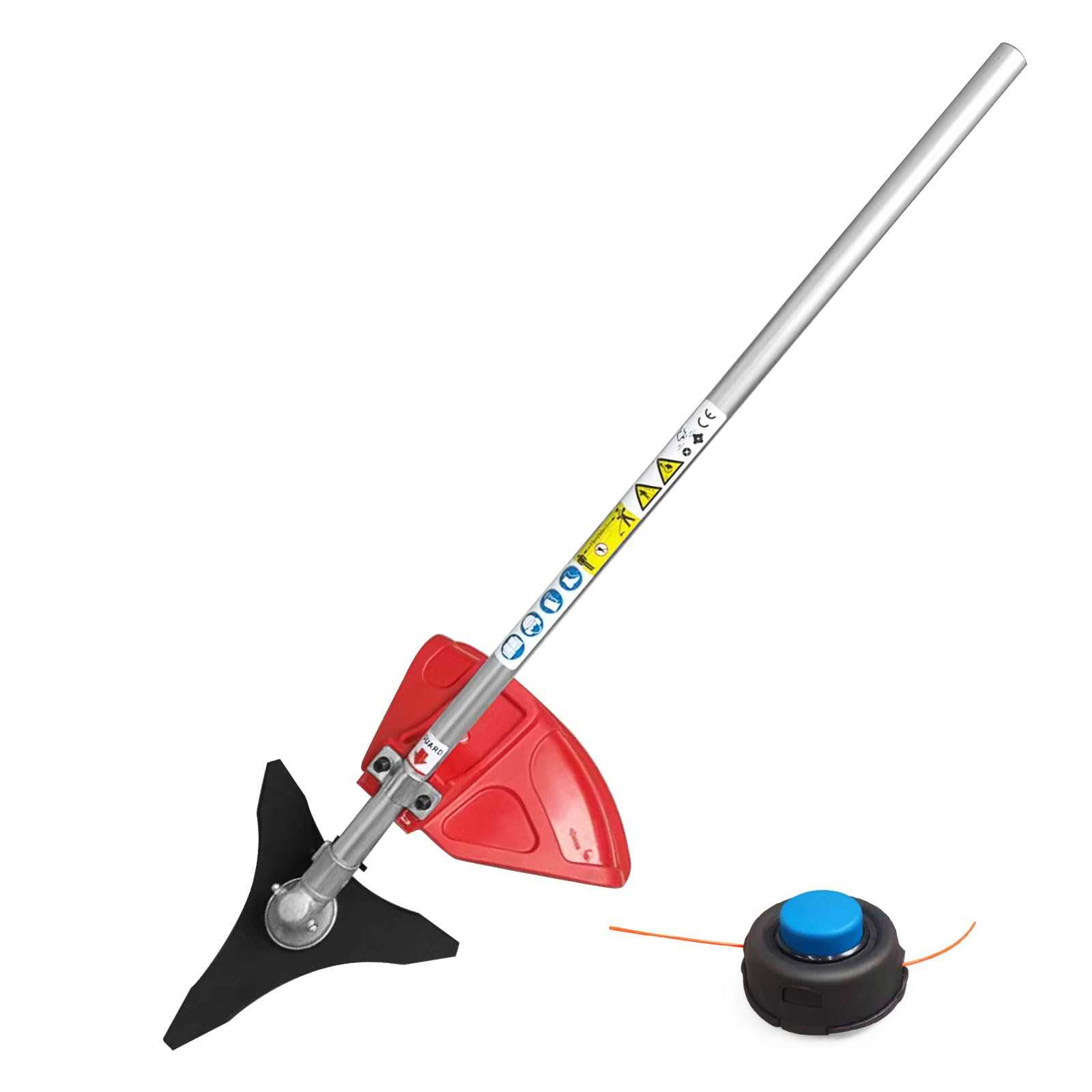
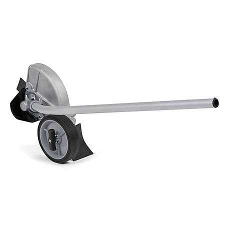
At the heart of the cutting system lies the blade, crafted from durable materials to withstand wear and tear. The hub connects the blade to the engine, ensuring seamless power transfer. Additionally, the guard serves as a protective element, shielding the operator from debris while maintaining safety during operation.
Cutting Mechanism Functionality
The cutting mechanism operates through a combination of rotational force and precise engineering. The blade’s design influences the quality of the cut, while the interaction between the blade and other components determines the overall efficiency of the tool. Proper maintenance of these parts is crucial for optimal performance and longevity.
Protective Covers and Guards
In any machinery or equipment, protective components play a crucial role in ensuring safety and enhancing performance. These essential elements not only shield users from potential hazards but also help maintain the integrity of the machinery over time.
There are various types of protective covers and guards designed to meet specific needs:
- Blade Guards: These are designed to prevent accidental contact with cutting edges, providing a safety barrier during operation.
- Debris Shields: These components help keep loose materials from interfering with moving parts, ensuring a clean and safe working environment.
- Weather Covers: Protective coverings that shield machinery from harsh environmental conditions, prolonging lifespan and functionality.
- Control Panel Guards: These protect sensitive controls from damage and accidental activation, ensuring safe operation.
Regular maintenance and inspection of these protective features are essential to ensure they function correctly. Damaged or worn components should be replaced promptly to maintain the safety and efficiency of the equipment.
Maintenance and Replacement Parts Guide
Effective upkeep of your outdoor equipment is essential for optimal performance and longevity. Regular maintenance not only ensures reliable operation but also helps prevent potential issues that could arise from wear and tear over time.
In this section, we will explore various components that may require periodic inspection or replacement. Understanding these elements will aid in maintaining functionality and efficiency. It’s important to refer to your user manual for specific details regarding your equipment’s unique requirements.
Routine Inspection: Regularly check the condition of the main components, including the engine, fuel system, and cutting mechanisms. Look for signs of damage or wear, and address any issues promptly to avoid further complications.
Replacement Recommendations: Identify parts that may need to be changed due to degradation, such as filters, spark plugs, and blades. Utilizing high-quality replacements will ensure the best performance and reliability.
Tools and Accessories: Equip yourself with the necessary tools for maintenance tasks, including wrenches, screwdrivers, and safety gear. Having the right tools on hand simplifies the maintenance process and enhances safety.
By adhering to a consistent maintenance routine and replacing worn components, you can maximize the efficiency and lifespan of your outdoor machinery.
