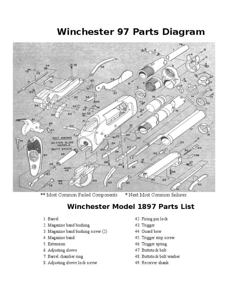
The internal structure of classic firearms is a fascinating combination of precision and durability. Understanding how each element works together to ensure proper functioning is essential for those interested in maintaining or restoring such devices. These intricate designs, though complex, are built with a balance of simplicity and purpose.
Each individual element, from the smallest pin to the larger operating mechanisms, plays a vital role in the overall performance. By examining these mechanisms closely, we can appreciate the engineering prowess behind their creation, making it easier to troubleshoot, repair, or enhance their operation.
In this exploration, we’ll focus on key elements that form the operational heart of these firearms. Breaking down their function and assembly can offer valuable insights for enthusiasts and technicians alike, whether you’re aiming to maintain optimal performance or restore an older piece to working condition.
Overview of Winchester 120 Components
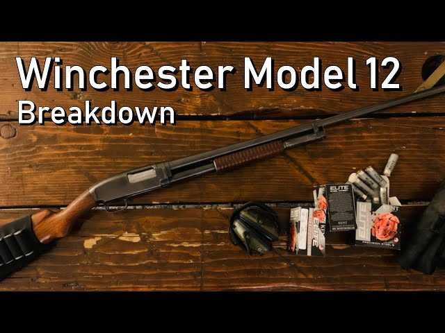
The internal structure of this firearm is crafted with precision, featuring several interconnected elements that ensure reliable performance. Each piece has its unique role in maintaining the efficiency and smooth operation of the overall system, offering durability and consistent accuracy.
Main Structural Elements
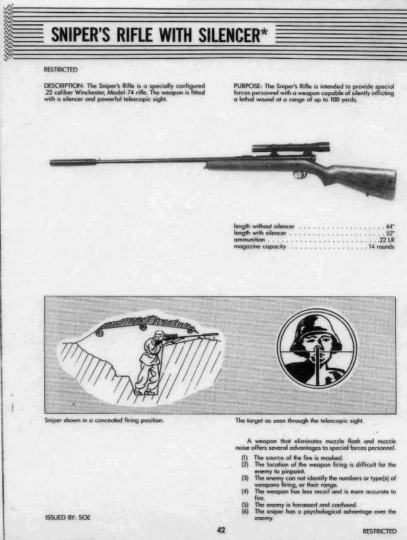
The core framework is built from sturdy materials, providing a solid foundation. Key areas include the barrel, which serves as the guiding path for the ammunition, and the stock, designed for ergonomic handling and support. The assembly includes moving parts responsible for loading, firing, and ejecting rounds, each performing its function seamlessly.
Additional Mechanisms
Smaller components, such as the trigger mechanism and safety features, add essential control. The trigger group ensures precise firing, while safety locks provide critical protection against accidental discharge. These mechanisms work together to create a balance between power and control, contributing to the firearm’s overall reliability.
Barrel and Receiver Assembly Breakdown
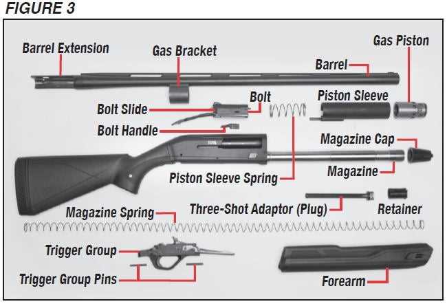
The connection between the barrel and receiver forms a critical component in the overall function of a firearm. Understanding the various elements involved in their assembly helps to ensure proper alignment, optimal performance, and easy maintenance. Each part is designed to work in unison, providing structural integrity and facilitating smooth operation during use.
| Component | Description |
|---|---|
| Barrel | This long, cylindrical part guides the projectile and ensures accurate discharge. |
| Receiver | The housing that contains the firing mechanism, connecting all other parts. |
| Locking Bolt | Secures the barrel to the receiver, ensuring stability during firing. |
| Extractor | Facilitates the removal of spent casings after firing. |
| Component | Description |
|---|---|
| Magazine Tube | Holds the ammunition and aligns cartridges with the action. |
| Spring | Provides the necessary pressure to feed cartridges into the chamber. |
Firing Pin and Bolt Configuration
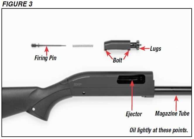
This section focuses on the intricate relationship between the firing mechanism and the bolt assembly. Understanding how these components interact is crucial for ensuring the reliable operation of the firearm.
| Component | Description |
|---|---|
| Firing Pin | A slender rod that strikes the primer of a cartridge, initiating the firing sequence. |
| Bolt | The component that houses the firing pin and is responsible for chambering rounds and locking the breech. |
| Spring Mechanism | A spring that provides the necessary tension to propel the firing pin forward when triggered. |
| Locking Lugs | Features on the bolt that engage with the receiver to secure the action during firing. |
Detailed View of Ejector System
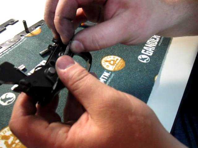
The ejector mechanism plays a crucial role in the functioning of firearms, ensuring the reliable expulsion of spent cartridges after each shot. This system’s efficiency directly impacts the overall performance and reliability of the firearm, making its design and components vital for enthusiasts and professionals alike.
Components of the Ejector Mechanism
At the core of the ejector system are several key elements that work in harmony to facilitate the ejection process. These include the ejector itself, a spring, and various pins and levers. Each component is designed to endure significant stress during operation, and their precise alignment is essential for optimal performance.
Functionality and Operation
Upon firing, the ejector engages with the cartridge case, utilizing a spring-loaded mechanism to push the spent shell outward. This action is typically timed with the cycling of the action, ensuring that the next round can be chambered without delay. A well-tuned ejector system enhances the shooting experience by minimizing jams and malfunctions.
Disassembly of the Action Lock Lever

Understanding the process of removing the action lock lever is essential for proper maintenance and troubleshooting. This component plays a crucial role in the overall functionality, and careful disassembly ensures that it can be serviced without causing damage.
Begin by ensuring the firearm is unloaded and safe to handle. Use appropriate tools to remove any retaining pins or screws that secure the lever in place. Take note of the orientation and positioning of each part as you proceed, as this will aid in reassembly. Gently lift the lever from its housing, being cautious of any springs or small components that may be under tension. Keep these elements organized to prevent loss and facilitate easier reinstallation.
Once the action lock lever is free, inspect it for wear or damage. Regular checks can help maintain optimal performance and safety. If necessary, clean the area around the lever before proceeding with reassembly or further servicing.
Exploring the Sear and Hammer Interaction
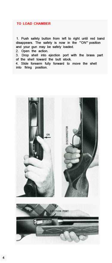
The interaction between the sear and the hammer is a critical aspect of firearm functionality. Understanding how these components work together is essential for proper maintenance and troubleshooting. This section delves into their relationship and the role each plays in the firing mechanism.
The sear is designed to hold the hammer in a cocked position until the trigger is pulled. Here’s how this interaction unfolds:
- The hammer is held back by the sear, preventing accidental discharge.
- When the trigger is engaged, it releases the sear, allowing the hammer to fall.
- The hammer strikes the firing pin, initiating the ignition of the cartridge.
Several factors can affect this interaction:
- Wear and tear on the sear can lead to misfires or premature firing.
- Proper lubrication is essential for smooth operation.
- Regular inspections can help identify potential issues before they become serious.
Understanding these dynamics is vital for enthusiasts and professionals alike, ensuring safe and reliable operation of the firearm.
Recoil Pad and Buttplate Components
The recoil cushioning system plays a crucial role in enhancing shooting comfort and stability. It comprises essential elements that work together to mitigate the impact felt during firing, thereby improving overall control and accuracy.
Recoil Pad: This component is designed to absorb shock and reduce the felt recoil when the firearm is discharged. Made from durable materials, it provides a non-slip surface that ensures a secure shoulder placement during use.
Buttplate: Typically crafted from a sturdy material, the buttplate serves as the rear end of the firearm stock. It not only contributes to the aesthetics but also reinforces the overall structure. Its design can influence the balance and weight distribution, affecting the handling characteristics.
Understanding the functionality and significance of these components is essential for maintenance and customization, allowing users to enhance their shooting experience effectively.
Fore-end Cap and Slide Action Mechanism
The fore-end cap and slide action system play a crucial role in the functionality and reliability of a shotgun. This mechanism allows for smooth operation during cycling, contributing to the overall performance of the firearm.
Understanding the components involved in this assembly can aid in maintenance and troubleshooting. Below is a detailed overview of the main elements associated with the fore-end cap and slide action mechanism.
| Component | Description |
|---|---|
| Fore-end Cap | The cap secures the fore-end to the action, providing stability and protection to the internal parts. |
| Slide Tube | Connects the fore-end to the receiver, allowing for the smooth forward and backward movement necessary for operation. |
| Action Bars | These bars facilitate the sliding mechanism, ensuring that the fore-end moves efficiently in coordination with the cycling of the firearm. |
| Fore-end Assembly | Houses the slide action components and aids in guiding the movement during firing. |
Proper Maintenance of Small Internal Parts
Ensuring the longevity and optimal performance of intricate components requires regular attention and care. These essential elements often play a crucial role in the overall functionality of the device. Adopting a systematic approach to maintenance can significantly reduce wear and tear, enhancing reliability over time.
Regular Cleaning Procedures
Routine cleaning is vital to prevent the accumulation of dirt and debris that can interfere with the operation of internal components. Use a soft brush or cloth to gently remove dust, and consider applying a suitable cleaning solution when necessary. Avoid harsh chemicals that may damage sensitive materials.
Lubrication and Protection
Applying appropriate lubricants to moving parts can significantly enhance their efficiency and reduce friction. Ensure that the lubricant used is compatible with the materials involved. Additionally, protecting these components from moisture and extreme temperatures is essential for maintaining their integrity.
| Maintenance Task | Recommended Frequency |
|---|---|
| Cleaning | Every 3 months |
| Lubrication | Every 6 months |
| Inspection for Wear | Annually |

