In the world of heavy machinery, understanding the intricate structure of various elements is crucial for ensuring smooth operation and timely maintenance. Efficient management of mechanical components can make a significant difference in performance, helping to prevent issues before they arise. By gaining insight into the layout of essential components, operators and technicians can enhance both the functionality and longevity of their equipment.
A detailed visual guide of mechanical configurations can provide a clearer understanding of how different elements work together. This type of illustration helps users to locate specific elements more easily, facilitating troubleshooting and replacement processes. With this knowledge in hand, both routine check-ups and unexpected repairs become far more manageable.
For those who regularly engage in maintenance or repairs, having access to an accurate visual representation is an invaluable tool. Such resources allow for a more organized approach when working on machinery, ensuring that each task is performed with precision. This exploration of mechanical layouts will support individuals in identifying, replacing, or upgrading various elements efficiently and effectively.
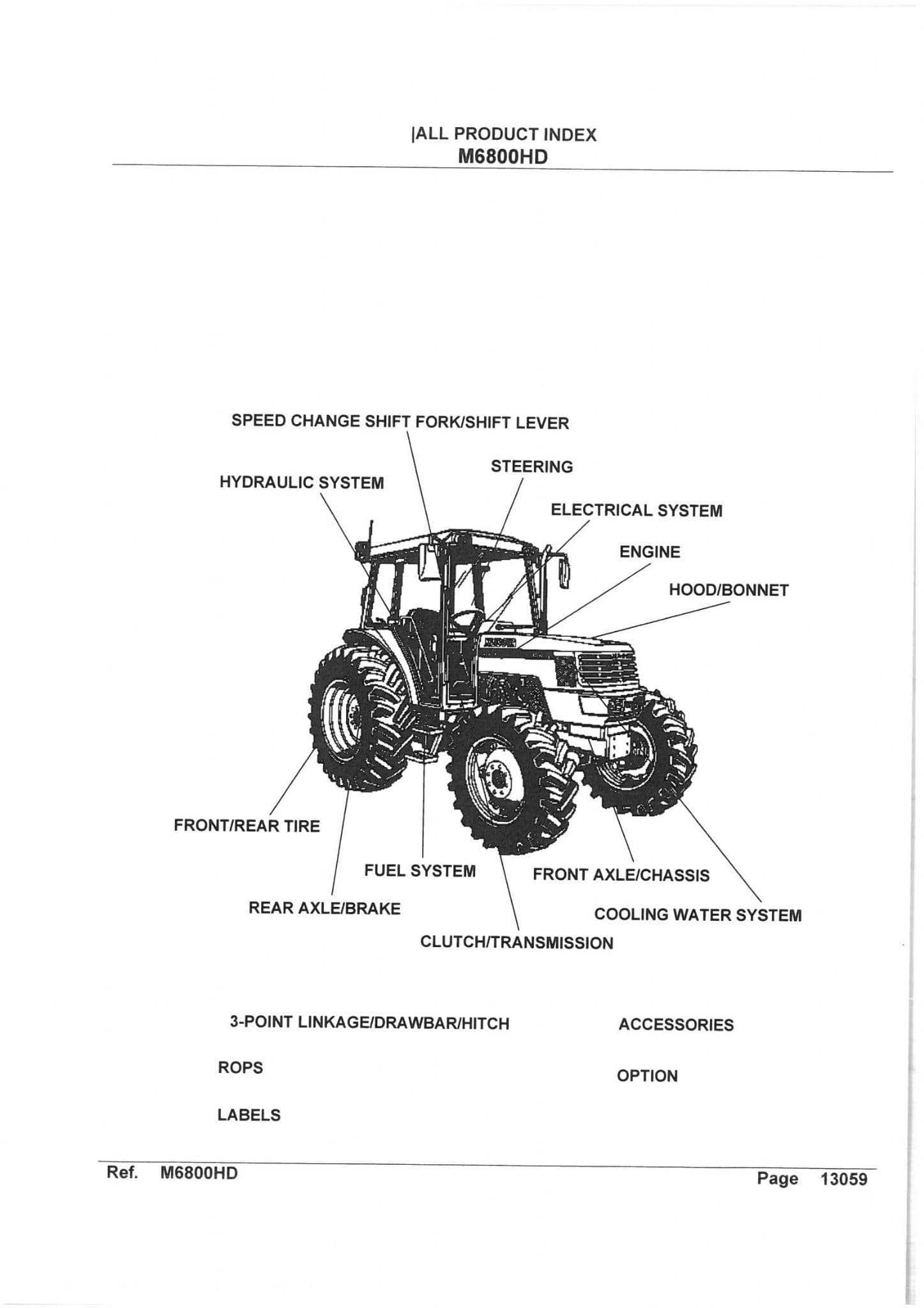
Kubota M6800 Component Layout Overview
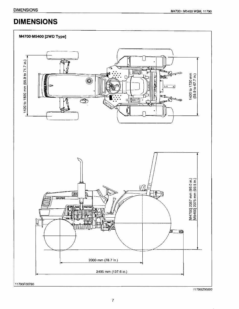
The machinery’s layout is crucial for understanding the relationship between its various systems. Each section is designed to provide optimal performance while allowing for easy access and maintenance. The spatial arrangement ensures efficient operation, with key elements strategically positioned for functionality and convenience.
| Component Group | Location | Primary Function | |||||||||||||||||||||||||||||||||||||
|---|---|---|---|---|---|---|---|---|---|---|---|---|---|---|---|---|---|---|---|---|---|---|---|---|---|---|---|---|---|---|---|---|---|---|---|---|---|---|---|
| Engine Assembly | Front Section | Provides mechanical power for operation | |||||||||||||||||||||||||||||||||||||
| Hydraulic System | Mid-section | Controls fluid dynamics for various attachments | |||||||||||||||||||||||||||||||||||||
| Transmission Unit | Lower Central Area | Enables speed adjustment and torque distribution | |||||||||||||||||||||||||||||||||||||
| Operator’s Platform | Upper Center | Offers control interface and seating for the operator | |||||||||||||||||||||||||||||||||||||
| Cooling System | Front Adjacent to Engine | Maintains optimal engine temperature during operation |
| Component | Description | Function |
|---|---|---|
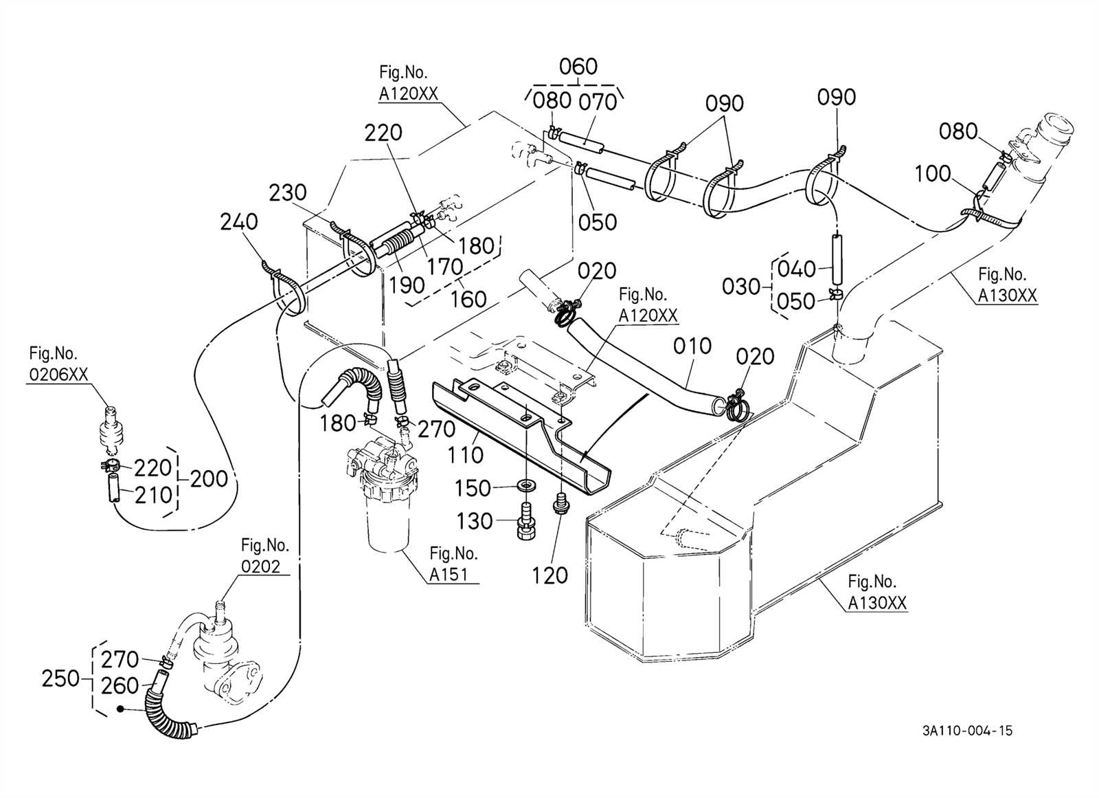
| Fuel Pump | Transfers fuel from the tank to the engine | Ensures a steady fuel supply to the system |
| Fuel Injectors | Sprays fuel into the combustion chamber | Delivers fuel in a controlled manner for combustion |
| Fuel Lines | Conveys fuel from the pump to the injectors | Ensures proper fuel flow throughout the system |
Maintaining Optimal Fuel Flow

For the system to function optimally, regular checks of fuel lines and filters are necessary to avoid blockages or wear. A clogged filter or damaged line can hinder fuel delivery, causing performance issues. Routine inspections can help identify potential problems before they escalate.
Cooling System Layout and Components

The cooling arrangement of an engine plays a crucial role in maintaining optimal temperature levels during operation. This system prevents overheating by dissipating excess heat generated by the engine, ensuring smooth performance and longevity. Various elements within the system work together to regulate and manage the heat exchange process efficiently.
The primary components include a radiator, thermostat, coolant reservoir, and associated hoses. Each of these parts is strategically placed to promote maximum cooling efficiency. The radiator is responsible for expelling heat from the coolant, which circulates through the engine block. The thermostat controls the flow of coolant based on temperature readings, ensuring that the engine operates within a safe temperature range. Coolant hoses connect all components, allowing the coolant to flow seamlessly throughout the system.
Additionally, the water pump facilitates the movement of coolant, circulating it through the engine and radiator. Fans, often mounted to the radiator, help enhance airflow, aiding in the cooling process, particularly during low-speed operation or idle conditions. Together, these components create a well-coordinated system that protects the engine from thermal damage and enhances its efficiency.
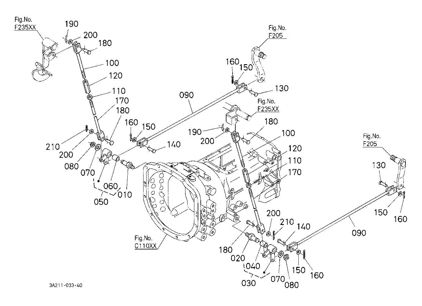
Brake and Clutch Mechanism Breakdown

The braking and clutch systems play a pivotal role in the smooth operation of machinery, ensuring both safety and efficiency. Understanding their structure and function is essential for proper maintenance and timely repairs. This section will explore the core components, their functions, and how they interact to maintain performance under various conditions.
Brake System Overview
The braking system is responsible for slowing down and stopping the machine by converting kinetic energy into heat. Key components include:
- Brake Pads: These are the friction elements that make contact with the brake discs to generate resistance.
- Brake Discs: Rotating components that interact with the pads to slow down or stop movement.
- Master Cylinder: A vital component that houses the hydraulic fluid and applies pressure to the braking system.
Clutch Mechanism Components
The clutch system ensures smooth engagement and disengagement of the engine from the transmission, allowing for efficient gear shifts. Key elements include:
- Clutch Pedal: This is the primary interface used to disengage the clutch system, giving the operator control over power transfer.
- Clutch Plates: These discs engage and disengage the transmission from the engine, allowing for smooth operation.
- Flywheel: A rotating part that helps in smooth engagement and stores kinetic energy to assist in starting the machine.
Front and Rear Axle Configuration
The overall structure of the vehicle’s drive system plays a crucial role in its stability, maneuverability, and load distribution. The arrangement of both the front and rear axles ensures effective power transfer, providing support for various operational tasks and terrain navigation. Proper understanding of these components can enhance maintenance and functionality, allowing for smoother operation under different conditions.
Front Axle Mechanics
The front axle is integral to the steering and traction system. It supports the front wheels, allowing them to rotate and absorb shock while maintaining control over directional movement. This axle configuration is designed to handle the forces generated during steering, providing stability during turns and ensuring a safe drive across diverse terrains.
Rear Axle Design
The rear axle is responsible for transferring the driving force to the rear wheels, making it a vital component for propelling the vehicle. It carries the weight of the vehicle’s rear section, balancing the load and ensuring efficient energy distribution. The rear axle’s design is optimized for durability, particularly in load-bearing applications.
| Component | Function | Key Features |
|---|---|---|
| Front Axle | Steering and shock absorption | Supports steering, absorbs shocks, provides stability |
| Rear Axle | Power transfer and weight support | Transmits driving force, carries weight, durable design |
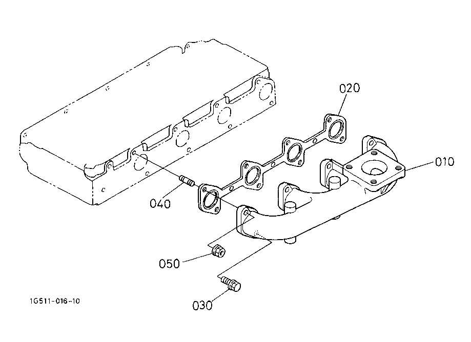
Exhaust and Emission Control Path
The system responsible for managing gases generated during combustion plays a crucial role in ensuring optimal engine performance and compliance with environmental standards. This pathway is designed to effectively reduce harmful emissions while maintaining power output and fuel efficiency.
Key Components of the Emission Pathway
- Exhaust manifold: Collects exhaust gases from the engine cylinders and directs them toward the exhaust system.
- Turbocharger: Enhances engine efficiency by increasing the amount of air entering the engine, improving combustion and reducing emissions.
- Diesel Particulate Filter (DPF): Captures and stores soot and particulate matter from the exhaust before they are released into the atmosphere.
- Catalytic converter: Uses chemical reactions to reduce harmful gases such as nitrogen oxides, carbon monoxide, and hydrocarbons into less harmful substances.
- Exhaust gas recirculation (EGR) valve: Recirculates a portion of the exhaust gases back into the intake air, helping to lower combustion temperatures and reduce nitrogen oxide emissions.
Efficiency and Maintenance Considerations
For the system to function efficiently, regular inspection and maintenance are required. Clogged filters or malfunctioning components can lead to increased emissions and decreased engine performance. Timely servicing ensures both environmental compliance and optimal engine longevity.
Steering Mechanism Parts and Connections
The steering system is a crucial component for controlling the direction of any vehicle. It includes a variety of interconnected elements that work together to ensure precise movement and handling. These components must be arranged in a way that provides both stability and responsiveness when navigating different terrains.
| Component | Description |
|---|---|
| Steering Wheel | The primary interface for the driver, enabling control over the direction of the machine. |
| Steering Column | A shaft that transmits the driver’s input from the steering wheel to the mechanism that controls the front wheels. |
| Linkage | A series of rods and joints that connect the steering wheel to the front wheels, allowing for directional movement. |
| Steering Box | A mechanism that converts the rotational motion from the steering wheel into the linear motion needed to turn the wheels. |
| Ball Joints | Flexible joints that allow for the movement of the linkage and steering components while maintaining stability and control. |
| Hydraulic Cylinder | A device that uses fluid pressure to assist in the ease of steering, reducing effort for the operator. |
| Front Axle | The component that supports the front wheels and connects them to the rest of the steering mechanism, allowing for controlled movement. |
Each element plays a vital role in ensuring smooth operation, and they are carefully linked to provide responsive handling, especially under varying load conditions. Proper maintenance of these components is essential for reliable and safe operation.
Maintenance Points and Common Wear Areas
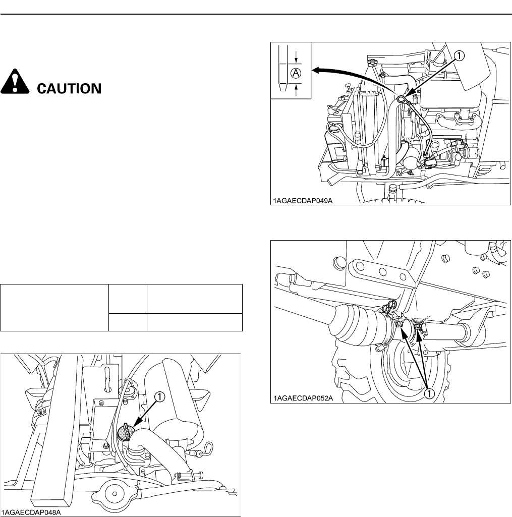
Proper upkeep of machinery is essential to ensure smooth operation and prevent costly breakdowns. Regular inspection and timely servicing can significantly extend the life of key components and minimize downtime. Some areas are more prone to wear and require particular attention during routine maintenance.
- Engine Cooling System: Regularly check the coolant levels and ensure the radiator is free from debris. Overheating can lead to engine damage.
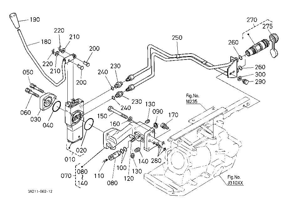
- Hydraulic System: Inspect hoses and connections for leaks. Low fluid levels or worn seals can cause reduced performance.
- Transmission: Check the transmission fluid levels and condition. Worn-out filters and fluids can lead to poor gear shifting and eventually transmission failure.
- Belts and Pulleys: Inspect for any signs of wear or damage, as worn belts can affect power transmission efficiency.
- Suspension System: Periodically inspect the suspension for any loose components or worn-out bushings, which can lead to instability and poor handling.
- Tires: Ensure proper tire pressure and check for any cracks, cuts, or wear patterns, which can affect traction and safety.
By staying proactive with these areas, you can prevent unexpected issues and ensure that the equipment performs at its best for years to come.
