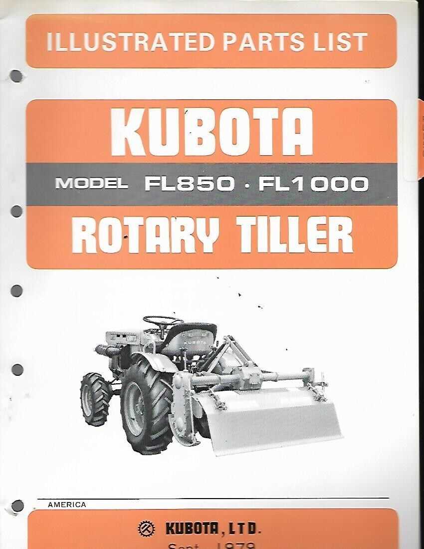
kubota tiller parts diagram

Understanding how the various elements of agricultural machinery interact is crucial for maintaining and repairing your equipment. Each section of the machine is composed of several interconnected parts, each with a specific role in ensuring the tool operates smoothly. Familiarizing yourself with the layout and the function of these components can greatly improve your ability to diagnose and resolve any issues that may arise.

In this guide, we will explore the detailed structure and key elements of one such machine, breaking down its core components. By gaining insight into the arrangement of these parts, you will be better prepared to perform routine checks, repairs, and replacements when necessary. This knowledge is invaluable for ensuring long-term reliability and optimal performance of your equipment.

Understanding Components of a Kubota Tiller
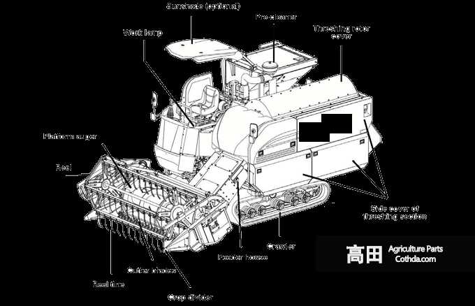
kubota tiller parts diagram

The effectiveness of any agricultural machine depends on the precise coordination of its various sections and mechanisms. Each element plays a vital role in ensuring smooth operation, from managing the soil to facilitating proper power transfer. By recognizing these elements, users can better maintain their equipment and ensure longevity in performance.

Main Structure and Framework Overview

kubota tiller parts diagram

The foundational components of this equipment are designed to provide stability, balance, and efficiency during operation. The structure supports various mechanical elements, ensuring smooth and reliable performance in different working conditions. Understanding the framework is essential to properly maintain and enhance the overall functionality of the device.

Core Elements

kubota tiller parts diagram

  • Chassis: The central frame that holds and supports all major components.
  • Axle assembly: Connects the wheels or attachments, ensuring proper movement and control.
  • Mounting points: Locations for attaching additional tools or accessories.

Support Mechanisms

kubota tiller parts diagram

  1. Stabilizers: Maintain balance during operation, especially on uneven terrain.
  2. Frame reinforcements: Strengthen the overall structure and prolong the lifespan.
  3. Protective covers: Shield internal components from damage or environmental

    Key Engine Elements and Functions

    kubota tiller parts diagram

    The smooth operation of any machine relies on the seamless interaction of its core mechanical components. Understanding these critical elements and how they contribute to overall performance is essential for ensuring longevity and efficiency. Each component plays a distinct role in maintaining power flow and regulating various processes.

    Combustion Chamber: This is where fuel and air mixtures ignite, generating the force required to move the pistons. Proper functioning ensures a consistent power supply for smooth operation.

    Pistons: These parts convert

    Drive Mechanism and Transmission Layout

    kubota tiller parts diagram

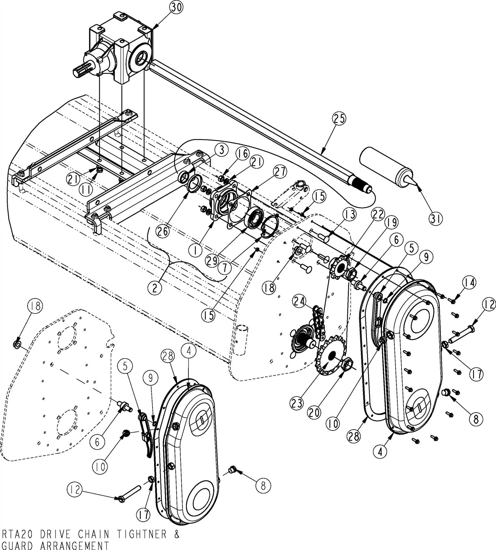
    The functioning of the drive and transmission system plays a critical role in ensuring smooth operation and effective power transfer. This section focuses on explaining how the arrangement of components enables motion and torque conversion, which is essential for reliable performance.

    Power transfer begins at the primary source, with energy being directed through a series of gears and shafts. These elements work together to ensure that the correct amount of force is applied to the operational mechanism, adapting to varying demands.

    Transmission layout is designed to maximize efficiency, with strategically placed components that allow seamless transitions between different speeds and levels of torque. This careful arrangement reduces wear

    Tiller Blade Assembly and Types

    The cutting mechanism plays a vital role in soil cultivation, ensuring effective preparation of the land for planting. Understanding how different cutting systems are assembled and the variations available can help optimize performance and longevity. Various designs offer distinct benefits depending on the type of soil and desired depth of cultivation.

    • L-shaped Blades: These blades are commonly used for lighter soil and provide a smooth cut, allowing efficient movement through soft surfaces.
    • C-shaped Blades: Designed for tougher conditions, these blades penetrate harder soil more effectively, ensuring deeper and more aggressive cutting.
    • Straight Blades: Often preferred for finer tilling, straight blades are suitable for shallow cuts, helping to break down soil without extensive disturbance.

      Power Delivery Systems and Their Role

      kubota tiller parts diagram

      Power delivery systems are essential components that facilitate the transfer of energy from the source to various mechanical units. These systems ensure that the necessary energy is efficiently supplied to operate the machinery, thereby enhancing overall functionality and performance. Understanding the intricacies of these systems is crucial for anyone involved in the maintenance and operation of heavy equipment.

      Within these frameworks, various elements work together to convert, regulate, and distribute energy effectively. This integration not only optimizes performance but also contributes to the longevity of the machinery. Proper management and upkeep of these systems play a significant role in minimizing downtime and preventing operational issues, making them vital for efficient equipment operation.

      In addition, a thorough comprehension of how energy is managed can lead to improved troubleshooting techniques. Recognizing the signs of malfunctioning components within the power delivery framework allows for timely interventions, ensuring that the machinery remains in optimal working condition. Ultimately, these systems are pivotal in achieving reliable and consistent performance in any mechanical application.

      Attachment Points and Mounting Connections

      Understanding the locations and methods for securing various implements is crucial for efficient operation and versatility. Proper attachment points ensure stability and reliability during use, allowing operators to switch between tools with ease.

      Key Connection Locations

      • Front Mounting Bracket: This area serves as the primary attachment for several accessories, providing a secure point for integration.
      • Side Connectors: Located on each side, these connections facilitate the installation of additional components and improve functionality.
      • Rear Coupling Points: Essential for attaching rear-mounted implements, these points ensure balanced weight distribution.

      Best Practices for Mounting

      1. Ensure all bolts and fasteners are tightened to the manufacturer’s specifications.
      2. Regularly inspect attachment points for wear and damage to maintain operational integrity.
      3. Utilize compatible adapters when switching between different tools to prevent misalignment.

      Handlebars and Control Levers Explanation

      kubota tiller parts diagram

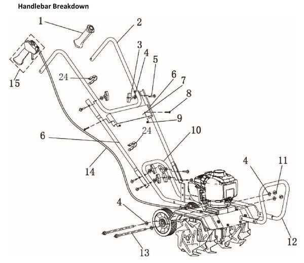
      The steering mechanism and control apparatus of garden equipment play a crucial role in ensuring effective operation. These components provide the user with the necessary interface to maneuver the machine and execute various functions. Understanding their design and functionality enhances the user’s ability to operate the equipment safely and efficiently.

      Design and Functionality

      The steering assembly typically comprises handles that allow for comfortable grip and maneuverability. These handles are often ergonomically designed to reduce strain during prolonged use. Control levers, strategically placed for easy access, enable the operator to engage different functions such as speed adjustment and direction changes. This thoughtful arrangement enhances the overall user experience, allowing for precise control and effortless operation.

      Maintenance Considerations

      kubota tiller parts diagram

      Regular inspection and maintenance of the steering system and control levers are essential for optimal performance. Operators should ensure that the handles are free of obstructions and that the levers move smoothly without any resistance. Lubrication of moving parts can prevent wear and tear, ensuring longevity and reliable functionality. Keeping these components in good condition contributes significantly to the machine’s overall efficiency and safety.

      Fuel System Configuration and Pathways

      The fuel system plays a crucial role in ensuring the efficient operation of machinery by delivering the necessary fuel to the engine. Understanding the configuration and pathways involved in this system is essential for effective maintenance and troubleshooting. This section explores the various components and flow of fuel, highlighting the importance of each element in maintaining optimal performance.

      At the heart of the fuel system lies the tank, which stores the fuel before it is transported to the engine. The fuel is drawn from the tank through a series of pipes and filters, ensuring that contaminants are removed before it reaches the combustion chamber. The configuration may vary depending on the specific machinery, but the fundamental principles remain the same.

Component Description
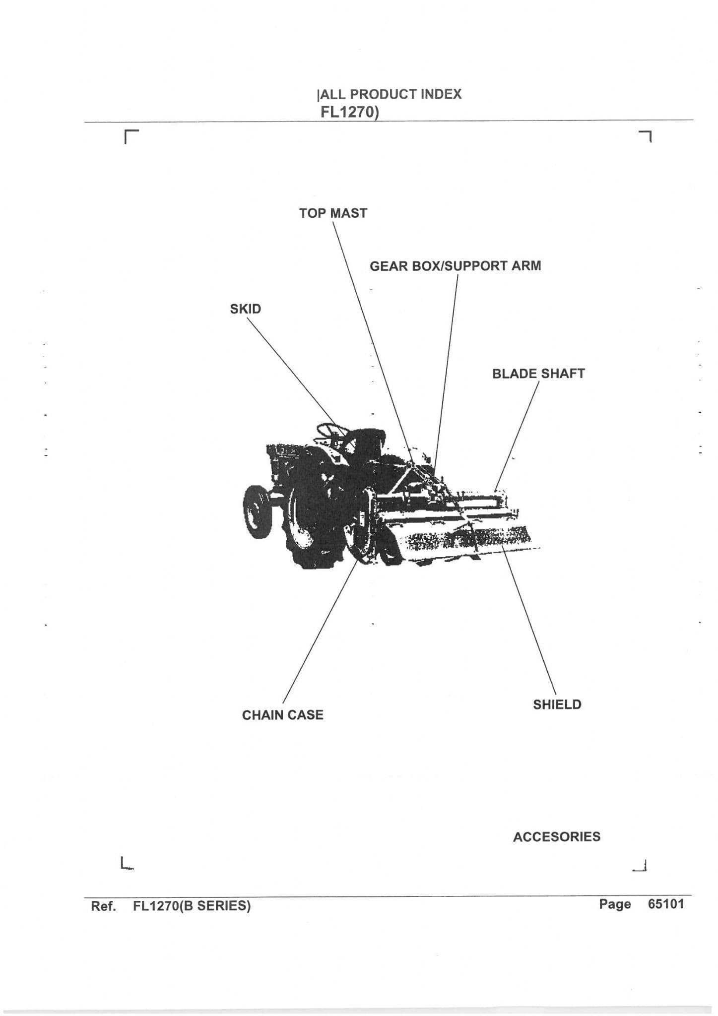
Rotary Blades Responsible for breaking and turning the soil, providing the foundation for efficient soil cultivation.
Gearbox Connects the power source to the rotating blades, adjusting the speed and torque for optimal ground engagement.
Transmission System Distributes power from the engine to the working parts, ensuring consistent and balanced operation.
Component Function
Fuel Tank Stores the fuel required for operation.
Fuel Pump Moves fuel from the tank to the engine.
Fuel Filter Removes impurities from the fuel before it enters the engine.
Fuel Injector Atomizes the fuel for efficient combustion within the engine.
Fuel Lines Transport fuel between the tank, pump, and engine components.

Each element of the fuel system is interconnected, creating a pathway that ensures fuel reaches the engine in a timely and efficient manner. Regular inspections and maintenance of these components can significantly enhance the longevity and performance of the machinery.

Hydraulic System Parts and Usage
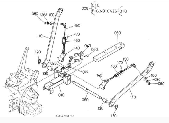
kubota tiller parts diagram

The hydraulic mechanism in agricultural machinery plays a crucial role in enhancing performance and operational efficiency. Understanding its components and functions is essential for effective maintenance and troubleshooting. This system primarily utilizes fluid power to facilitate various tasks, ensuring that the equipment operates smoothly under different conditions.

Key components of the hydraulic mechanism include:

  • Hydraulic Pump: This component generates flow and pressure, transforming mechanical energy into hydraulic energy.
  • Hydraulic Cylinder: Responsible for converting hydraulic energy back into mechanical energy, enabling movement of attached implements.
  • Control Valves: These regulate the flow and direction of the hydraulic fluid, allowing operators to control the speed and force applied by the machinery.
  • Reservoir: Stores hydraulic fluid, ensuring that the system has an adequate supply for operation.
  • Filters: Essential for maintaining fluid cleanliness, filters prevent contaminants from entering the system and causing damage.
  • Hoses and Fittings: These components transport hydraulic fluid between different parts of the system, facilitating effective communication and functionality.

Proper usage and maintenance of these components are vital for optimal performance. Regular checks and timely replacements can significantly extend the lifespan of the hydraulic system and enhance overall productivity. Understanding the role of each component allows for more informed decisions during operation and repair.

Maintenance Tips for Moving Components
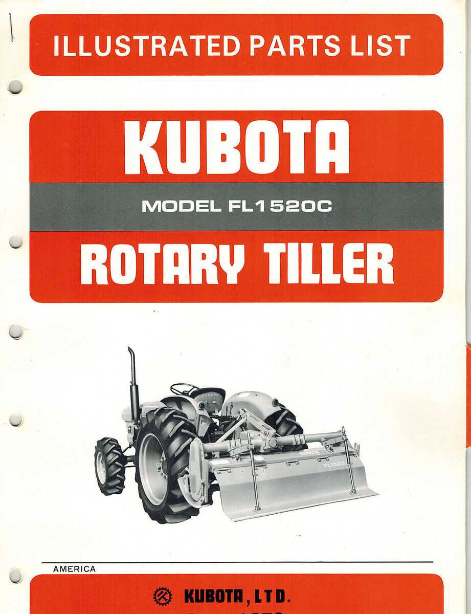
kubota tiller parts diagram

Ensuring the longevity and efficiency of any machinery requires regular attention to its mobile elements. These components are vital for optimal performance, and neglecting them can lead to malfunctions or decreased functionality. By implementing proper care techniques, users can maintain smooth operation and extend the lifespan of their equipment.

Regular Lubrication

Lubrication is crucial for reducing friction and wear between moving parts. Using the appropriate type of grease or oil as recommended by the manufacturer will help keep components operating smoothly. Be sure to check the lubrication levels regularly and apply new lubricant when necessary to prevent rust and corrosion.

Inspection and Cleaning

Frequent inspections of moving components are essential for identifying potential issues early. Look for signs of wear, damage, or unusual noise during operation. Additionally, keeping parts clean from dirt and debris can prevent buildup that may hinder performance. Regular cleaning can also enhance visibility for inspections and maintenance tasks.

Electrical Systems and Safety Features

The functionality and reliability of any agricultural machinery greatly depend on its electrical systems and integrated safety mechanisms. These components work together to ensure efficient operation while minimizing risks during use. Understanding these systems is essential for maintaining optimal performance and ensuring user safety.

Key Electrical Components
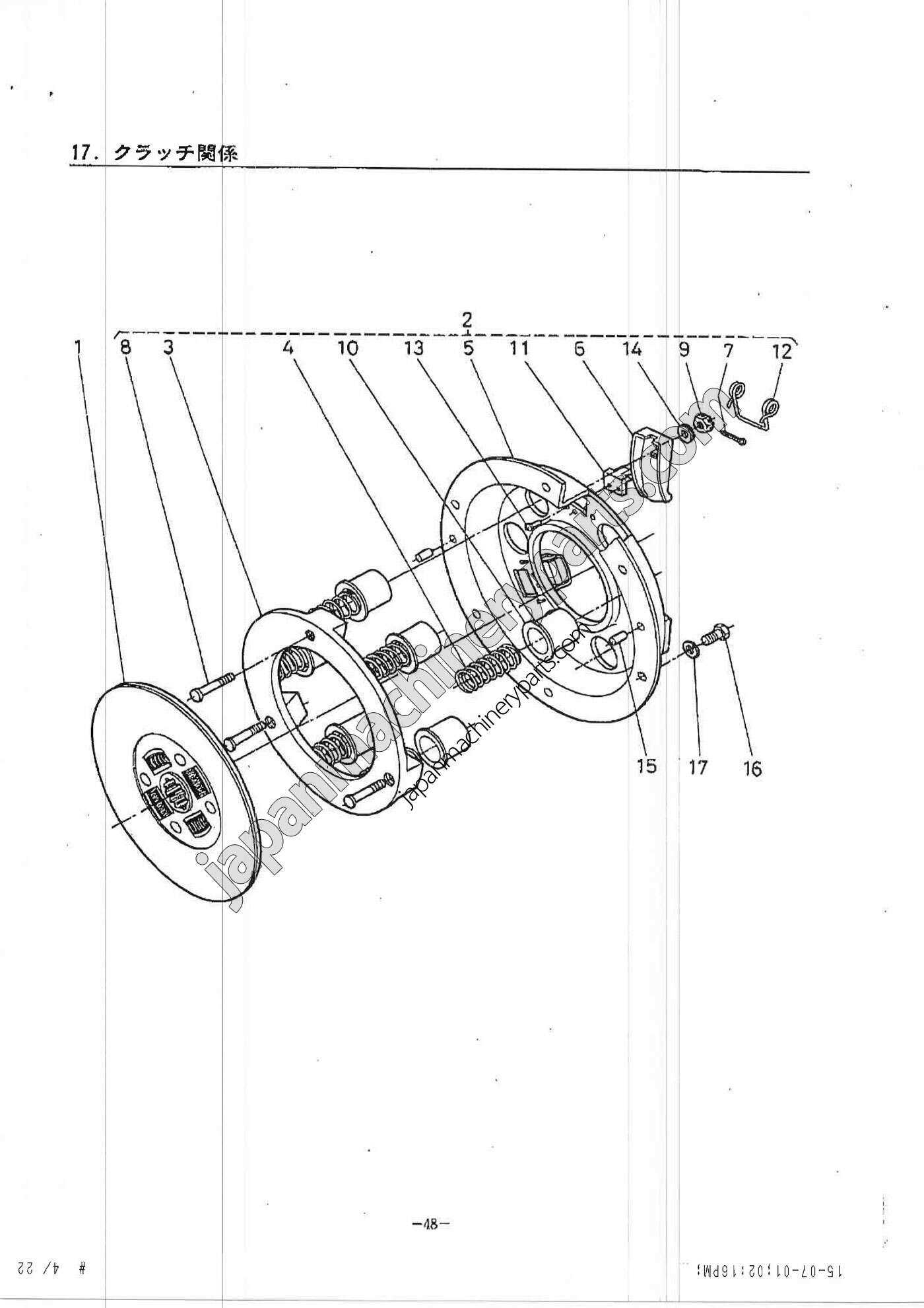
kubota tiller parts diagram

  • Power Supply: The source of energy that powers the entire unit, usually provided by a battery or alternator.
  • Wiring Harness: A network of wires that connects different electrical components, facilitating communication and power distribution.
  • Control Switches: Devices that allow the operator to manage various functions, enhancing usability and control.
  • Fuses and Relays: Safety devices that protect electrical circuits from overloads, preventing potential damage.

Safety Features
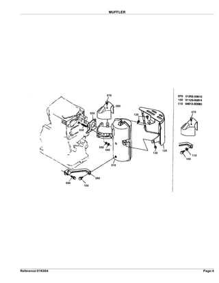
kubota tiller parts diagram

  1. Emergency Stop Mechanism: A crucial feature that allows the operator to immediately halt operation in case of an emergency.
  2. Overload Protection: Systems designed to automatically shut down the machinery when excessive load is detected, preventing mechanical failures.
  3. Grounding Systems: Essential for preventing electrical shocks by providing a safe path for electricity to ground.
  4. Warning Lights and Alarms: Indicators that alert the operator to potential issues, ensuring timely responses to problems.