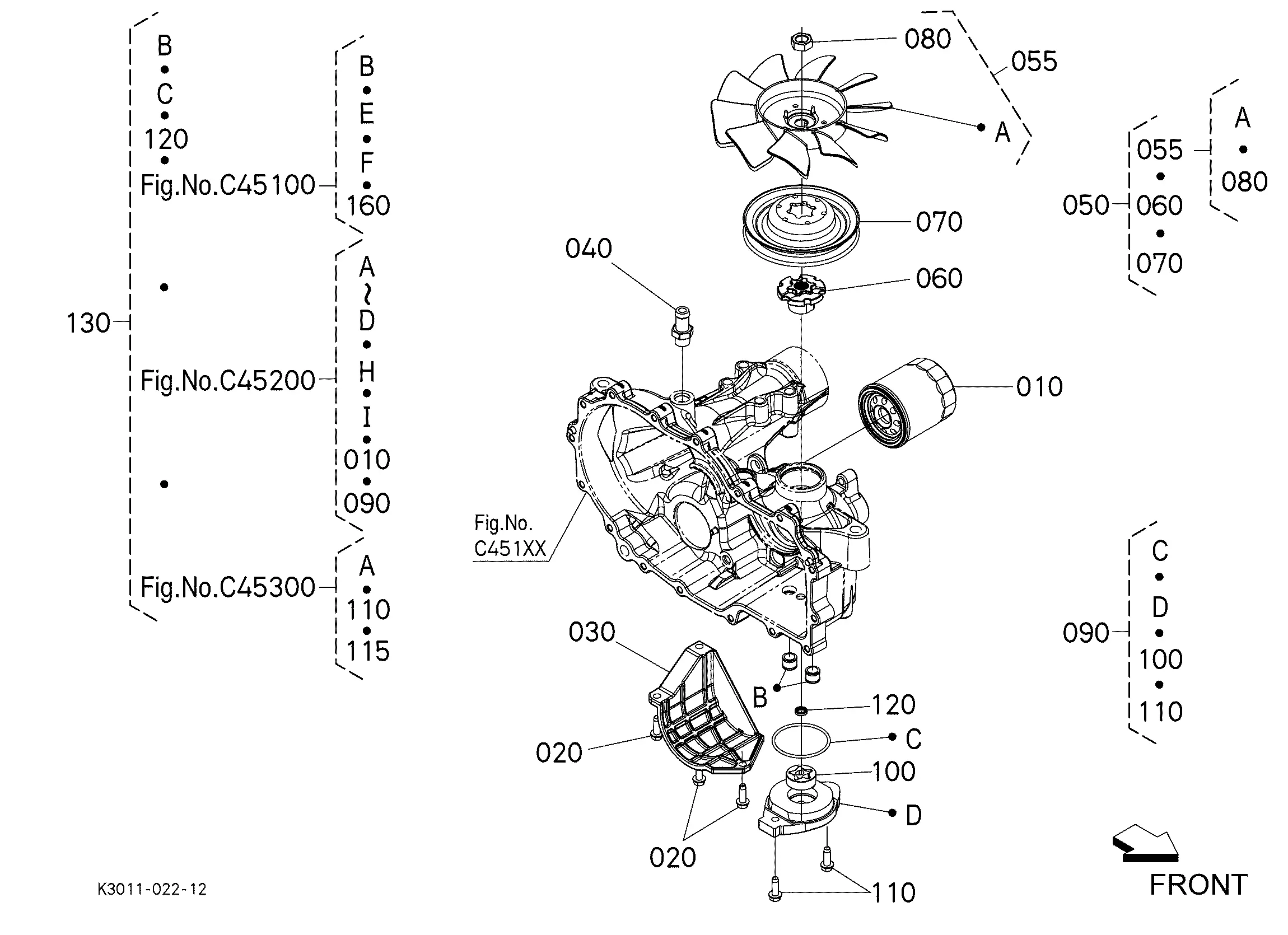
Understanding the detailed structure of a machine is essential for anyone seeking to maintain or enhance its performance. With the right visual guide, it’s possible to identify every element, ensuring smooth operation and efficient repairs. This guide will provide clarity and insight into the inner workings, helping to keep everything running seamlessly.
Exploring the various assemblies and their specific functions offers a clearer picture of how each piece fits together. Knowing how to identify the components and their locations can save time and prevent mistakes, whether you’re addressing routine maintenance or tackling more complex repairs.
By diving into the specific layout and connections, you’ll gain a deeper understanding of how the entire system functions. This not only improves troubleshooting but also aids in maximizing the longevity and efficiency of the machinery.
Kubota Z125SKH-54 Parts Overview
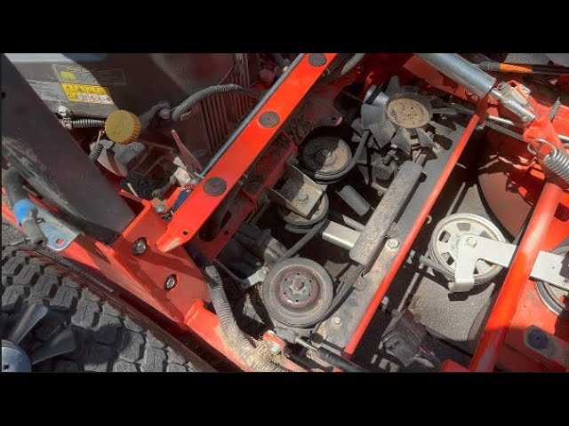
The mechanical design of this lawn tractor model is known for its efficient and durable construction. With a focus on high-performance and long-term reliability, the machine is built to handle demanding tasks in various environments. Its components are specifically engineered to ensure optimal functioning, offering smooth operation and minimizing the need for frequent adjustments.
Key elements of the machine contribute to its exceptional performance, including a reinforced frame and specialized features designed to handle rough conditions. These essential mechanisms work together to deliver stability and precise control, ensuring a consistent and effective use of the equipment.
Maintenance and proper care of each component is crucial for extending the machine’s lifespan. Regular checks and appropriate upkeep can prevent unexpected issues and ensure continuous smooth operation. High-quality materials and precise craftsmanship make the unit resilient, even under intensive use.
Engine Components Breakdown
The internal structure of the motor is composed of several key elements that work together to ensure smooth and efficient performance. Understanding these individual elements and how they interact provides insight into how the engine operates as a cohesive unit. Below is a detailed breakdown of the primary components and their roles within the system.
Main Components
- Pistons: These move up and down within the cylinders, converting fuel into mechanical energy.
- Cylinders: The chambers where the combustion process occurs, housing the pistons.
- Crankshaft: Converts the linear motion of the pistons into rotational motion, driving other systems.
Support Systems
- Cooling System: Maintains optimal temperatures by circulating coolant throughout the engine block.
- Lubrication System: Ensures that moving parts are properly lubricated to reduce friction and wear.
- Fuel Injection: Delivers the right amount of fuel into the combustion chambers for efficient power generation.
Transmission and Drive System Parts
The transmission and drive mechanisms are critical to the performance and efficiency of any lawn mower. These systems work together to ensure smooth operation, transferring power from the engine to the wheels while maintaining stability and control. The components involved in these functions must be durable and well-maintained to guarantee reliable operation over time.
Key Drive Components
The drive system includes essential elements such as belts, pulleys, and axles. These components are designed to manage the flow of power, ensuring the equipment moves smoothly across various terrains. Regular checks and adjustments of these mechanisms are crucial to avoid breakdowns and ensure the system performs at its best.
Transmission Maintenance
Transmission systems require periodic inspections to ensure their long-term efficiency. Proper lubrication, fluid levels, and occasional part replacements are necessary to maintain seamless gear shifts and reduce strain on the drive components. Staying ahead of potential issues will prevent costly repairs and extend the life of the equipment.
Hydraulic System Diagram
The hydraulic system operates through fluid dynamics to manage various mechanical functions. It utilizes pressurized liquid to transmit power, allowing for the movement and control of key components within the machinery. This system is crucial for ensuring efficient operation and handling tasks that require substantial force.
The structure of this system includes multiple essential elements working together:
- Pumps that generate the necessary pressure
- Cylinders and motors that convert the pressure into mechanical movement
- Valves to control fluid flow and regulate pressure levels
- Hoses and fittings to ensure fluid movement between different parts
- Reservoirs that store and supply the hydraulic fluid
Maintaining each of these elements is vital for the smooth operation of the entire mechanism, as any failure could lead to reduced performance or breakdown.
Steering Mechanism Components
The steering system is essential for controlling the direction of movement, ensuring smooth and precise handling. It consists of multiple interconnected elements working together to allow the operator to adjust the orientation efficiently. This coordination of different components provides stable and responsive navigation, ensuring both safety and ease of use. Each part contributes to the overall operation, making the steering mechanism highly dependable in various conditions.
| Component | Function |
|---|---|
| Steering Wheel | Controls the direction by transmitting inputs from the operator. |
| Steering Column | Connects the wheel to other parts, ensuring smooth rotation and support. |
| Steering Linkage | Transfers motion from the column to the front wheels. |
| Front Axle | Houses the steering components and allows the front wheels to pivot. |
| Tie Rods | Maintain alignment of the front wheels while steering. |
Fuel System Parts Layout
The fuel system is crucial for the efficient operation of machinery, ensuring that the engine receives the appropriate amount of fuel for optimal performance. Understanding the components involved in this system can help with maintenance and troubleshooting, ultimately prolonging the life of the equipment.
Key Components
Several essential elements constitute the fuel mechanism, each playing a vital role in the delivery and regulation of fuel. The fuel tank holds the liquid, while the fuel pump facilitates movement to the engine. Additionally, fuel filters are necessary to remove impurities, ensuring clean fuel reaches the combustion chamber.
Flow Mechanism
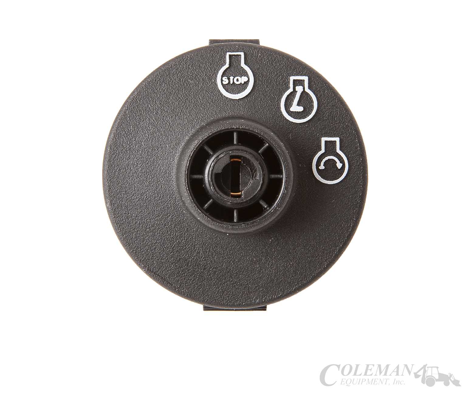
The flow of fuel begins at the storage unit, from where it is drawn by the pump. This liquid then travels through the filters before entering the engine. Proper functioning of each component is essential to prevent issues such as clogging or pressure loss, which can lead to reduced efficiency and performance.
Cooling System Components
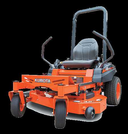
The cooling system plays a crucial role in maintaining optimal operating temperatures for machinery. It is designed to prevent overheating and ensure efficient performance during various tasks. Understanding the key elements of this system can aid in proper maintenance and troubleshooting.
- Radiator: This component dissipates heat from the coolant, allowing it to cool before returning to the engine.
- Water Pump: This pump circulates coolant throughout the engine and radiator, ensuring efficient heat transfer.
- Thermostat: Regulates coolant flow based on temperature, allowing the engine to reach optimal operating temperature quickly.
- Coolant Hoses: Flexible tubes that transport coolant between components, maintaining the necessary flow within the system.
- Coolant Reservoir: Holds excess coolant and provides a source for the system when needed, preventing air from entering.
Regular inspection and maintenance of these components are essential for the longevity and efficiency of the cooling system. Identifying issues early can help avoid more severe problems in the future.
Electrical System Overview
The electrical system of a machinery unit plays a crucial role in its overall performance and functionality. It serves as the backbone that powers various components, ensuring seamless operation and control. Understanding the layout and components of this system is essential for efficient maintenance and troubleshooting.
Key Components
This system typically consists of a battery, wiring harnesses, fuses, and various sensors. The battery provides the necessary electrical energy to start the engine and operate essential functions. Wiring harnesses connect different parts, facilitating the flow of electricity throughout the machine. Fuses act as safety devices, preventing overloads and protecting sensitive components from damage.
Importance of Maintenance
Regular inspection and maintenance of the electrical system are vital for preventing malfunctions and ensuring optimal performance. Checking connections, testing voltage levels, and replacing worn-out components can significantly extend the lifespan of the machinery and enhance its reliability during operation.
Cutting Deck Parts Configuration
The cutting deck is a crucial component in achieving efficient lawn maintenance. Understanding the arrangement of its elements can enhance performance and ensure optimal results during operation. This section will explore the various elements that constitute the cutting deck, highlighting their roles and interconnections.
Key Components Overview
Several primary components make up the cutting deck, each serving specific functions. The blades are responsible for achieving a clean cut, while the deck housing supports these blades and maintains structural integrity. Additionally, the spindle assemblies play a vital role in rotating the blades, contributing to the overall effectiveness of the mowing process.
Assembly and Maintenance Insights
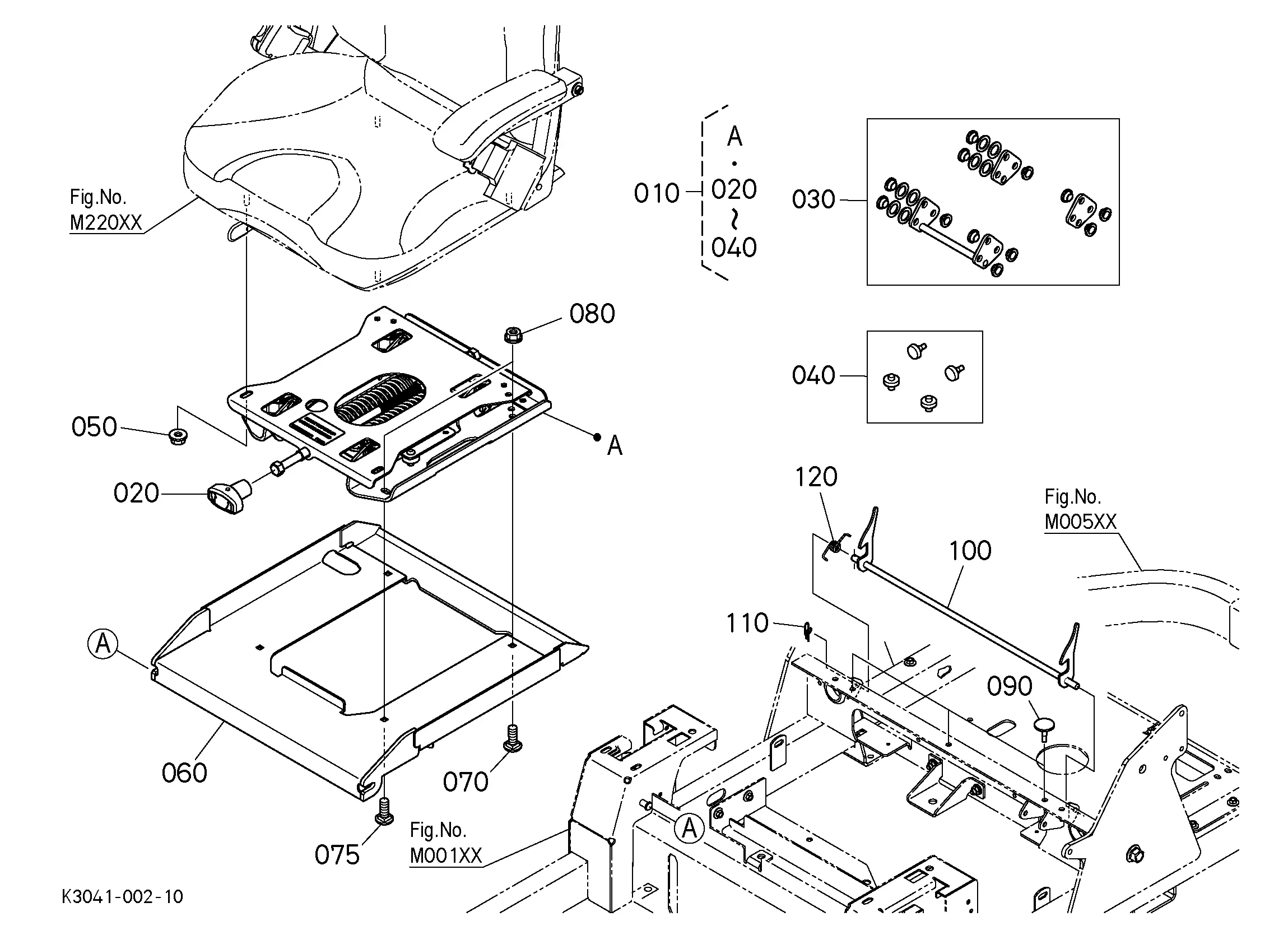
Proper assembly and maintenance of the cutting deck components are essential for longevity and performance. Regular checks on blade sharpness and spindle functionality will ensure a consistent cut quality. Furthermore, keeping the deck clean from debris will prevent potential damage and enhance efficiency during operation.
Suspension and Frame Diagram
The suspension system and chassis design play a vital role in the overall performance and stability of any machinery. Understanding these components is essential for effective maintenance and troubleshooting. A well-structured frame combined with a robust suspension ensures optimal handling and comfort during operation.
Key elements of the suspension and frame assembly include:
- Frame Structure: The main body that supports various components and provides rigidity.
- Suspension Arms: Parts that connect the wheels to the frame, allowing for movement and flexibility.
- Shock Absorbers: Devices that dampen impacts, enhancing ride quality and stability.
- Springs: Components that support weight and absorb shocks from uneven surfaces.
- Mounting Points: Areas where the suspension system is attached to the frame.
To ensure longevity and efficiency, regular inspection and maintenance of these components are recommended. Identifying wear or damage early can prevent costly repairs and enhance performance.
Exhaust System Parts List
The exhaust system plays a crucial role in ensuring optimal performance and efficiency of the engine. This section outlines the essential components that make up this system, contributing to effective emissions control and overall functionality. Understanding these elements is vital for maintenance and repair, as each part serves a specific purpose in the exhaust process.
Key Components of the Exhaust System
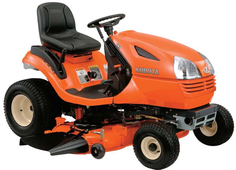
1. Exhaust Manifold: This part collects gases from the engine cylinders and directs them to the exhaust pipe.
2. Catalytic Converter: A critical element that reduces harmful emissions by converting them into less harmful substances.
3. Resonator: This component works to minimize noise and can enhance sound quality, making it an integral part of the exhaust system.
4. Muffler: Responsible for reducing noise produced by the exhaust gases before they exit the vehicle.
5. Exhaust Pipe: It channels the exhaust gases from the engine to the outside atmosphere, completing the exhaust flow process.
Importance of Regular Maintenance

Routine inspection and replacement of these components are essential to maintain peak efficiency and performance. Neglecting these parts can lead to decreased engine performance, increased emissions, and potential engine damage.
Braking System Components
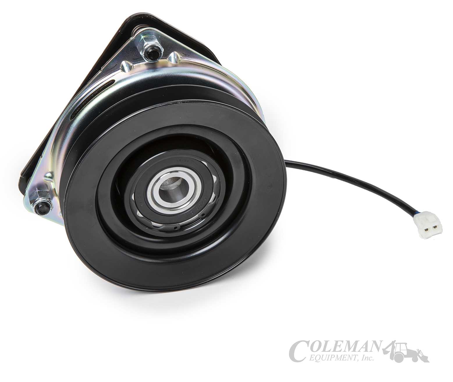
The braking mechanism is a critical element in ensuring safety and control in various machinery. This system consists of several interconnected parts that work together to halt motion effectively. Understanding these components is essential for maintaining optimal performance and reliability.
Brake Pedal: This is the primary control for activating the braking system. It provides the necessary leverage for the operator to apply force to the braking components.
Brake Lines: These are the conduits through which hydraulic fluid travels, transmitting pressure from the brake pedal to the braking mechanism, enabling efficient operation.
Brake Calipers: Calipers house the brake pads and are responsible for applying pressure to the brake discs when the brake pedal is engaged. This action generates friction, which slows down the vehicle.
Brake Pads: Positioned within the calipers, these friction materials come into contact with the brake discs to create the necessary stopping power. They are vital for effective deceleration.
Brake Discs: Also known as rotors, these components rotate with the wheels and are gripped by the brake pads to slow down or stop the machinery.
Master Cylinder: This component converts the force applied on the brake pedal into hydraulic pressure, which is then distributed through the brake lines to activate the calipers.
Understanding each part’s role helps in diagnosing issues and ensuring the braking system operates smoothly, ultimately enhancing the safety and efficiency of the equipment.
Maintenance and Service Parts
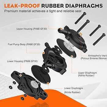
Regular upkeep and replacement of essential components are crucial for ensuring optimal performance and longevity of your equipment. Understanding the various elements that require attention can greatly enhance operational efficiency. This section highlights key aspects of maintenance and essential service components that contribute to the effective functioning of your machine.
Essential Maintenance Components
Among the fundamental aspects of upkeep, filters, fluids, and belts play significant roles. Filters should be inspected and replaced periodically to maintain clean airflow and fluid circulation. Additionally, checking and topping up fluids is vital for preventing overheating and ensuring smooth operation. Regular examination of belts for wear and tension is also recommended to avoid unexpected breakdowns.
Service Intervals and Recommendations
Following a structured maintenance schedule is key to preserving functionality. Consult the manufacturer’s guidelines for recommended service intervals. Frequent inspections and timely replacements not only improve reliability but also extend the lifespan of various system components. Establishing a routine will ensure that your equipment remains in optimal condition and ready for use when needed.