Lastly, exhaust ports expel hot air, ensuring the system stays cool
Internal Fuel System Breakdown
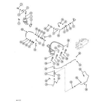
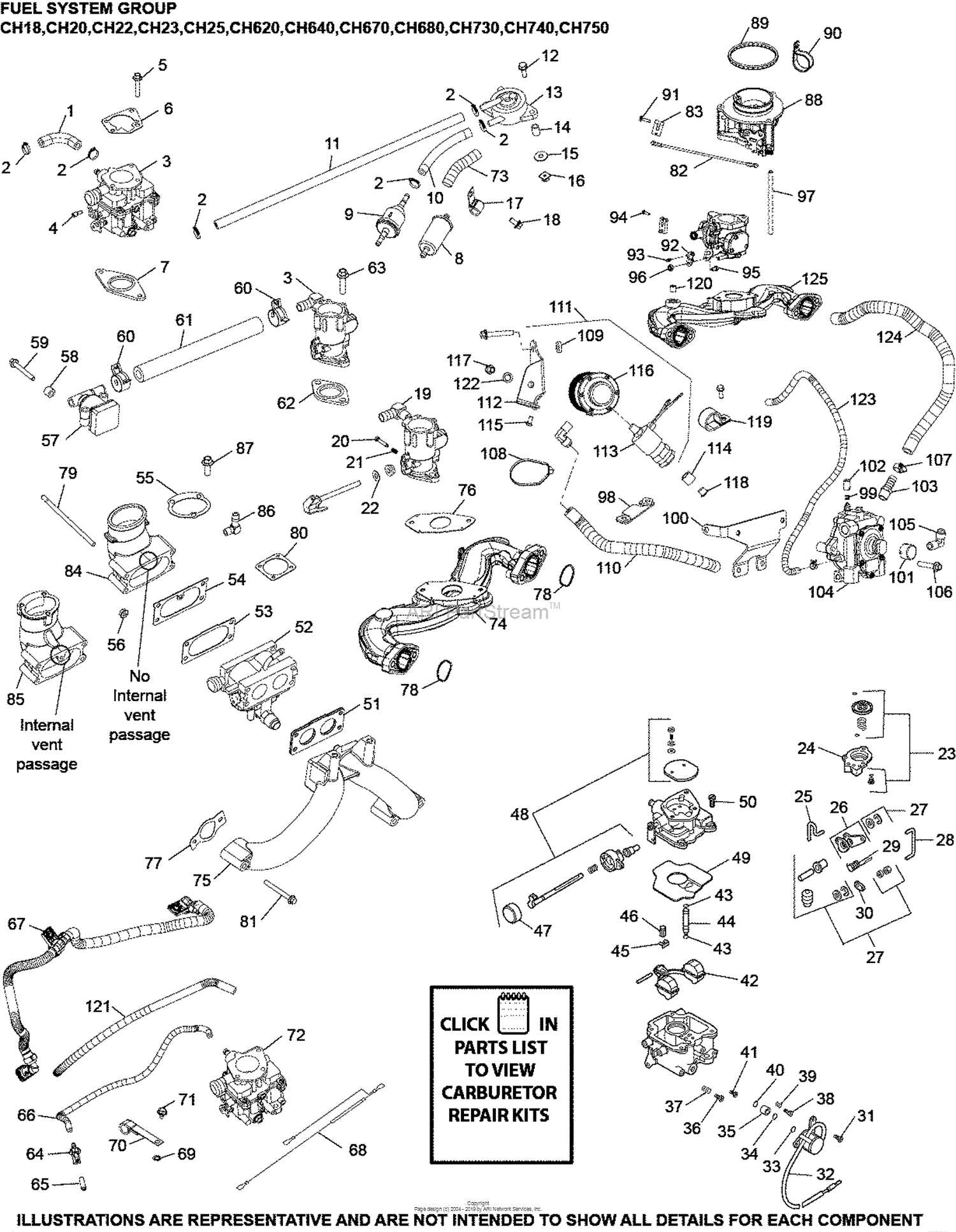
The internal combustion process relies heavily on a well-functioning fuel system. This component ensures the efficient delivery of fuel to the engine, allowing for optimal performance and longevity. A well-maintained system guarantees the smooth operation of the equipment by regulating the flow of fuel from the storage tank to the engine’s combustion chambers.
Fuel Delivery Path: The process begins with the fuel being drawn from the main storage compartment and passed through a series of filters. These filters remove impurities, ensuring that only clean fuel reaches the combustion area. Clean fuel is crucial to prevent clogging and ensure efficient energy production.
Filtration and Regulation: Once the fuel is filtered, it is controlled by pressure regulators, which maintain a stable and consistent flow. This precise control ensures that the system responds accurately to the demands of the engine, adjusting the fuel supply according to the load and operational conditions.
Component Integrity: Regular inspection of the fuel system’s components is essential. Key areas such as hoses, filters, and connectors must be checked to prevent leaks or blockages. Any malfunction in these parts can lead to reduced efficiency or even system failure.
Starter Assembly and Functionality
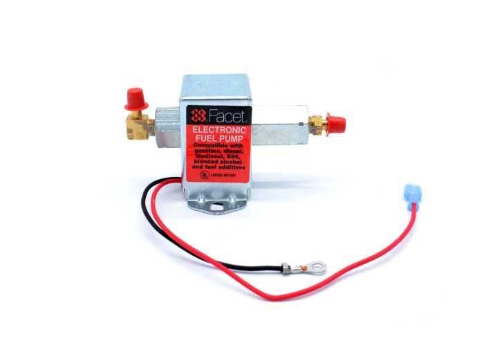
The starter system is a crucial component in initiating the operation of an engine. It converts electrical energy into mechanical energy, enabling the engine to begin its cycle. This assembly typically includes various parts that work harmoniously to ensure a smooth start, contributing to the overall efficiency of the machinery.
Components of the Starter Assembly
- Starter Motor: This is the primary element that provides the necessary torque to turn the engine’s flywheel.
- Solenoid: Often mounted on the starter motor, it acts as a switch to engage the starter when the ignition is activated.
- Drive Gear: This gear engages with the flywheel, allowing the motor to crank the engine.
- Electrical Connections: These wires connect the battery to the starter, delivering the required power for operation.
Functionality of the Starter System
- When the ignition switch is turned on, power flows to the solenoid.
- The solenoid engages, pushing the drive gear into the flywheel.
- The starter motor then spins, turning the flywheel and cranking the engine.
- Once the engine starts, the ignition switch is released, disengaging the solenoid and stopping the motor.
Understanding the components and functionality of the starter system is essential for effective maintenance and troubleshooting. Regular checks can prevent issues and ensure reliable performance, enhancing the longevity of the equipment.
Exhaust System and Its Components
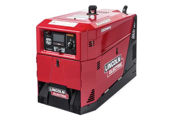
The exhaust assembly plays a crucial role in managing the byproducts of combustion, ensuring that harmful gases are effectively expelled from the engine. Understanding the various elements of this system is essential for maintenance and performance optimization. Each component contributes to the overall functionality, enhancing the vehicle’s efficiency and environmental compliance.
Main Components of the Exhaust System
- Exhaust Manifold: This part collects gases from the engine cylinders and directs them into the exhaust piping.
- Catalytic Converter: It reduces harmful emissions by converting toxic gases into less harmful substances through chemical reactions.
- Resonator: This component helps to eliminate specific sound frequencies, improving the overall acoustic quality of the exhaust note.
- Muffler: Its primary function is to reduce noise produced by the exhaust gases, providing a quieter driving experience.
- Exhaust Pipe: These pipes transport the gases from the engine to the rear of the vehicle, allowing for efficient expulsion.
Importance of Each Component
- Exhaust Manifold: Ensures optimal gas flow from the engine, enhancing performance.
- Catalytic Converter: Plays a vital role in emissions control, supporting environmental standards.
- Resonator: Balances sound levels, contributing to a refined auditory experience.
- Muffler: Essential for maintaining comfort within the cabin by minimizing noise.
- Exhaust Pipe: Crucial for maintaining proper exhaust flow, preventing back pressure.
Welding Circuit and Output Terminals
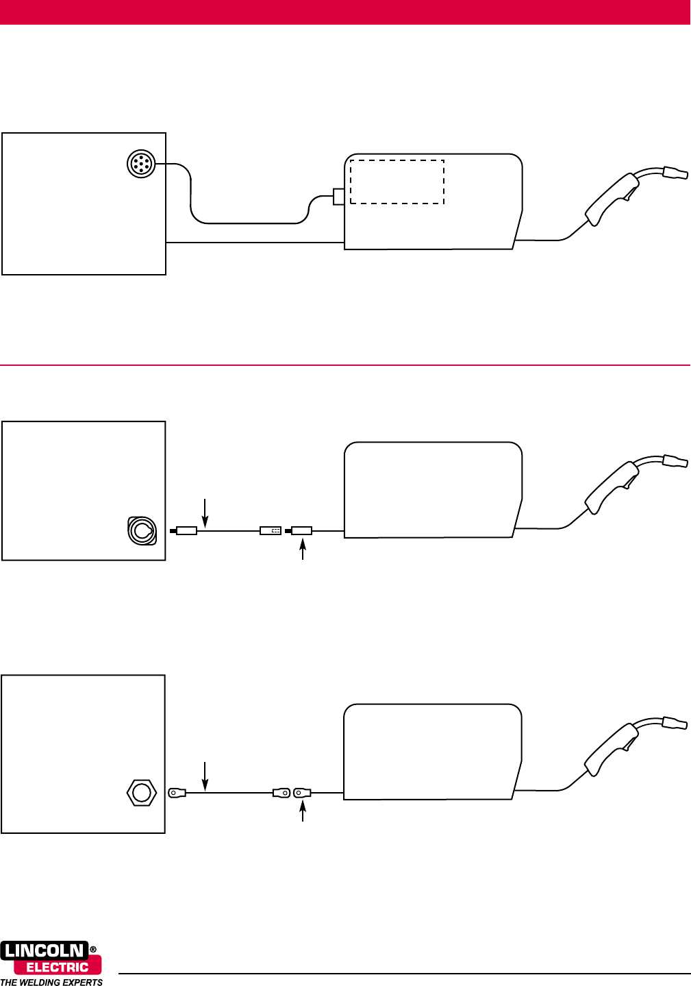
The welding circuit plays a critical role in the functionality of electric arc tools, enabling the creation of high-quality welds through controlled electrical pathways. Understanding the components involved in this circuit is essential for ensuring optimal performance and safety during operations. This section will delve into the essential elements of the welding circuit, including how output terminals facilitate the transfer of current to the welding electrode.
Understanding the Circuit Components
The welding circuit typically consists of various elements such as transformers, rectifiers, and contactors that work together to regulate voltage and current. These components help maintain a stable arc during the welding process. The transformer adjusts the input voltage to a suitable level for welding, while the rectifier converts alternating current (AC) to direct current (DC), if necessary. This combination is crucial for achieving the desired welding characteristics.
Output Terminals: Their Role and Functionality
Output terminals serve as the interface between the welding equipment and the electrode holder or workpiece. They are designed to deliver the necessary current efficiently and safely. Typically, these terminals are robust and insulated to prevent electrical hazards. Proper connection to the workpiece and the electrode holder ensures a stable arc and high-quality welds. Regular maintenance of output terminals is essential for reliable operation and longevity of the welding equipment.
Control Panel Layout and Switch Functions
The arrangement of the control interface plays a crucial role in the efficient operation of equipment. Understanding the various components and their respective functionalities is essential for optimal usage. This section explores the configuration of controls and their intended actions, aiding users in navigating and utilizing the system effectively.
Key Elements of the Control Interface
At the forefront of the control panel are various switches and indicators that allow users to manipulate the machine’s settings. Each switch is designed for a specific purpose, such as activating the power, adjusting settings, or monitoring performance. The layout is strategically organized to ensure ease of access and visibility, allowing operators to make quick adjustments as needed.
Functions of Individual Switches
Each control switch serves a distinct function. For instance, the main power switch initiates the operation, while adjustment knobs regulate output levels. Additionally, indicator lights provide essential feedback on the system’s status, alerting users to any abnormalities. Familiarity with these functions enables operators to troubleshoot issues efficiently and maintain optimal performance.
Conclusion
Mastering the layout and functionalities of the control panel is vital for effective operation. A thorough understanding of each component not only enhances user experience but also contributes to the longevity and reliability of the equipment.
Maintenance Points and Access Areas
Understanding the critical areas for upkeep and access can significantly enhance the longevity and performance of machinery. This section highlights essential zones that require regular inspection and maintenance to ensure optimal functioning. Proper attention to these regions can prevent unexpected failures and enhance operational efficiency.
Key Maintenance Zones
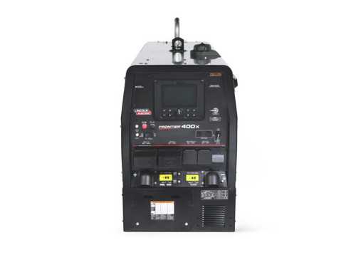
The primary maintenance zones typically include the engine compartment, fuel system, and electrical components. Regular checks in these areas can help identify potential issues before they escalate. For instance, monitoring fluid levels, inspecting belts and hoses, and ensuring that connections are secure are crucial steps in preserving machinery health.
Accessing Essential Components
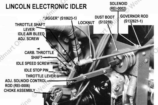
Gaining access to vital components often involves following specific protocols. Most equipment features panels or access points that facilitate easy inspection and servicing. Utilizing appropriate tools and adhering to safety guidelines is imperative when working in these areas. Additionally, consulting the manufacturer’s guidelines can provide valuable insights into best practices for accessing and maintaining crucial parts.
Detailed View of the Alternator Setup
The alternator setup is a crucial component that plays a significant role in the overall functionality of the power generation system in various machinery. This system is responsible for converting mechanical energy into electrical energy, ensuring that the electrical components operate efficiently. Understanding the intricacies of this assembly allows for better maintenance and troubleshooting, ultimately enhancing the machine’s performance and longevity.
Components Involved
Key elements in the alternator configuration include the rotor, stator, voltage regulator, and various mounting brackets. Each part has a specific function that contributes to the effective generation of electricity. Below is a brief overview of these components:
| Component |
Function |
| Rotor |
Creates a magnetic field as it rotates, essential for inducing current. |
| Stator |
Houses the windings where electricity is generated when exposed to the magnetic field. |
| Voltage Regulator |
Maintains a consistent voltage level to prevent damage to electrical components. |
| Mounting Brackets |
Secures the alternator in place, ensuring proper alignment and operation. |
Maintenance Considerations
Regular checks of the alternator setup are essential for optimal performance. Inspecting the connections, ensuring proper tension on belts, and monitoring the output voltage can prevent potential issues. Addressing any signs of wear or malfunction promptly helps maintain the reliability of the electrical system.
Protective Housing and External Covers
The protective enclosures and outer shells of equipment serve crucial roles in ensuring durability and functionality. These components are designed to shield internal mechanisms from external factors such as dust, moisture, and mechanical impact. By providing a reliable barrier, they help maintain the performance and longevity of the device, making them essential for both operational efficiency and user safety.
Material Selection and Durability
The choice of materials for protective covers is vital for optimal performance. High-quality plastics, metals, and composite materials are commonly used to enhance resistance against environmental challenges. Each material offers unique benefits, from lightweight designs to robust shielding, ensuring that the equipment remains functional in various conditions.
Maintenance and Inspection
Regular maintenance and thorough inspection of protective housings are necessary to identify any wear or damage that may compromise the equipment’s integrity. Ensuring that these outer layers are free from cracks and corrosion helps in upholding their protective features. Users should follow recommended guidelines for cleaning and care to prolong the lifespan of these essential components.
| Material |
Benefits |
Common Uses |
| Plastic |
Lightweight, corrosion-resistant |
Small equipment enclosures |
| Aluminum |
Strong, lightweight, heat-dissipating |
Outdoor machinery covers |
| Composite |
High durability, weather-resistant |
Heavy-duty applications |


