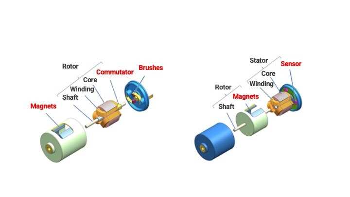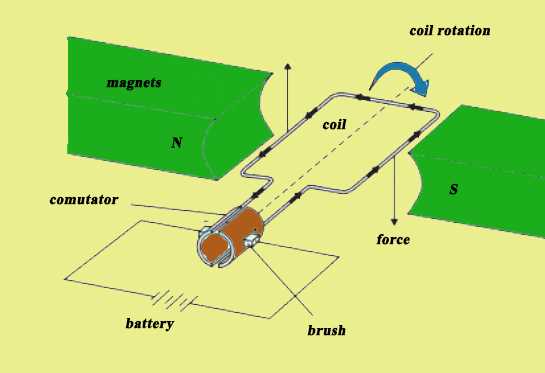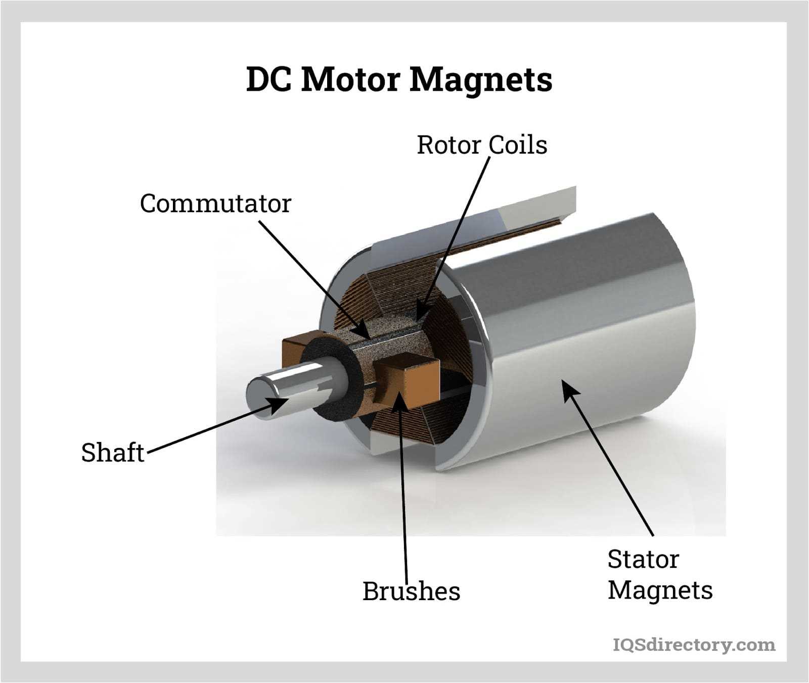
In various applications, devices powered by direct current provide controlled movement essential for both industrial and household uses. Their structure is composed of several elements, each contributing to smooth and efficient operation. A closer look at these systems reveals how energy flows and components work in harmony to achieve desired performance.
Key components play distinct roles in ensuring stability and functionality. From the heart of the system that initiates movement to the smaller elements that enhance precision, everything is designed to fulfill specific tasks. The interplay among these sections is what guarantees both speed and direction are managed accurately.
Efficient design means not only simplicity but also robustness. Learning about the arrangement of such devices provides deeper insight into how different technologies contribute to long-lasting and optimized results. Understanding these elements can help users better maintain and troubleshoot their equipment.
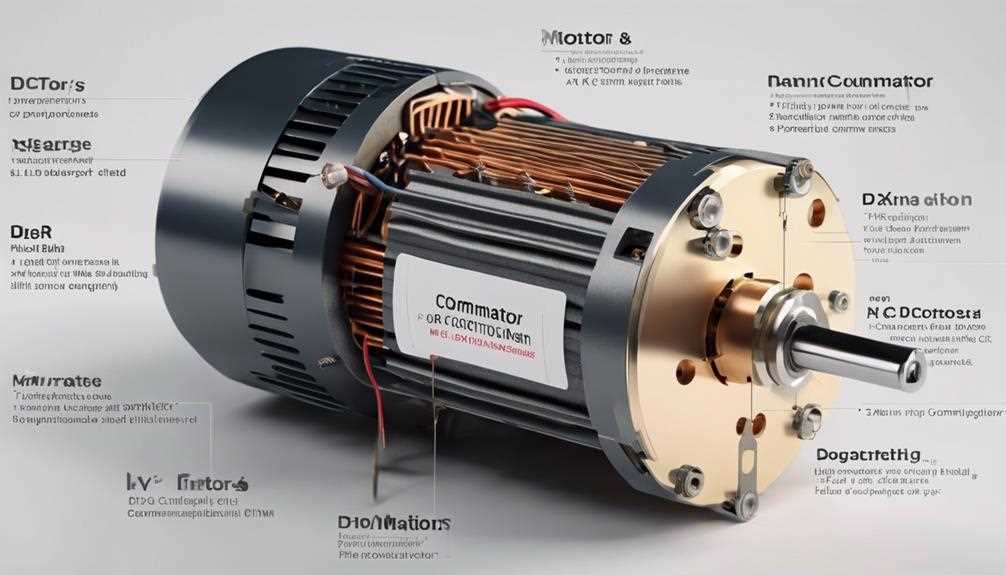
DC Motor Diagram with Parts
A device driven by electrical energy features several interconnected components working together to generate movement. Understanding how these elements interact helps in troubleshooting and designing efficient systems for various applications.
Key Elements Involved
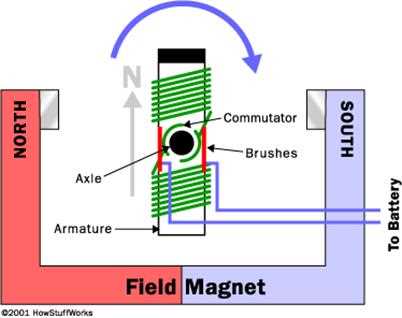
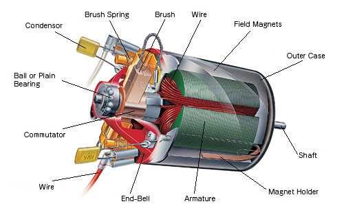
- Coil Assembly: A winding of conductive wire that produces a magnetic field when energized.
- Commutator: A rotating switch that ensures consistent current direction within the system.
- Brushes: Components in contact with the rotating part, delivering electrical power.
- Shaft: The central rod that transfers rotational energy to external systems.
Interaction of Components
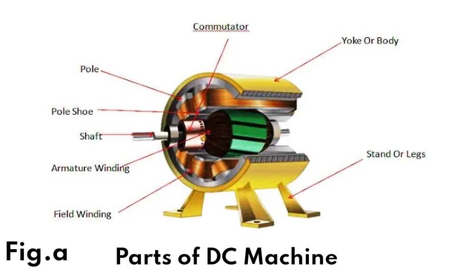
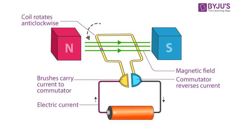
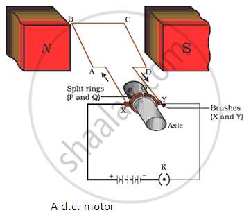
- Electric current flows through the winding, creating a magnetic force.
- The rotating section, guided by the commutator, aligns with the magnetic field to produce motion.
- The shaft transfers this motion to the required application, enabling mechanical work.
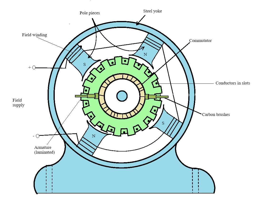
- Coils: These are essential for creating electromagnetic fields when energized.
- Permanent Magnets: Provide the stable magnetic field needed for interaction.
- Armature: A key part that rotates under the influence of magnetic forces.
- Protection: The casing safeguards sensitive elements from external damage, dust, and moisture.
- Support: It serves as a stable base that maintains the alignment of internal components, ensuring smooth operation.
- Cooling: Effective airflow management through the structure helps dissipate heat generated during operation, preventing overheating.
- Noise Reduction: A well-designed enclosure can minimize vibrations and noise, contributing to a quieter environment.
- Aluminum: Lightweight and resistant to corrosion, making it an ideal choice for many applications.
- Steel: Provides robust strength and durability, suitable for heavy-duty environments.
- Plastic: Offers versatility and ease of manufacturing, often used in less demanding scenarios.
- Open-loop Systems: These rely on predetermined commands without feedback, suitable for simple tasks.
- Closed-loop Systems: Incorporate feedback mechanisms to adjust actions based on performance, enhancing accuracy.
- Controllers: Devices that process input signals and determine the necessary adjustments for performance.
- Actuators: Mechanisms that execute commands from the controllers, altering velocity and direction.
- Sensors: Instruments that monitor various parameters, providing data to the control system for real-time adjustments.
Overview of DC Motor Components
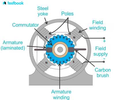
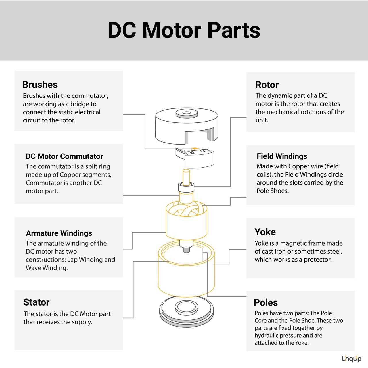
This section presents a breakdown of the essential elements that work together to create rotational movement through electrical energy. These elements interact in a precise manner, transforming electric input into continuous mechanical output.
Core Structural Elements
The central components include stationary and rotating elements. The fixed portion contains materials responsible for producing a magnetic field, while the moving part ensures continuous interaction with that field, driving rotation. These elements must be perfectly aligned for efficient operation.
Connection and Control Mechanisms
Wiring and control systems ensure the conversion of energy is stable and efficient. Electrical pathways allow current to pass through the moving elements, while control devices regulate speed and direction. Proper insulation and connections are critical to prevent energy loss and overheating.
| Component | Function | ||||||||
|---|---|---|---|---|---|---|---|---|---|
| Fixed Element | Produces and maintains the magnetic field | ||||||||
| Rotating Element | Interacts with the magnetic field to
How DC Motors Generate Motion
At the core of the movement process lies the conversion of electrical energy into mechanical force. This transformation allows devices to perform tasks by creating rotational or linear movement through controlled interactions between various components. The Role of Magnetic FieldsMagnetic fields play a crucial role in generating motion. When electricity flows through the internal setup, it creates a magnetic force that interacts with the stationary magnetic environment. The changing fields cause specific elements inside to rotate or shift. Electrical Flow and Movement ControlElectrical current direction influences the generated motion. Adjusting the current affects the speed and direction, offering precise control over the mechanical actions. Systems using these Inside the Armature and Windings
The intricate elements at the core ensure the system functions smoothly by transforming energy into mechanical action. These components are carefully crafted to maintain efficiency, stability, and durability across a range of operations. The Role of the Armature
The armature is a rotating element that interacts dynamically within the magnetic field. Its primary purpose is to carry currents that respond to magnetic forces, driving rotation effectively. The structural integrity of this part must remain uncompromised to support long-term performance The Role of Brushes in Operation
Brushes play a crucial role in ensuring smooth interaction between moving and stationary components. They act as a conduit, enabling the transfer of energy throughout the system. Without these essential elements, performance would be inconsistent, leading to interruptions during functioning.
Commutator Function in DC Motors
The commutator serves a pivotal role in converting alternating current into direct current within rotating devices. This component is essential for ensuring a consistent flow of electricity to the winding, facilitating continuous rotation in the system. By effectively reversing the direction of current at appropriate intervals, the commutator enables the establishment of a unidirectional current flow, which is crucial for maintaining the rotational motion. In essence, the commutator functions by segmenting the electrical circuit, allowing each segment to connect to the power supply at the right moment. This process minimizes interruptions in the flow of current, promoting efficiency and stability in operation. The design of the commutator is instrumental in ensuring that the electrical energy is effectively transformed into mechanical energy, thereby driving the intended action. Furthermore, the commutator’s ability to maintain contact with the rotating winding is vital. It allows for the seamless transfer of energy, reducing wear and tear on components while enhancing the overall performance of the device. In conclusion, the commutator is not merely a passive element; it is a dynamic component that plays an integral role in the successful operation of these electrical systems. Magnets and Magnetic Field GenerationThe interaction of certain materials under specific conditions leads to the creation of invisible forces that can influence various objects. This phenomenon plays a crucial role in a wide array of applications, providing the foundation for movement and energy transformation. By understanding these principles, we can explore how such forces are harnessed in practical scenarios. The Role of MagnetsMagnets are substances that produce a magnetic field, attracting or repelling other magnetic materials. The primary types include permanent and temporary magnets, each exhibiting distinct characteristics. Permanent magnets maintain their magnetic properties without external influence, while temporary magnets exhibit magnetism only in the presence of an external magnetic field. Generating Magnetic FieldsMagnetic fields arise from the motion of charged particles, typically electrons. When electric current flows through a conductor, it generates a magnetic field around it. This relationship between electricity and magnetism forms the basis of numerous technologies, enabling advancements in fields ranging from transportation to communication. Understanding this connection is essential for innovations that rely on electromagnetic principles. Bearings and Shaft: Ensuring Smooth Rotation
The interaction between essential components plays a crucial role in the efficient functioning of various devices. Among these components, the rotational element and its supportive structures are vital for achieving a seamless operation. Their design and materials significantly impact overall performance, minimizing friction and wear while maximizing longevity. Importance of Bearings
Bearings serve as pivotal elements that reduce friction between moving surfaces. By providing a smooth surface for rotation, they allow the shaft to turn effortlessly. This reduction in resistance not only enhances efficiency but also prolongs the lifespan of the assembly. Selecting the right type of bearing, whether it be ball, roller, or sleeve, can make a significant difference in performance. Role of the Shaft
The shaft acts as the central component that transfers motion from one area to another. Its design must ensure durability while facilitating rotation. Factors such as material choice and diameter are essential to prevent bending and deformation under load. A well-engineered shaft will contribute to stable operation, allowing for consistent performance across various applications. Wiring Connections for DC MotorsEstablishing proper connections is essential for the efficient functioning of these devices. Understanding the layout of the connections allows for effective power distribution and control. This section explores the necessary steps for creating reliable and functional wiring setups. Power Supply Connections: The first step involves connecting the power source to the terminals. Ensure that the positive terminal of the power supply links to the appropriate terminal of the device, while the negative terminal connects to the corresponding terminal. This configuration enables the flow of electricity, activating the component. Control Circuitry: Incorporating control systems is crucial for managing the operation. This may involve switches, relays, or controllers. When linking these elements, verify that the control signals correctly interface with the component to ensure seamless operation. Pay attention to the ratings and compatibility to prevent damage. Additional Considerations: Proper insulation and protection of connections enhance safety and performance. Utilize appropriate connectors and ensure that all wiring is secured to prevent accidental disconnections. Regular maintenance and inspection of the connections will promote longevity and reliability. Motor Housing and Its ImportanceThe enclosure that surrounds the internal components plays a crucial role in the functionality and longevity of any device. This structure not only provides support and protection but also influences the overall performance. Understanding its significance can enhance appreciation for the design and engineering behind these mechanisms. Functions of the Enclosure
Materials UsedControl Systems for Speed and Direction
Effective management of velocity and trajectory is crucial in various applications, ensuring precision and efficiency. Advanced systems allow for the fine-tuning of performance parameters, facilitating smooth operation and responsiveness to input commands. Types of Control SystemsKey Components |
