
Understanding the intricate configuration of vehicle assemblies is crucial for enthusiasts and technicians alike. Each element plays a significant role in ensuring optimal performance and reliability, making it essential to have a clear visual guide for easy reference.
Whether you’re performing maintenance or a complete overhaul, having a detailed view of how each segment interacts with others is indispensable. By focusing on the arrangement and alignment of these components, you’ll gain insights into the structure and functionality, simplifying any mechanical task at hand.
Accurate schematics and visual breakdowns help in identifying specific units quickly, allowing for efficient replacements or adjustments. With this comprehensive guide, you can delve deeper into the individual parts, ensuring seamless integration and smooth operation.
Understanding Key Components Overview
In this section, we delve into the core elements that make up the overall structure of the vehicle. By examining the various components, their placement, and functionality, we aim to provide a clear view of how these elements interconnect and contribute to the unit’s performance.
Exploring Mechanical Structures
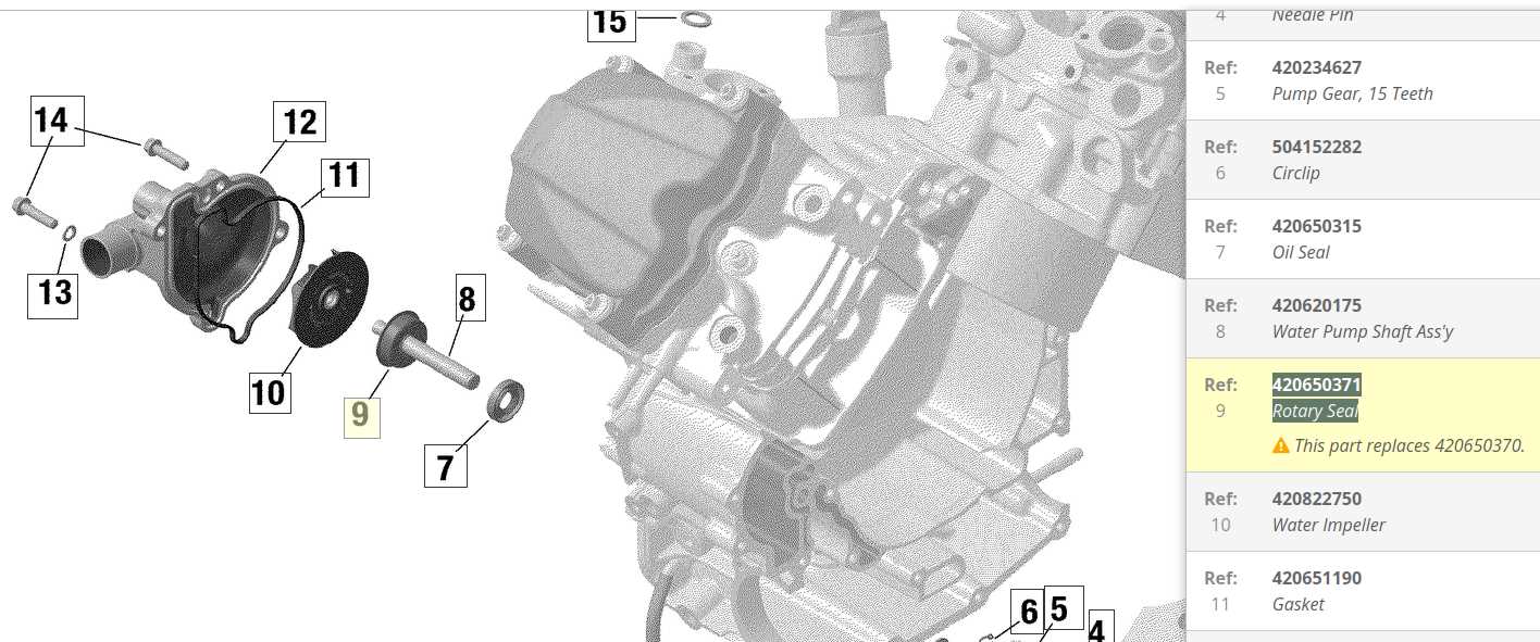
The mechanical framework serves as the foundation, supporting all other elements and ensuring stability during operation. Understanding how these structures interact is crucial for optimizing efficiency and identifying areas that may require maintenance or upgrades.
Electrical and Control Systems Analysis
The electrical circuits and control modules play a significant role in regulating the unit’s functions. Analyzing these systems helps in comprehending how they influence the overall performance and what steps can be taken to troubleshoot issues effectively. Focusing on the synergy between these systems is essential for maintaining seamless operation.
Engine Layout and Core Elements
The structural design of the motor and its fundamental components plays a crucial role in determining the machine’s overall performance and efficiency. Understanding how these elements are arranged and interact provides valuable insight into its operational dynamics.
Key Mechanical Components
The motor consists of various essential elements that work together seamlessly. Among these, the cylinder assembly forms the core, housing the piston movement responsible for generating power. Surrounding this setup are other crucial parts like the cooling system and the fuel injection mechanism, which ensure stability and effective performance under different conditions.
Optimized Design for Efficiency

A well-organized engine structure not only maximizes power output but also enhances fuel efficiency. By strategically positioning elements like the intake manifold and the exhaust system, the layout promotes optimal airflow and minimizes energy loss, contributing to a smoother and more responsive ride.
Identifying Suspension System Elements
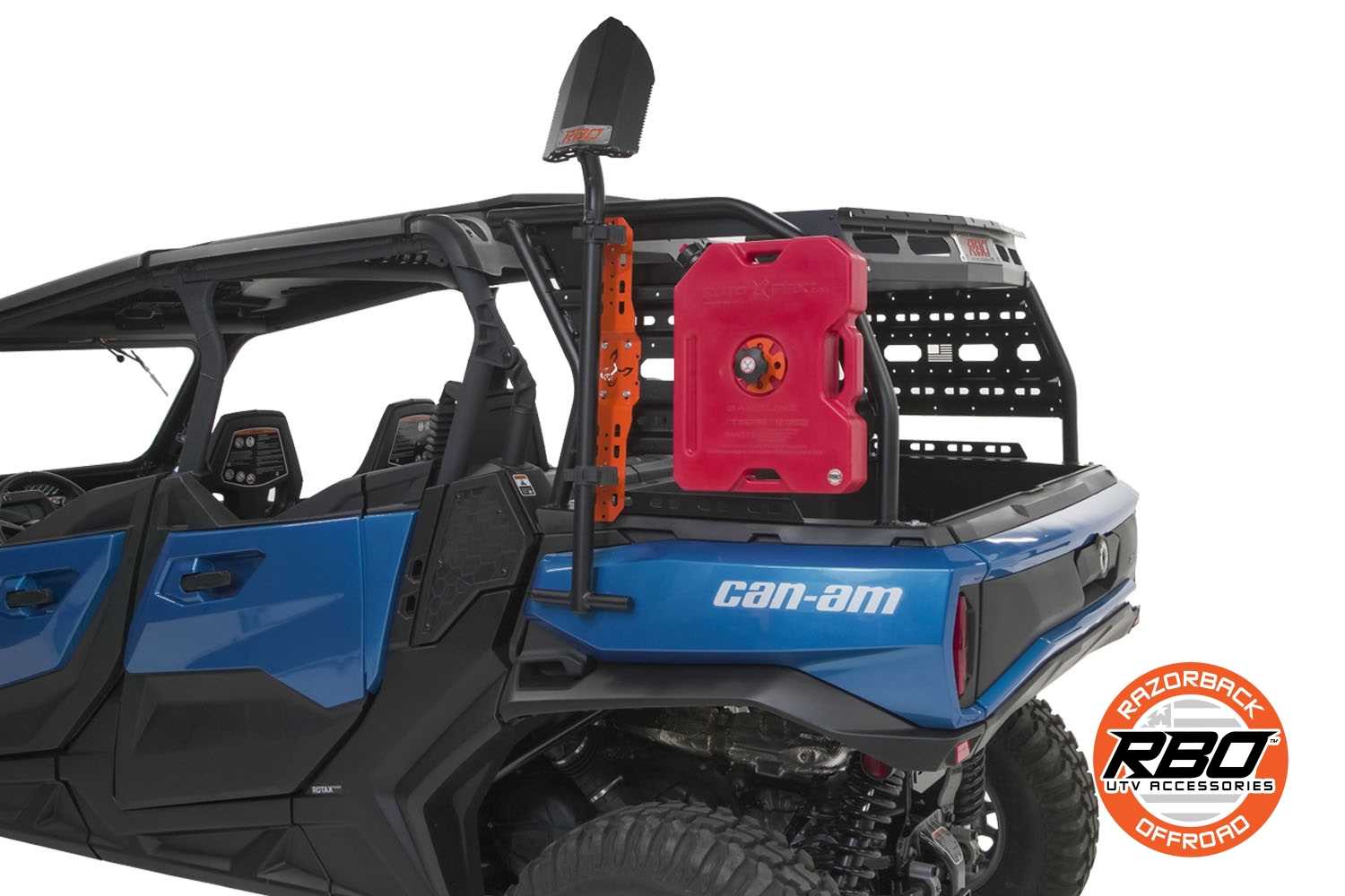
The suspension setup is crucial for ensuring a smooth ride and optimal handling on various terrains. Understanding each component’s role within this structure is key to maintaining performance and detecting issues early.
Key Components of the Suspension Structure
At the heart of this system are several integral elements that work in harmony to absorb shocks and provide stability. These components include springs, shock absorbers, and linkages that connect the wheels to the frame. Each part plays a distinct role, balancing flexibility and control during motion.
Recognizing Signs of Wear
It’s important to regularly inspect these elements for signs of wear or damage. Indicators such as unusual vibrations, uneven tire wear, or a bumpy ride can signal issues within the system. Prompt attention to these symptoms helps prevent further complications and ensures the longevity of the vehicle’s performance.
Shock Absorbers and Linkage Details
The performance and stability of any off-road vehicle largely depend on the quality and setup of its suspension system. Understanding the different components involved, especially the shock absorbers and their connections, is essential for ensuring smooth and controlled rides over challenging terrains.
Main Functions of the Suspension
The suspension’s primary role is to absorb impacts and maintain traction while navigating uneven surfaces. This involves distributing forces through various elements that work in harmony to deliver a balanced ride experience.
- Shock Absorbers: These components reduce the impact force, preventing sudden jolts and maintaining a consistent grip on the ground.
- Linkage Mechanism: A crucial part that connects the shock absorbers to the frame, facilitating motion control and energy dispersion.
Common Issues and Maintenance Tips
Regular inspection and maintenance of these parts are vital to prolong their lifespan and ensure peak performance. Identifying early signs of wear or damage can help in taking timely corrective actions.
- Check for oil leaks around the shock absorbers that might indicate internal damage.
- Inspect the linkage for any signs of corrosion or wear that could affect movement.
- Ensure all connections are securely fastened to prevent instability during rides.
Exploring Brake System Configuration
The brake system’s setup plays a crucial role in ensuring the safe operation of off-road vehicles. Understanding its components and how they interact is vital for anyone looking to maintain or enhance their vehicle’s performance. This section will delve into the fundamental elements and their arrangement within the system, providing clarity on how each part contributes to effective braking.
Key Components of the Setup
- Master Cylinder: Acts as the heart of the braking mechanism, transferring the force from the brake pedal to the hydraulic system.
- Brake Calipers: These units apply pressure to the brake pads, creating the friction necessary to slow down or stop the vehicle.
- Brake Pads and Rotors: The interaction between these two elements is critical for converting kinetic energy into heat, which effectively reduces speed.
Hydraulic System Dynamics

The hydraulic system within this configuration is designed to amplify the force applied by the driver, ensuring a responsive braking experience. This amplification is achieved through the use of brake fluid, which transmits the pressure evenly across all components.
- Fluid Reservoir: Supplies the necessary brake fluid to the master cylinder, maintaining consistent pressure throughout the system.
- Brake Lines: These tubes channel the hydraulic fluid to the calipers, ensuring that pressure is distributed evenly to all braking points.
By understanding the arrangement and function of these components, users can better diagnose issues or make informed decisions regarding upgrades or maintenance to optimize their braking performance.
Hydraulic Lines and Disc Placement
The efficient operation of a utility vehicle heavily relies on the proper configuration of fluid channels and braking components. Understanding the layout and arrangement of hydraulic systems is crucial for ensuring optimal performance and safety.
Hydraulic lines play a vital role in transferring fluid to various components, enabling effective operation. Here are some key considerations for their placement:
- Ensure lines are routed away from heat sources to prevent fluid degradation.
- Avoid sharp bends and kinks that could restrict flow or damage the line.
- Secure all connections to minimize the risk of leaks and ensure reliable performance.
Disc placement is equally important, as it affects the overall braking efficiency. Proper installation ensures effective contact with the pads and consistent stopping power. Consider the following:
- Align discs accurately with the caliper to avoid uneven wear.
- Check the thickness of the discs regularly to ensure they meet safety standards.
- Regularly inspect components for wear and replace as necessary to maintain functionality.
By adhering to these guidelines for hydraulic lines and disc placement, operators can enhance the reliability and safety of their vehicles, ensuring a smoother and more efficient driving experience.
Inspecting Electrical Wiring Setup
Evaluating the electrical configuration is crucial for ensuring the functionality and safety of any vehicle. A thorough examination of the wiring layout helps identify potential issues that could lead to malfunction or hazardous situations. Understanding how various components are interconnected can significantly enhance performance and reliability.
Initial Visual Inspection
Begin with a visual assessment of the wiring. Look for signs of wear, corrosion, or damage. Check for loose connections and frayed wires that may disrupt the flow of electricity. Ensuring all components are securely connected is vital for optimal operation.
Testing Connections and Continuity

Utilize a multimeter to test the integrity of electrical connections. Verify that current flows properly through each wire and connection point. Address any inconsistencies to prevent electrical failures that could compromise the overall system.
Battery Connections and Fuse Location
Understanding the wiring and electrical components of your vehicle is crucial for optimal performance. This section will outline the connection points for the power source and the placement of protective elements within the electrical system. Proper knowledge of these components ensures effective troubleshooting and maintenance, preventing potential electrical issues.
Power Source Connections
The main energy source is typically linked to the system through specific terminals. Ensure that the connections are secure and free of corrosion to guarantee a consistent flow of electricity. It is advisable to check the polarity before attaching cables; the positive terminal is usually marked with a “+” sign, while the negative is denoted with a “−”.
Fuse Accessibility and Protection
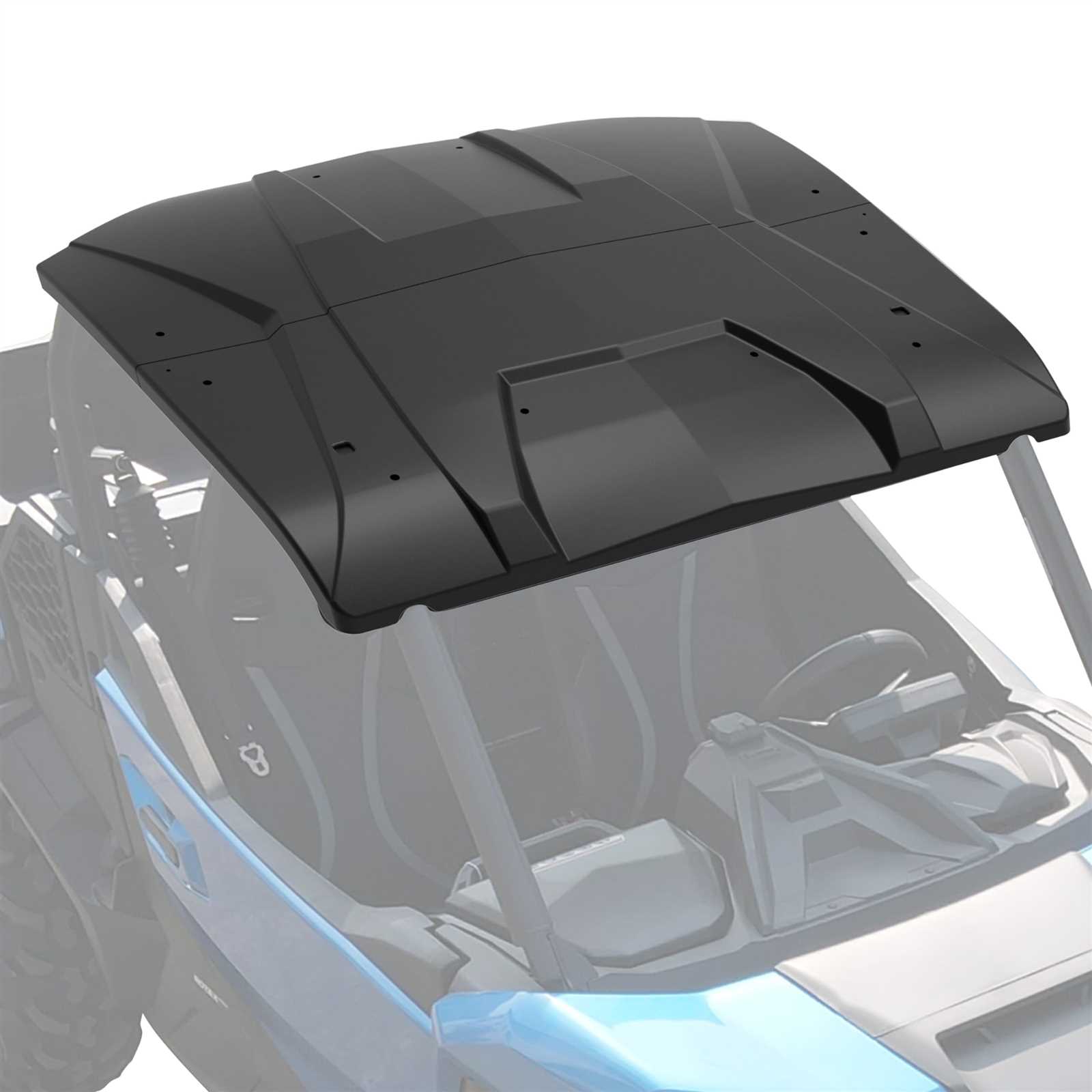
Fuses are vital for safeguarding the electrical circuits from overload. These protective devices can be found within a designated fuse box, typically located near the battery or under the dashboard. Regularly inspecting fuses for signs of damage or burnout is essential, as this can help maintain the integrity of the electrical system and prevent potential failures.
Examining Cooling Mechanism Structure

The efficiency of any vehicle’s performance largely depends on its ability to manage heat. An effective cooling system is vital for maintaining optimal operating temperatures, preventing overheating, and ensuring longevity. Understanding the various components involved in this mechanism can provide insights into its functionality and importance.
Key Components of the Cooling System
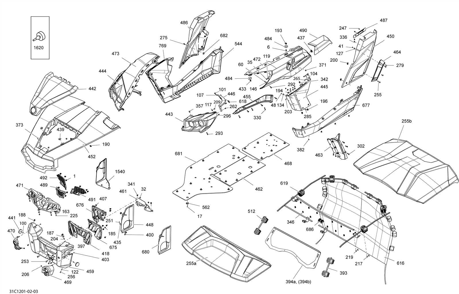
- Radiator: Acts as the primary heat exchanger, dissipating heat from the coolant into the air.
- Water Pump: Circulates coolant throughout the engine and cooling system, maintaining flow.
- Thermostat: Regulates coolant flow based on temperature, ensuring the engine reaches optimal heat levels.
- Coolant Reservoir: Stores excess coolant and allows for expansion and contraction during temperature changes.
- Cooling Fans: Assist in air circulation, especially when the vehicle is stationary or moving slowly.
Importance of Regular Maintenance
- Check coolant levels frequently to prevent air pockets and overheating.
- Inspect hoses and connections for wear and tear to avoid leaks.
- Clean the radiator fins to ensure maximum airflow and efficiency.
- Replace the thermostat and water pump as recommended to maintain system integrity.
- Monitor for signs of corrosion or scale build-up in the cooling system.
Radiator Assembly and Hose Routing
The cooling system is a crucial component of any vehicle, ensuring optimal temperature management for the engine and related systems. Proper configuration and arrangement of the cooling elements, including the radiator and associated hoses, play a vital role in maintaining efficient operation and preventing overheating.
The assembly of the cooling unit typically involves several interconnected components designed to facilitate the flow of coolant. The radiator serves as the primary heat exchanger, allowing heat to dissipate into the surrounding air. Hoses transport the coolant to and from the engine, ensuring a continuous cycle of heat absorption and release.
Accurate routing of the hoses is essential for achieving maximum efficiency. Each hose must be positioned to avoid kinks and obstructions, allowing for seamless coolant flow. Regular inspection of these components is recommended to detect wear or damage, which could compromise the overall effectiveness of the cooling system.
Transmission Arrangement Breakdown
This section delves into the intricate layout of the transmission system found in certain all-terrain vehicles. Understanding how the components interact is crucial for effective maintenance and troubleshooting. The transmission arrangement plays a vital role in the overall performance and efficiency of the vehicle, impacting power delivery and control.
Key Components and Their Functions
The primary elements of the transmission assembly include the gearbox, clutch, and drive shafts. Each component serves a specific purpose in ensuring smooth operation. The gearbox facilitates gear changes, allowing for optimal torque and speed adjustments. Meanwhile, the clutch connects and disconnects the engine power from the transmission, enabling gear shifts without stalling.
Maintenance Considerations
Regular inspection and maintenance of the transmission system are essential for prolonging vehicle life. Lubrication of moving parts is critical to prevent wear and ensure smooth operation. Additionally, checking for leaks and addressing any signs of malfunction promptly can avert costly repairs and enhance performance. Understanding the arrangement of these components is key to maintaining efficiency.
Gearbox Placement and Drive Shafts
The arrangement of the transmission system and the associated drive components is crucial for optimal vehicle performance. Proper positioning of these elements ensures efficient power transfer and enhances the overall driving experience. The configuration also affects the vehicle’s handling and stability, making it essential to understand the layout of these systems.
In this context, the gearbox serves as the heart of the drivetrain, converting engine power into usable torque. The drive shafts, extending from the gearbox, are responsible for delivering this torque to the wheels. Their alignment and placement significantly influence the vehicle’s capabilities in various terrains.
| Component | Function | Placement |
|---|---|---|
| Transmission | Converts engine power to torque | Located centrally, near the engine |
| Drive Shaft | Transfers torque to wheels | Extends from the transmission to the wheel hubs |
| Coupling | Connects drive shafts to the wheels | Positioned at the ends of the drive shafts |
Detailed Frame and Chassis Analysis
This section provides a comprehensive examination of the structural elements that form the foundation of an off-road vehicle. Understanding the composition and design of these components is crucial for enhancing performance, stability, and durability. The frame and chassis play pivotal roles in the overall functionality, influencing handling characteristics and the ability to withstand various terrains.
Structural Integrity and Material Composition
The foundation of any robust vehicle relies on the materials used in its construction. A careful selection of high-strength metals and composites ensures that the structure can endure rigorous conditions. The interplay between rigidity and flexibility in the design optimizes the vehicle’s response during operation, contributing to enhanced rider safety and comfort.
Impact on Handling and Performance
The design of the frame directly affects handling capabilities. A well-engineered chassis provides superior weight distribution, allowing for improved traction and maneuverability. Additionally, the integration of advanced engineering techniques aids in minimizing vibrations and enhancing stability, ultimately leading to a more enjoyable driving experience. Understanding these dynamics is essential for anyone looking to optimize their vehicle’s performance.